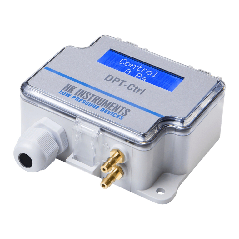
HK Instruments DPT-Ctrl-MOD Series User manual

Copyright HK Instruments 2022 www.hkinstruments. Installaonversion8.02022
INSTALLATION
INSTRUCTIONS
Pressure and flow controllers
DPT-Ctrl-MOD Series
• READ THESE INSTRUCTIONS CAREFULLY BEFORE ATTEMPTING TO
INSTALL, OPERATE OR SERVICE THIS DEVICE.
• Failuretoobservesafetyinformaonandcomplywithinstruconscan
result in PERSONAL INJURY, DEATH AND/OR PROPERTY DAMAGE.
• Toavoidelectricalshockordamagetoequipment,disconnectpower
beforeinstallingorservicinganduseonlywiringwithinsulaonratedfor
fulldeviceoperangvoltage.
• Toavoidpotenalreand/orexplosiondonotuseinpotenally
ammableorexplosiveatmospheres.
• Retaintheseinstruconsforfuturereference.
• Thisproduct,wheninstalled,willbepartofanengineeredsystemwhose
specicaonsandperformancecharacteriscsarenotdesignedor
controlledbyHKInstruments.Reviewapplicaonsandnaonalandlocal
codestoassurethattheinstallaonwillbefunconalandsafe.Useonly
experiencedandknowledgeabletechnicianstoinstallthisdevice.
Thankyouforchoosing an HK InstrumentsDPT-Ctrl-MOD series air han-
dling controller with dierenal pressure or airow transmier. The DPT-
Ctrl-MODseriesPIDcontrollersareengineeredforbuildingautomaonin
theHVAC/Rindustry.With thebuilt-incontrollerofthe DPT-Ctrl-MOD it
ispossibletocontroltheconstantpressureorowoffans,VAVsystemsor
dampers.Whencontrollingairow,itispossibletoselectafanmanufacturer
oracommonmeasuringprobethathasaK-value.
TheDPT-Ctrl-MODincludesanInputterminalthatenables the reading of
mulple signals such as temperature or control relays over Modbus. The
Input terminalhas oneinputchanneldesignedto accept 0−10V,NTC10k,
Pt1000,Ni1000/(-LG),andBININ(potenalfreecontact)signals.
DPT-Ctrl-MODseriesdevicesarecommonlyusedinHVAC/R
systems for:
•Controllingdierenalpressureorairowinairhandlingsystems
•VAVapplicaons
•Controllingparkinggarageexhaustfans
SPECIFICATIONS
Performance
Accuracy (from applied pressure):
Model2500:
Pressure<125Pa=1%+±2Pa
Pressure>125Pa=1%+±1Pa
Model7000:
Pressure<125Pa=1.5%+±2Pa
Pressure>125Pa=1.5%+±1Pa
(Accuracyspecicaonsinclude:generalaccuracy,
linearity,hysteresis,longterm
stability,andrepeonerror)
Overpressure:
Proofpressure:25kPa
Burstpressure:30kPa
Zero point calibraon:
ManualpushbuonorModbus
Response me:
1.0−20s,selectableviamenuorModbus
Communicaon
Protocol:MODBUSoverSerialLine
TransmissionMode:RTU
Interface:RS485
Byteformat(11bits)inRTUmode:
Codingsystem:8-bitbinary
Bitsperbyte:
1startbit
8databits,leastsignicantbitsent
rst
1bitforparity
1stopbit
Baudrate:selectableinconguraon
Modbusaddress:1–247addressesselectablein
conguraonmenu
Technical Specicaons
Media compability:
Dryairornon-aggressivegases
Controller parameter (selectable via menu and
Modbus):
Setpoint0...2500(model2500)
0...7000(model7000)
P-band 0...10000
I-gain 0...1000
D-factor0...1000
Pressure units (selectable via menu):
Pa,kPa,mbar,inWC,mmWC,psi
Flow units (selectable via menu):
Volume: m3/s, m3/hr,cfm,l/s
Velocity:m/s,/min
Measuring element:
MEMS,noow-through
Environment:
Operangtemperature:-20...50°C
Temperaturecompensatedrange0...50°C
Storagetemperature:-40...70°C
Humidity:0to95%rH,noncondensing
Physical
Dimensions:
Case:102.0x71.5x36.0mm
Weight:
150g
Mounng:
2each4.3mmscrewholes,onesloed
Materials:
Case: ABS
Lid:PC
Pressure inlets: Brass
Protecon standard:
IP54
Display
2-linedisplay(12characters/line)
Line1:Direconofcontroloutput
Line2:Pressureorairowmeasurement,
selectableviamenu
Ifinputisselected,line2showsalso
inputinformaon(forexample
temperature)
Size:46.0x14.5mm
Electrical connecons:
4+4posionspring-loadedterminals
Wire:0.2–1.5mm2(16–24AWG)
Cable entry:
Strainrelief:M16
Knockout:16mm
Pressure ngs
5.2mmbarbedbrass
+Highpressure
−Lowpressure
Electrical
Supply voltage:
24VACorVDC,±10%
Power consumpon:
<1.0W
Output signal:
viaModbus
Control output:
0-10V
Input signal:
0−10V,NTC10k,Pt1000,Ni1000/(-LG)orBININ
Conformance
Meetstherequirementsfor:
CE: UKCA:
EMC: 2014/30/EU S.I.2016/1091
RoHS: 2011/65/EU S.I.2012/3032
WEEE: 2012/19/EU S.I.2013/3113
INTRODUCTION WARNING
APPLICATIONS
RoHS
COMPLIANT

Copyright HK Instruments 2022 www.hkinstruments. Installaonversion8.02022
SCHEMATICS
INSTALLATION
STEP 1: MOUNTING THE DEVICE
1)Mountthedeviceinthedesiredlocaon(seestep1).
2)Openthelidandroutethecablethroughthestrainreliefandconnectthe
wirestotheterminalblock(s)(seestep2).
3)Thedeviceisnowreadyforconguraon.
WARNING!Applypoweronlyaerthedeviceisproperlywired.
1)Selectthemounnglocaon(duct,wall,panel).
2)Usethedeviceasatemplateandmarkthescrewholes.
3)Mountwithappropriatescrews.
Display connecon
A
B
24 V
GND
LEDs
Joysck1
Joysck2
Joysck3
Select
Up
Down
Menu buons
Terminal
blocks
Pressure
sensor
Input terminal
configuraon
jumpers
Control out
Input
GND
GND
Figure 1a - Mounng orientaon
YES NO NO
STEP 3: CONFIGURATION
2)Zeropointadjustment.Formoreinformaon,seeStep4.
PRESS. UNIT
Pa
SELECT
UP
DOWN
SELECT
ZERO SENSORS
SELECT
UP
DOWN
3)Selectthefunconingmodeofthecontroller:PRESSUREorFLOW.
-SelectPRESSUREwhencontrollingdierenalpressure.
Gotopoint3.1.
-SelectFLOWwhencontrollingairow.
Gotopoint3.2.0.
CONTROL UNIT
PRESSURE
SELECT
UP
DOWN
When control unit PRESSURE is selected.
3.1)Selectpressureunitfordisplayandoutput:Pa,kPa,mbar,inWCormmWC.
Thengotopoint4.
When control unit FLOW is selected.
3.2.0)Selectthefunconingmodeofthecontroller
-SelectManufacturerwhenconnecngDPT-Ctrl-MODtoafanwithpressure
measurementtaps.
-SelectCommon probewhenusingDPT-Ctrl-MODwithacommonmeasurement
probethatfollowstheformula:
q=k∙√∆P(i.e.FloXact)
MANUFACTURER
Common probe
SELECT
UP
DOWN
Common probe Flakt Woods
SELECT
UP
DOWN
STEP 2: WIRING DIAGRAMS
ForCEcompliance,aproperlygroundedshieldingcableisrequired.
1)Unscrewthestrainreliefandroutethecable(s).
2)Connectthewiresasshowningure2aand2b.
3)Tightenthestrainrelief.
Figure 2a - Wiring diagram
A
B
24 V
GND
+Power Supply
24VDC / 24VAC
Control out
Input
GND
GND
Modbus
Figure 2b - Wiring diagram example for input signals
Input
GND
ntc10k J1
J2
J3
IN
Input ntc10k temperature:
Funcon04-Readinputregister3x0007
3.2.1)If
Commonprobe
selected:selectmeasurementunitsusedintheformula
(akaFormulaunit)(i.e.l/s)
b. If
Commonprobe
selectedinstep3.2.0:
EachcommonprobehasaspecicK-value.SelecttheK-valuefromcommonprobe
manufacturer’sspecicaons.
AvailableK-valuerange:0.001...9999.000
FORMULA UNIT
l/s
SELECT
UP
DOWN
3.2.2)SelectK-value
a.Ifmanufacturerselectedinstep3.2.0:
EachfanhasaspecicK-value.SelecttheK-valuefromfanmanufacturer’sspeci-
caons.
K-VALUE
9000.000
SELECT
UP
DOWN
3.2.3)Selectowunitfordisplayandoutput:
Flowvolume:m3/s, m3/h,cfm,l/s
Velocity:m/s,f/min
FLOW UNIT
m3/s
SELECT
UP
DOWN
1)Presstheselectbuonfortwosecondstoopenthedevicemenu.
4)SelecttheaddressforModbus:1...247
ADDRESS
99
SELECT
UP
DOWN
ItisrecommendedtouseshieldedtwistedpaircableforModbuscabling.
Thecableshieldmustbeearthedonlyinonepoint,normally,attheendof
themaincable.

Copyright HK Instruments 2022 www.hkinstruments. Installaonversion8.02022
7)Selecttheresponseme:1...20s.
RESPONSETIME
4 s
SELECT
UP
DOWN
BAUD RATE
9600
SELECT
UP
DOWN
PARITY BIT
NONE
SELECT
UP
DOWN
5)Selectthebaudrate:9600/19200/38400.
6)Selecttheparitybit:None/Even/Odd
9)Selecttheinputtype.
Passivetemperaturesensors:PT1000/Ni1000/Ni1000LG/NTC10k
Voltageinput:VINPUT
Switchinput:BININ
Noinput:NONE
INPUT
PT1000
SELECT
UP
DOWN
10)Selectthesetpointofthecontroller(SP2isonlyavailablewithBININswitch
informaon):
CONFIGURATION CONTINUED
NOTE! Always zero the device before use.
Supplyvoltagemustbeconnectedonehourbeforethezeropointadjust-
mentiscarriedout.AccessviaModbusorbypushbuon.
1)Loosebothtubesfromthepressureinlets+and-.
2)Acvatethedevicemenubypushingthetheselectbuonfor2
seconds.
3)SelectZero sensorbypressingtheselectbuon.
4)WaitunltheLEDturnsoandtheninstalltubesagainforthe
pressureinlets.
STEP 4: ZERO POINT ADJUSTMENT
SELECT
STEP 5: INPUT SIGNAL CONFIGURATION
InputsignalscanbereadoverModbusviaDPT-MODRS485interface.
Signals Accuracy for measurement Resoluon
0...10V <0,5% 0,1%
NTC10k <0,5% 0,1%
Pt1000 <0,5% 0,1%
Ni1000/(-LG) <0,5% 0,1%
BININ(potenalfreecontact)
Thejumpersshould be set accordingtothe instruconsbelowandthe value
shouldbereadfromtherightregister.
Figure 3 - Input signal conguraon
J1
J2
J3
IN
J1
J1
J1
J2
J2
J2
J3
J3
J3
NTC10k / BIN IN
Pt1000 / Ni1000/(-LG)
0...10 V
D-VALUE
1.00
SELECT
UP
DOWN
15)Pushtheselectbuontoexitmenu.
SELECT
EXIT MENU SELECT
12)Selectproporonalbandaccordingtoyourapplicaon
specicaons.
P-VALUE
206
SELECT
UP
DOWN
13)Selectintegralgainaccordingtoyourapplicaonspecicaons.
I-VALUE
4.00
SELECT
UP
DOWN
14)Selectderivaonmeaccordingtoyourapplicaon
specicaons.
STEP 6: TEMPERATURE COMPENSATION
Thedeviceincludesanoutdoortemperaturecompensaonfunconthatcan
beenabledfromthemenu.Whenacvatedandanoutdoortemperaturesensor
isaached,theeecvesetpointofthedevicewillbemodiedtocompensate
forthecoldoutdoorair.Thismayresultinenergysavings.
If temperaturecompensaonis enabled, thedevicewill linearly decreasethe
user’s setpoint (REF FLOW/REF PRESSURE) by 0 % to TC DROP % from TC
START TE to TC STOP TE.
Thedeviceenforcesa+5°Cdierence betweenthe startand stoptempera-
tures.Thestarttemperaturemustbehigherthanthestoptemperature.
1)Connectandcongureanoutdoorairtemperaturesensor.Seestep5.
2)Enabletemperaturecompensaon.
4)Setthestoppingtemperatureforcompensaon.
TC STOP TE
-15 °C
SELECT
UP
DOWN
TEMP COMP
ON
SELECT
UP
DOWN
TC START TE
5 °C
SELECT
UP
DOWN
3)Setthestarngtemperatureforcompensaon.
5)Setthemaximumdroppercentageforcompensaon.
TC DROP %
25.0
SELECT
UP
DOWN
8)SelecttheFixedOutput(OFF/0...100%),(seestep7FixedOutput).
10.1)IftheCONTROLUNITisselectedPRESSURE.
SELECT
UP
DOWN
REF PRES SP1
10 Pa
REF PRES SP2
100 Pa
10.2)IftheCONTROLUNITisselectedFLOW.
SELECT
UP
DOWN
REF FLOW SP1
25.000 m3/s
REF FLOW SP2
35.000 m3/s
11)SelecttheTEMPCOMP(OFF/ON),(seestep6,TemperatureCompensaon).

Copyright HK Instruments 2022 www.hkinstruments. Installaonversion8.02022
Thesellerisobligatedtoprovideawarrantyofveyearsforthedeliveredgoods
regarding material and manufacturing. The warranty period is considered to
startonthedeliverydateoftheproduct.Ifadefectinrawmaterialsorapro-
ducon aw isfound, theseller isobligated,whentheproduct issent tothe
sellerwithoutdelayorbeforeexpiraonofthewarranty,toamendthemistake
athis/herdiscreoneitherbyrepairingthedefecveproductorbydelivering
freeofchargetothebuyeranewawlessproductandsendingittothebuyer.
Deliverycostsfortherepairunderwarrantywillbepaidbythebuyerandthe
returncostsbytheseller.Thewarrantydoesnotcomprisedamagescausedby
accident,lightning,oodorothernaturalphenomenon,normalwearandtear,
improperorcarelesshandling,abnormaluse,overloading,improperstorage,in-
correctcareorreconstrucon,orchangesandinstallaonworknotdonebythe
seller.Theseleconofmaterialsfor devicespronetocorrosionis the buyer’s
responsibility,unlessotherwiseislegallyagreedupon.Shouldthemanufacturer
alterthestructureofthedevice,thesellerisnotobligatedtomakecomparable
changestodevicesalreadypurchased.Appealingforwarrantyrequiresthatthe
buyerhascorrectlyfullledhis/herduesarisenfromthedeliveryandstated
inthe contract.Thesellerwillgivea new warranty for goodsthathave been
replacedorrepairedwithinthewarranty,howeveronlytotheexpiraonofthe
originalproduct’swarrantyme.Thewarrantyincludestherepairofadefec-
ve partordevice, orifneeded, a newpartordevice, but not installaon or
exchangecosts.Undernocircumstanceisthesellerliablefordamagescompen-
saonforindirectdamage.
Register Parameter descripon Data Type Value Range
4x0001 Manufacturer 16bit 0...8
0=FläktWoods
1=Rosenberg,
2=Nicotra-Gebhardt
3=Comefri
4=Ziehl-Abegg
5=ebm-papst
6=Gebhardt
7=Nicotra
8=Commonprobe
4x0002 Formulaunit(ifmanufacturer
selecon=commonprobe) 16bit 0...5 0=m3/s,1=m3/h,2=cfm,
3=l/s,4=m/s,5=f/min
4x0003 K-factorintegral 16bit 0...9999 0...9999
4x0004 K-factordecimal 16bit 0...999 0...999
4x0005 Responseme 16bit 0...20 0...20s
4x0006 PIDcontrolunit 16bit 0...1 0=Pressure,1=Flow
4x0007 PIDpressureref 16bit -250...2500(model2500)
-700...7000(model7000)
-250...2500(model2500)
-700...7000(model7000)
4x0008 PIDowrefinteger 16bit 0...30000 0...30000
4x0009 PIDowrefdecimal 16bit 0...999 0...999
4x0010 PIDpvalue 16bit 0...10000 0...10000
4x0011 PIDiinteger 16bit 0...1000 0...1000
4x0012 PIDidecimal 16bit 0...99 0...99
4x0013 PIDdinteger 16bit 0...1000 0...1000
4x0014 PIDddecimal 16bit 0...99 0...99
4x0015 Overdrivevalue 16bit 0...100 0...100%
4x0016 Overdriveacve 16bit 0...1 0=O,1=On
4x0017 Temperaturecompensaon 16bit 0…1 0=O,1=On
4x0018 Temp.comp.startTE 16bit -45…50 -45…50°C
4x0019 Temp.comp.stopTE 16bit -50…45 -50…45°C
4x0020 Temp.comp.dropintegerpart 16bit 0…99 0…99%
4x0021 Temp.comp.dropdecimalpart 16bit 0…999 0.0…0.999%
4x0022 PIDPressureRefSP1 16bit -250...2500(model2500)
-700...7000(model7000)
-250...2500(model2500)
-700...7000(model7000)
4x0023 PIDPressureRefSP2 16bit -250...2500(model2500)
-700...7000(model7000)
-250...2500(model2500)
-700...7000(model7000)
4x0024 PIDFlowRefSP1integer 16bit 0...30000 0...30000
4x0025 PIDFlowRefSP1decimal 16bit 0...999 0...999
4x0026 PIDFlowRefSP2integer 16bit 0...30000 0...30000
4x0027 PIDFlowRefSP2decimal 16bit 0...999 0...999
4x0028 Flowunit(displayandPIDSP) 16bit 0...5 0=m3/s,1=m3/h,2=cfm,
3=l/s,4=m/s,5=f/min
Funconcode03-Readholdingregister,Funconcode06-Writesingleregister,
Funconcode16-Writemulpleregisters
Funconcode05-Writesinglecoil
Register Parameter descripon Dat a Type Value Range
0x0001 Zeroingfuncon Bit0 0...1 0=O,1=On
Thepartsleoverfrominstallaonshouldberecycled
accordingtoyourlocalinstrucons.Decommissioned
devicesshouldbetakentoarecyclingsitethatspecial-
izesinelectronicwaste.
STEP 9: MODBUS REGISTERS
RECYCLING/DISPOSAL
WARRANTY POLICY
Funconcode02-Readinputstatus
Register Parameter descripon Dat a Type Value Range
1x0001 Input:BININ Bit0 0...1 0=O,1=On
MODBUS REGISTERS CONTINUED
STEP 7: Fixed output
Fixedoutputsengscanbeenabledtosetthecontroloutputtoapresetvalue.Pri-
marypurposeofthisfunconalityistoenabletheadjustmentofairvalvesandter-
minalswithouttheDPT-Ctrlaecngtheductpressureorairow.Itcanalsoaidin
troubleshoongtheinstallaon.
1)Toenablethexedoutput,scrolltoitsposioninthemenu.
2)Presstheselectbuonandselectthedesiredxedoutputvalue.Theoutputwill
nowstayatthisvalueindenitely.Innormaloperaonmode(shownbelow),the
upperrowofthedisplaywillshowFIXEDxx%toindicatetheoutputisxed.
FIXED OUTPUT
OFF
SELECT
UP
DOWN
FIXED 50 %
184 Pa
3)Toenablethenormalcontroloutputanddisablethexedoutput,scrolltoits
posion,selectitandsetvaluetoOFF.
Fixed output funcon is also available via Modbus. (4x0016: Overdrive acve,
4x0015:Overdrivevalue)
Funconcode04-Readinputregister
Register Parameter descripon Dat a Type Value Range
3x0001 Programversion 16bit 0...1000 100...9900
3x0002 PressurereadingA 16bit -250...2500(model2500)
-700...7000(model7000)
-250...2500(model2500)
-700...7000(model7000)
3x0003 Input0...10V 16bit 0...100 0...100%
3x0004 InputPT1000 16bit -500...500 -50...+50°C
3x0005 InputNi1000 16bit -500...500 -50...+50°C
3x0006 InputNi1000-LG 16bit -500...500 -50...+50°C
3x0007 InputNTC10k 16bit -500...500 -50...+50°C
3x0008 Flowm3/s 16bit 0...10000 0...100m3/s
3x0009 Flowm3/h 16bit 0...30000 0...30000m3/h
3x0010 Flowcfm 16bit 0...30000 0...30000cfm
3x0011 Flowl/s 16bit 0...3000 0...3000l/s
3x0012 Velocitym/s 16bit 0...1000 0...100m/s
3x0013 Velocityf/min 16bit 0...5000 0...5000f/min
STEP 8: Using the 2SP-feature
2SP(setpoint)isafeaturewithabinaryinputtoselectbetweentwouser-adjustable
setpoints.Thedesiredsetpointcanbeselected,forexample,withweeklyclock,turn
switchorkeycardswitch.
1)SelectINPUT=>BININ. INPUT
BIN IN
SELECT
UP
DOWN
J1
J2
J3
NTC10k / BIN IN
2)Setthejumpersasshownbeside
todeterminetheinputsignal.
This manual suits for next models
2
Other HK Instruments Controllers manuals
