HKA TR-707 User manual

TR-707 ROM Expansion
This kit includes:
1x Pre-assembled PCB
1x 10-way ribbon cable with IDC plug
1x 28-way turned-pin IC socket
You will need:
- Fine tipped soldering iron & lead solder
- De-soldering pump or braid
- Phillips head screwdriver
- Wire strippers
www.hkadesign.org.uk April 2022
Installation Instructions
hkadesign

Fitting this kit requires a good level of skill in both soldering and desoldering. Unless you
are absolutely sure of your abilities, have good quality tools and practice using them, I do
not recommend that you t it yourself.
The printed circuit boards in the TR-707 are not as robust as modern ones and cannot take much
abuse. Overheating solder joints can very easily cause tracks and pads to lift, requiring time-
consuming rework to put right.
If you are not comfortable performing the work yourself, I offer an installation service for customers
in the UK; otherwise a local synth repair technician should be able to to this work.
Also importantly - your TR-707 needs to be fully functional before installing the kit. This should go
without saying, but if your machine has voice issues, power issues, etc., the kit will not magically
x them for you.
Introduction
Thank you for purchasing the TR-707 ROM Expansion board.
It has now been updated to allow changing banks on-the-y while the machine is running. This is
done by holding down the ENTER key and pressing one of the rst 8 step keys, or can be still be
done by holding down one of these step keys while powering on the machine as before.
If you have a kit with a 9-way ribbon cable, you have the older version and you need the
older instructions. If you have a kit with a 10-way ribbon cable (April 2022 onwards), you
have the new version and this is the correct document for your kit.
The installation procedure for this new version is mostly the same as the old version, with just a
slight change to the ribbon cable connections on the panel board.
Finally, this manual refers to the TR-707 throughout, as it’s by far the more common machine, but
the expansion board works ne in the TR-727, and the installation process is identical.
Read me rst!
TR-707 ROM Expansion Page 2

Installation
Remove the batteries from their compartment.
Back up your patterns rst if you don’t want to lose them!
1.
Remove all of the slider caps (an IC puller works really well for this), putting them somewhere
safe, and remove the 7x screws on the underside of the case.
2.
With the machine face down on a soft surface, lift off the bottom cover. Desolder or clip the
wires going to the battery compartment, noting the positive and negative connections. Set
the bottom cover aside for now.
3.
Carefully disconnect the at ex ribbon going from the main board off to the cartridge
connector. To do so, pry the retaining clip away from the body of the connector, and the
ribbon will slide out. Temporarily remove the cartridge connector (2x screws) for better
access to the main board.
4.
Remove the screws that secure the main PCB assembly into the top case :
• 2x screws either side of the MIDI sockets on the back panel
• 2x screws in opposite corners of the circuit board assembly (top right and bottom left)
• 1x screw holding the ground wire to the panel board (2x screws + wires on early units)
5.
Lift the main PCB assembly out of the case, while disconnecting the two cables that join it
to the panel board. This is most easily done by holding the machine on end, with sockets
facing downwards, and the power button pressed in.
6.
With the main board assembly out of the case, locate IC34 and IC35 in the front right-hand
corner of the PCB (both marked HN61256P). Carefully de-solder and remove them, and
solder the included chip socket in place of IC35. The IC34 location is now unpopulated.
7.
40151
40174
IC32 IC33
40273
IC36
uPC624
IC37
HN61256
IC34
HN61256
IC35
Front right-hand corner of TR-707 main board
Fit included
IC socket here
at IC35
Remove IC34 + IC35
TR-707 ROM Expansion Page 3
Plug the expansion board into the socket, ensuring that the pins are lined up correctly.
You will probably need to adjust the two at cables going to the mixer board to make
room - the left-hand cable marked ‘F201’ can be folded down behind the rear edge of the
expansion board, and the right-hand cable marked ‘F202’ can overhang the top.
8.

Installation
TR-707 ROM Expansion Page 4
The rst 8 wires of the ribbon cable need to be fanned out to 3cm, stripped to 2mm and
tinned with solder.
Wires 9 & 10 should be separated from the rst 8, all the way back to the connector, and
cut to 20cm total length. As with the others, these should be fanned out to 3cm, stripped to
2mm and tinned.
9.
Cut to 20cm
Fan out to 3cm
Separate from wires 1-8
30cm
(as supplied)
12345678
910
Drawing not to scale!
Fan out to 3cm
Stripe

Installation
Solder the wires from the ribbon cable to locations on the panel board as shown below. Once
this is done, fold it as shown and secure the ribbon cable down with a piece of insulation
tape.
10.
TR-707 ROM Expansion Page 5
D311
D312
CN303
35 25
IC302
CN302
24 14
IC301
D350
D313
1357 2468
D315 D314
D310
D309
D324 D323 D322 D321
D352
D353
814
7
D316
IC303
(unlabelled on board)
9
10
Ribbon cable wire Connect to Signal
1 (with red stripe) CN302-14 Data bus bit 0
2 CN302-15 Data bus bit 1
3 CN302-16 Data bus bit 2
4 CN302-17 Data bus bit 3
5 CN302-18 Data bus bit 4
6 CN302-19 Data bus bit 5
7 CN302-20 Data bus bit 6
8 CN302-21 Data bus bit 7
9 IC303-1 Row select 1 (step keys 1-8)
10 IC303-13 Row select 3 (row with ENTER key)

TR-707 ROM Expansion Page 6
Installation
Reinstall the main PCB assembly in the top case, reconnecting the two cables that join it to
the panel board. Like the disassembly, this is easiest done with the machine on end. Plug
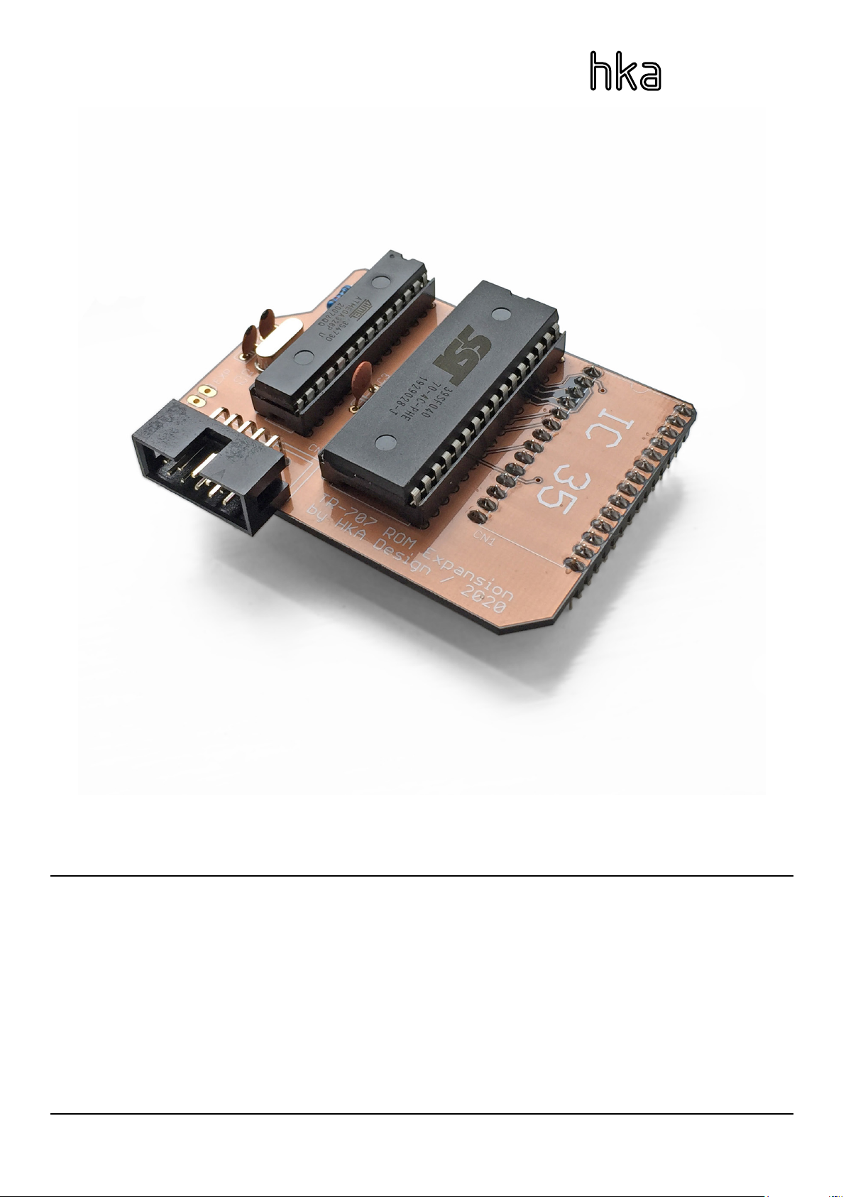
the ribbon cable into the expansion board.
Replace the screws that secure the PCB assembly in the top case, which you removed in
Step 5, also replacing the ground wire(s).
11.
Replace the cartridge connector and reconnect the at ex ribbon.
Re-solder the wires to the battery compartment.
12.
Replace the bottom cover, 7x case screws, and slider caps, and put the two AA cells
back in the battery compartment.
13.
When powering up the machine for the rst time after replacing the batteries, the
pattern memory will be scrambled and the machine may behave strangely until you
do a factory reset. To do so, power on the TR-707 while holding down the TRACK and
PATTERN GROUP A buttons.
14.
If the bank selection system appears to be functioning, but the sounds themselves are
playing back with digital distortion, or are scrambled, it is very likely that there is something
wrong with the connections between the expansion board and the IC35 socket. Check that
it is seated properly in the socket, and check for any solder bridges, dry joints, damaged
tracks or pads where you soldered the socket.
If the sounds are playing normally but the bank selection is not working as intended, check
the connections from the ribbon cable to the panel board. Check that the wires are tted in
the correct sequence and are connected to the right locations.
If the machine crashes at startup, you probably have a short between two or more of the
locations where wires 1-8 connect to the panel board, as these are the TR-707’s data bus.
Otherwise, check that no wires are getting pinched in the case or by screws, and also that
the various connectors inside the machine have been reconnected – especially the two that
join the top case and panel board to the main board, it happens to the best of us! :-)
Troubleshooting

The ROM Expansion has 8x sound banks, which are listed below.
The bank is selected either by holding down the ENTER button and pressing one of the rst
8 step keys; or by holding down one of the rst 8 step keys while powering on the machine.
The setting will be remembered and recalled at next power-on.
The ROM Expansion kit will replace all of the sounds, except for the last two: crash + ride
on the TR-707, quijada and star chime on the TR-727. These are stored on separate ROMs
and accessed with their own circuitry. A separate add-on board, which is in development,
would allow these to be switched with the rest of the sounds.
1 2 3 4 5 6 7 8
BASS DRUM SNARE DRUM LOW TOM MID TOM HI TOM RIMSHOT COWBELL
9
1 2 3 4 5 67 8 9
727707 808 909 Linn
Drum LM-1 DMX
707
+
727
Selecting banks
TR-707 ROM Expansion Page 7
Table of contents
Popular Computer Hardware manuals by other brands

RF Player
RF Player RFP1000 user guide

Fujitsu Siemens Computers
Fujitsu Siemens Computers PRIMERGY RX300 S4 operating manual

Silex technology
Silex technology SX-570 Developer’s Reference

Noctua
Noctua NH-U12DX i4 installation manual

Watercool
Watercool HEATKILLER GPU-X3 Core Series Assembly instructions

Allegro MicroSystems
Allegro MicroSystems A1569 user manual

Aquatic
Aquatic SCM-4800 quick start guide

Cisco
Cisco PRP-2= Installation and configuration guide

Connect Tech
Connect Tech NVIDIA Jetson TX2 user guide

ekwb
ekwb EK-FC980 GTX Ti Classy KPE Series INSTALLATION AND MOUNTING MANUAL

Joy-it
Joy-it RS232-SHIELD manual

Intel
Intel SRCZCRX - RAID Controller Storage Hardware user's guide