HKC APL-9 Series Instruction manual

APL-9 Series Limit Switch Box
Installation Operation & Maintenance Manual
Doc No. : HumG-APL9-21 Rev0 Page 1 / 10 Valve Automation Leader HKC
APL-9 Series Valve Position Monitor
All Stainless Steel Enclosure
Installation, Operation & Maintenance Manual
Address : 26, Emtibeui 28-ro, Siheung-si, Gyeonggi-do, 15119, Republic of Korea
Tel : +82-31-488-8266, Fax : +82-31-488-8269, Home page : www.hkcon.co.kr, email : hkcon@hkcon.co.kr

APL-9 Series Limit Switch Box
Installation Operation & Maintenance Manual
Doc No. : HumG-APL9-21 Rev0 Page 2 / 10 Valve Automation Leader HKC
Table of Contents
1 General ............................................................................................................................................................... 3
2 Special characteristics ................................................................................................................................ 3
3 Ordering Information ................................................................................................................................. 3
4 Standard and Optional Specification ................................................................................................. 4
5 Marking .............................................................................................................................................................. 4
6 Standard Features ........................................................................................................................................ 5
7 Installation ........................................................................................................................................................ 6
7.1 Mounting bracket ..............................................................................................................................6
7.2 Mounting limit switch box ...........................................................................................................6
7.3 Setting cam ...........................................................................................................................................6
7.4 Wiring .......................................................................................................................................................7
8 Maintenance .................................................................................................................................................... 8
9 Inspection .......................................................................................................................................................... 8
10 Storage ............................................................................................................................................................... 8
11 Trouble Shooting .......................................................................................................................................... 8
12 Tools .................................................................................................................................................................... 9
13 Installation and Maintenance Tips ...................................................................................................... 9
14 Dimensions ....................................................................................................................................................... 9

APL-9 Series Limit Switch Box
Installation Operation & Maintenance Manual
Doc No. : HumG-APL9-21 Rev0 Page 3 / 10 Valve Automation Leader HKC
1. General
1.1. HKC APL series limit switch box is designed to provide accurate and reliable valve position signaling and
indicating of most valves or actuators manufactured.
1.2. HKC has developed press-formed all stainless steel valve position monitor APL9 series. In recent years the
demand for stainless steel valve position monitor steadily increased for use in a variety of building and
manufacturing plants. This APL9 Series model has a full variety of superb features that include the
lightweight and compact design, cleanliness, high insulation and corrosion resistance, unique to stainless
steel.
1.3. APL limit switch box consists of a visual position indicator, quick-set cam ass’y, terminal strip, switch ass’y
and easy mounting bracket. Quick-set cam allows for a quick and simple hand operation in the setting of
switches.
2. Special characteristics
2.1. Made of press-formed stainless steel to secure long life.
Housing, cover, bracket are made of press-formed and welded stainless steel. (Standard: JIS G4304 SUS304,
Option: JIS G4304 SUS316, SUS316L) Therefore, it is surpassing corrosion resistivity and durability.
2.2. Excellent design and cleanness, light weight.
APL-9 Series is compact configuration and light weight. It is easy handle and install, about 2/3 of
aluminum limit switch box and about 1/5 of stainless limit switch boxes in weight.
2.3. High corrosion resistivity
Anticorrosive coating is not necessary
2.4. Visual Position Indicator
Indicator window was firmly fixed to the six hooks made of metal.(Patent Pending)
2.5. Quick-set cam
Spring loaded splined cam and special cam for proximity sensor
2.6. No need to adjust again initial setting.
Easy setting is available without tool.
2.7. Dual cable entries
Standard: Two NPT 1/2”, Option: Two M20, PG 13.5, PF 1/2”
2.8. Captive cover bolts
Do not worries to lose cover bolts while cover open.
2.9. Easy mounting bracket
NAMUR standard stainless steel shaft and bracket set.
3. Ordering Information
APL - 9 1 0 L S
① ② ③ ○
4
① Enclosure type
9 : Stainless steel, Weather proof [IP 67 (Standard)
Watertight IP68 2m 72 hrs (Option) ----- 17rev1]
② Switch type
Mechanical switch (Ambient temperature : -20°C to +60 °C)
10 : 2-SPDT (Wonwoo Starion: SZM-V16-5FA-61, or Zippy: VA2-16)
11 : 3-SPDT (Wonwoo Starion: SZM-V16-5FA-61, or Zippy: VA2-16)
12 : 4-SPDT (Wonwoo Starion: SZM-V16-5FA-61, or Zippy: VA2-16)
13 : 2-SPST (Wonwoo Starion: SZM-V16-5FA-61, or Zippy: VA2-16)
Proximity switch (Ambient temperature : -20°C to +60 °C)
20 : Proximity Sensor (P&F : NJ2-V3-N)
23 : Proximity Sensor (P&F : NBB2-V3)
Reed magnetic switch (Ambient temperature : -20°C to +60 °C)
30 : Reed type Proximity Sensor (MS-B 301)
③ Enclosure Material
N : SUS304 Stainless Steel

APL-9 Series Limit Switch Box
Installation Operation & Maintenance Manual
Doc No. : HumG-APL9-21 Rev0 Page 4 / 10 Valve Automation Leader HKC
L : SUS316L & SUS316 Stainless Steel
UN : SUS304 Stainless Steel + PDC coating
UL : SUS316L & SUS316 Stainless Steel + PDC coating
○
4 Bracket type
S : 80X30 H20, 80X30 H30,
O : 80X30 H20, 80X30 H30, 130X30 H30, 130X30 H40, 130X30 H50
S : 80X30 H20, 80X30 H30, O : 80X30 H20, 80X30 H30,
130X30 H30, 130X30 H40, 130X30 H50
4. Standard and Optional Specification
Model APL-9..N
Enclosure Rated Weather proof IP67 (Standard), Watertight IP68 2m 72hr (Option)
Enclosure Material Press-formed stainless steel
Ambient Temperature -20 ℃ ~ + 80 ℃ (Standard)
-50 ℃ ~ + 80 ℃ (Option for Low Temperature)
-40 ℃ ~ + 110 ℃ (Option for High Temperature)
Cable Entries Standard: Two NPT1/2”
Option: Two M20, PG13.5, PF1/2”
Travel Angle 90 degree +/- 10%
Position Indicator Open-Yellow, Close-Red
Language : English (option : French, German)
Terminal Strip 8 point (option : 10P)
External Coating Standard : No coating
Option : Dry powder polyester, PDC coating
5. Marking
5.1. Cover front
5.1.1. HKC & CE Logo
5.1.2. Model
5.1.3. Micro Switches type
5.1.4. Bar code
5.2. Cover inside
5.2.1. Wiring diagram

APL-9 Series Limit Switch Box
Installation Operation & Maintenance Manual
Doc No. : HumG-APL9-21 Rev0 Page 5 / 10 Valve Automation Leader HKC
6. Standard Features
No.
Part Name Q’ty Description
1 Window / Indicator 1 PC / ABS
2 Cover 1 Stainless Steel (JIS G4304, ASTM A240)
3 Captive Cover Bolt 4 Stainless Steel
4 Name Plate 1 Laser marking on the cover
5 Shaft 1 Stainless Steel (JIS G4303, ASTM A582)
6 Cam 2 [PC --- 21 rev0]
7 Switch 2 Standard: 2ea, Option: 3~4ea
8 Pad 1 Standard: NBR, Option: FKM, VMQ
9 Body 1 Stainless Steel (JIS G4304, ASTM A240)
10 Terminal Strip Set 1 8P (12P available)
11 Cable Entry 2 Standard: Two NPT1/2”, Option: M20, PG13.5, PF1/2”
12
Mounting Bracket Set
1
Stainless
S
teel
(JIS G4304
, ASTM A240
)
※ Switches
Mechanical switch: Wonwoo Starion [or Zippy, --- 17rev1]
SPDT(10,11,12), 16A-125, 250V ac, 0.6A-125V dc, 0.3A-250V dc, 1/2HP-125, 250V ac
Proximity sensor: P&F, NAMUR, NJ2-V3-N (20): Uo = 8.2V, nominal @ Ri = 1kΩ.
Ui
16V
16V
16V
16V
L
i
25
mA
25
mA
52
mA
76
mA
Pi
34mW
64mW
169mW
242mW
Ta max
60
℃
60
℃
45
℃
30
℃
PNP Sourcing 3-wire P&F NBB2-V3-E2 (23): 10-30V dc, 100mA@30V dc
SPST Reed Switch MS B301(30): 10W max, 200V dc, 0.5A max.
4
2
3
1
5
6
7
8
9
10
11
12

APL-9 Series Limit Switch Box
Installation Operation & Maintenance Manual
Doc No. : HumG-APL9-21 Rev0 Page 6 / 10 Valve Automation Leader HKC
7. Installation
7.1. Mounting bracket
Caution; Where limit switch box or one of parts are to be moved, installed, disassembled and
reassembled by a hand, care must be taken not to cause injury by the harmful sharp edges of corners
or rough surfaces or residual electricity.
HKC shall supply a NAMUR VDI/VDE standards’ bracket and a fixing stuff for mounting on actuator. Bracket
shall be applicable to any type of valves; manual valve, linear valve, pneumatic rotary valve.
7.1.1. Ensure valve actuator alignment (fully open or closed).
7.1.2. Place the mounting bracket on a horizontal plane of actuator
7.1.3. Tighten the bolts enclosed in a box using a proper tool.
Place the mounting brackets. Mounting limit switch box.
S : 80X30 H20, 80X30 H
3
0
O : 80X30 H20, 80X30 H
3
0,
O :
130X30 H30,
130X30 H40
130X30 H50
7.2. Mounting limit switch box
Caution;
Do not attempt to work on limit switch box without first shutting off incoming power.
Limit switch boxes are available with a NAMUR shaft that enables direct attachment to actuator pinion
without a coupler. These shafts feature a 4mm wide tang that engages the 4mm slot in NAMUR actuators.
7.2.1. Check to be sure the drive slot on the top of the actuator and the shaft of switch box are the same
direction.
7.2.2. Insert the shaft of switch box carefully into the mounting bracket.
7.2.3. Tighten the bolts enclosed in a box using a proper tool.
7.2.4. Check the connection of shaft being assembled correctly.
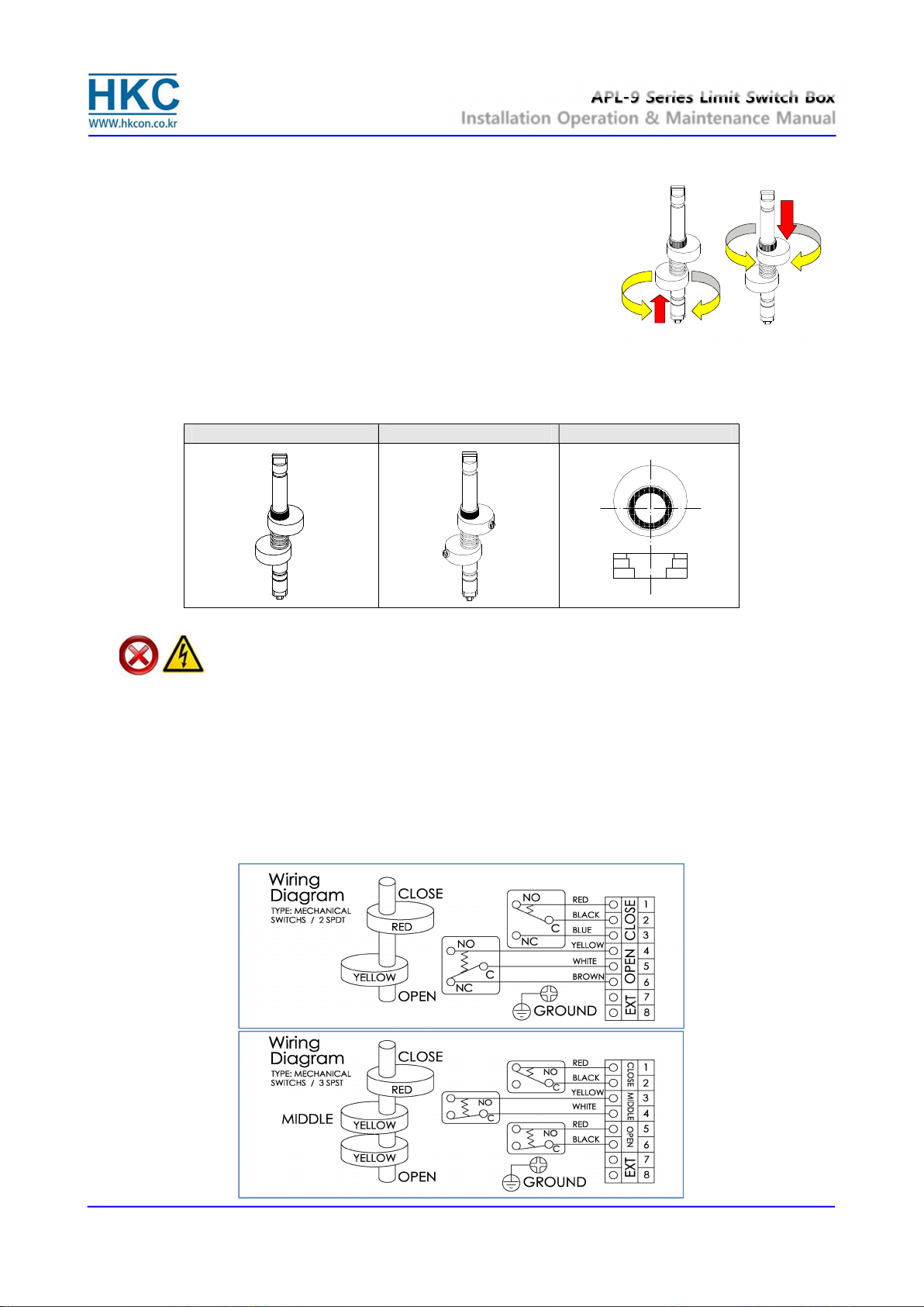
7.3. Setting cam
The color of cams harmonized with position indicator help us to set the cams easily without wiring diagram.
Cams shall be easily set without tool. APL series cams are splined and can be setting lift up or push down the
cam from gear by hand in a seconds without setting tools. Self-locking, spring loading make never slip out of
adjustment.
Note :
Basically, cams shall be set by manufacturer before shipment.
APL-9 Series Limit Switch Box
Installation Operation & Maintenance Manual
Doc No. : HumG-APL9-21 Rev0 Page 7 / 10 Valve Automation Leader HKC
7.3.1. Un-tighten the captive cover bolts with an applicable tool. (Spanner.+ Driver recommended)
7.3.2. Remove the cover carefully.
7.3.3. Open cam setting
① Electric power or air supply of valve actuator on to operate the
actuator fully open
② Lift the bottom yellow cam(optional green cam) up and rotate it
until the switch is activated.
③ And then release it. Cam shall be back into a stable position by
itself.
7.3.4. Close cam setting
① Electric power or air supply of valve actuator off to operate the
actuator fully close
② Push the upper red cam down and rotate it until the switch is activated.
③ And then release it. Cam shall be back into a stable position by itself.
Mechanical switches
Proximity sensors
Splined cam
7.4. Wiring
Danger ;
HAZARDOUS VOLTAGE. No electrical power should be connected until all wiring and limit
switch adjustments have been completely.
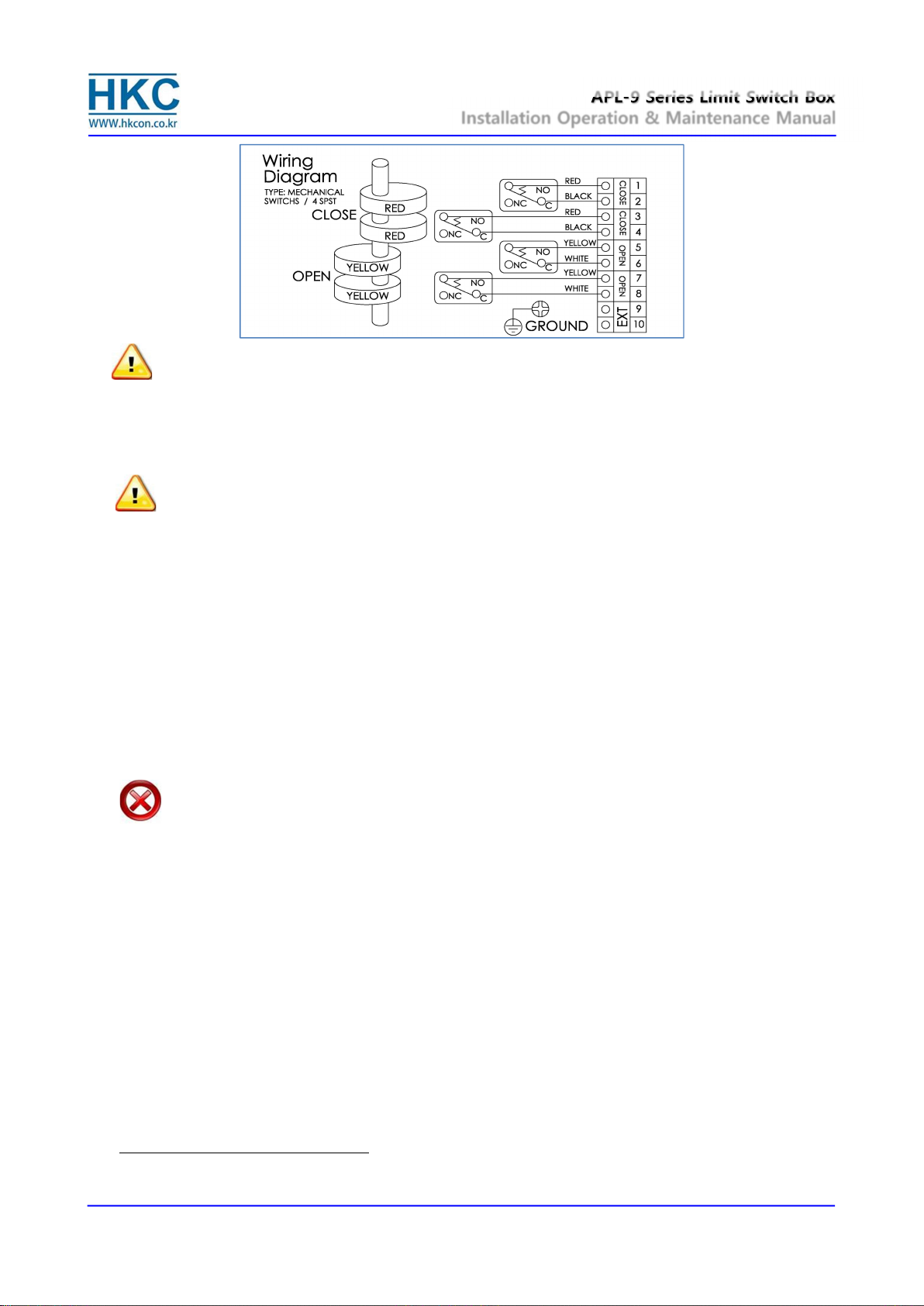
7.4.1. APL limit switch box enclosure feature prewired switches. All user connections are made at a
numbered terminal strip. A wiring diagram, located inside the cover, indicates which terminal numbers
correspond to switch contacts, such as normally open (NO), normally closed (NC), etc. Follow the
wiring diagram and electrical code to connect the switches to your system.
7.4.2. Solenoid valve may also be wired through the APL enclosure. Two auxiliary terminals are included as
standard.
7.4.3. APL limit switch box has two cable entries on the body and supply a blanking plug not a cable gland
which meet the type of protection. Cable gland shall be applied by installer or user.
Open cam Close cam
APL-9 Series Limit Switch Box
Installation Operation & Maintenance Manual
Doc No. : HumG-APL9-21 Rev0 Page 8 / 10 Valve Automation Leader HKC
Note ;
Grounding should be connected until all wiring has been completely.
Wire square for the internal grounding shall be recommended min.2SQ recommended.
Wire square for the external grounding shall be recommended min.4SQ recommended.
Optional wiring diagrams will be provided separately.
8. Maintenance
Caution :
Shut off incoming power or air supply on the valve actuator before maintenance limit switch box.
Be sure that the area is clean before disassemble and maintenance limit switch box. Clean all parts and
housing before re-assemble.
Refers to the part list when ordering replacement or spare parts.
Maintenance, under normal conditions at six month intervals or 100,000 cycle operation. But when conditions
are more severe, more frequent inspections may be required.
8.1. Ensure valve actuator alignment
8.2. Ensure wiring is insulated, connected and terminated properly
8.3. Ensure all screws are present and tight
8.4. Ensure cleanliness of internal electrical devices
8.5. Ensure conduit connections are installed properly and are dry
8.6. Check internal devices for condensation
8.7. Check enclosure seals and verify that the gasket is not pinched between housing
8.8. Visually inspect during open/close cycle
Warning :
Treat cover with care. Gap surface must not be damaged or dirtied in any way
9. Inspection
9.1. The limit switch box should be inspected upon receipt to ensure that no damage has been sustained on
transit.
9.2. Check the item and quantity of products with packing list or related documents.
9.3. Check the limit switch box gasket. Where a damage on it. It caused the corrosion of internal parts.
9.4. Check the adjustment of cams. Cams shall be released when those have been used for a long period of
operating. If do so, they don’t work correctly with switches.
10. Storage
The products must be stored in a clean, cool and dry area. The unit shall be stored with the cover installed and
the cable entry openings sealed. Storage must be off the floor, covered with a sealed dust protector.
11. Trouble Shooting
The following instructions are offered for the most common difficulties encounter during installation and start-
up.
Signal fails to main control room.
11.1. Check the wiring of limit switch box in accordance with wiring diagram.
11.2. Check where the cams or switches are damaged or broken.
APL-9 Series Limit Switch Box
Installation Operation & Maintenance Manual
Doc No. : HumG-APL9-21 Rev0 Page 9 / 10 Valve Automation Leader HKC
11.3. Check the main signal wire from the terminal strip.
11.4. Re-set the limit switch box
12. Tools
12.1. 1 Set Metric Allen key (Hex Wrench)
12.2. 1 Set Screw drivers
12.3. 1 Set Metric spanner
12.4. 1 Wire Stripper long nose
12.5. 1 Needle nose pliers
12.6. 1 Multi Meter (AC, DC, Resistance)
13. Installation and Maintenance Tips
For any installation and maintenance work, the following should be observed :
Caution :
A regular inspection and maintenance performed by qualified and trained personnel.
Observe additional national regulations.
13.1. Check the limit switch box visually. Ensure that no outside damage or changes are visible. The electric
connecting cables must be without damage and wired correctly.
13.2. Cable entries, cable glands, plugs etc. have to be checked for correct tightness and sealing.
13.3. Take care of possible discoloration of the terminals and wires.
13.4. Ensure that all housing covers are handled carefully and that the seals are checked.
13.5. All cable has to be checked.
13.6. If defects which affect the safety are detected during maintenance, repair measures have to be taken
immediately.
13.7. When exchanging parts, seals etc. only original spare parts shall be used.
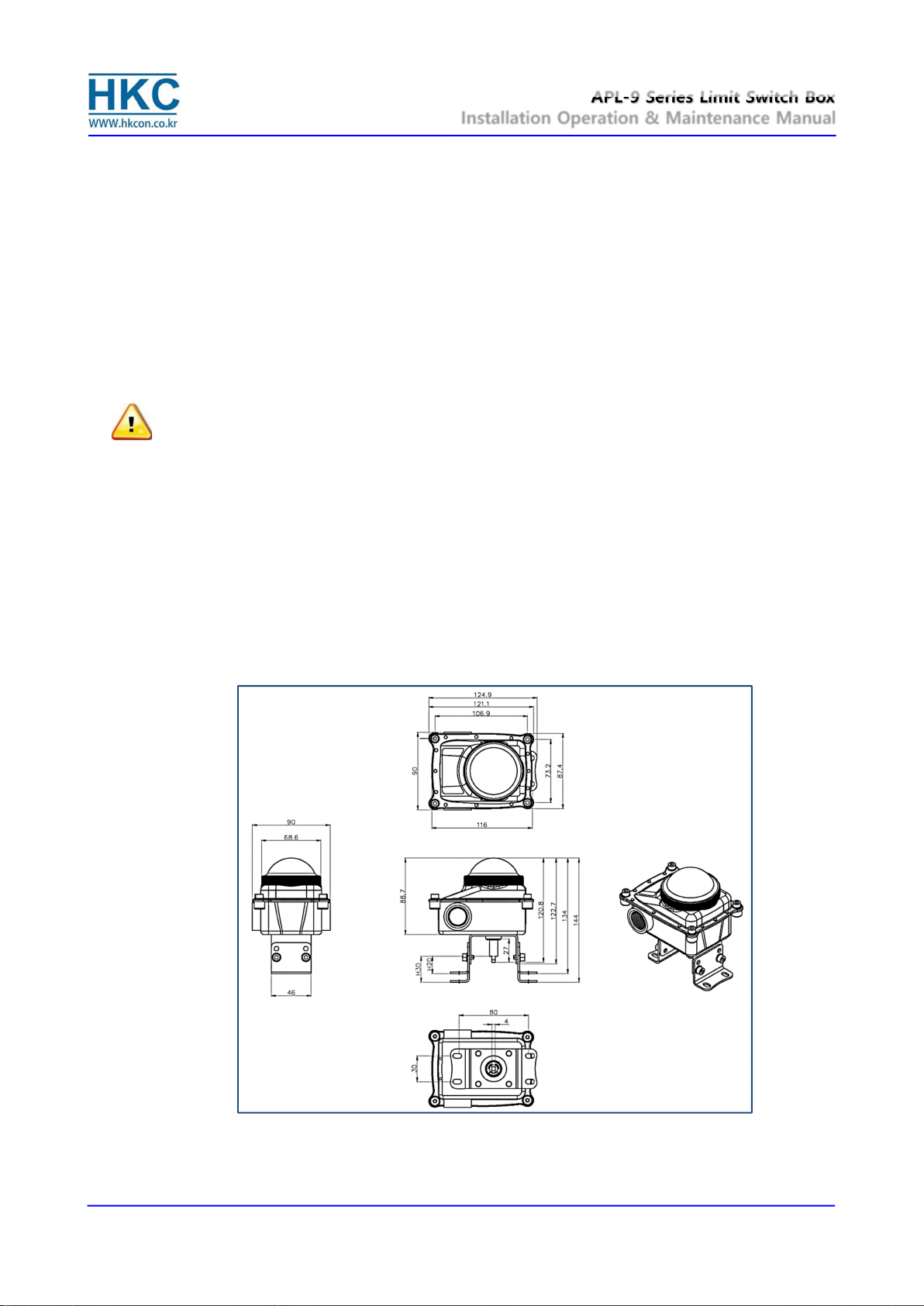
14. Dimensions
14.1. Bracket type S(Standard) : 80X30 H20, 80X30 H30,

APL-9 Series Limit Switch Box
Installation Operation & Maintenance Manual
Doc No. : HumG-APL9-21 Rev0 Page 10 / 10 Valve Automation Leader HKC
14.2. Bracket type O(Option) : 80X30 H20, 80X30 H30, 130X30 H30, 130X30 H40, 130X30 H50
HKC Co., Ltd. 26, Emtibeui 28-ro, Siheung-si, Gyeonggi-do, 15119, Republic of Korea
Head Office & Plant: Tel) +82-31-488-8266, Fax) +82-31-488-8269
Fax) Overseas sales office: +82-31-488-9622, Domestic sales office: +82-31-319-8267
Website www.hkcon.co.kr
This manual suits for next models
1
Table of contents
Other HKC Monitor manuals


