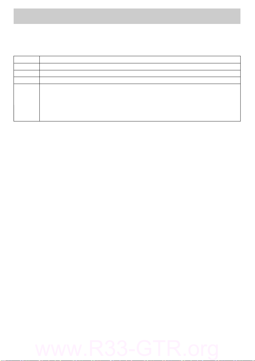
HKS EVC User manual

Instruction Manual
Installation should be performed by a professional.
Prior to installation and use, thoroughly read the
instruction manual. Retain this instruction manual
for later reference.
45003‑AK005
HKS USA Inc
Ver.111506
H K S E L E C T R O NIC S T E C H NO L O G Y
www.R33-GTR.org

Product
Use
Application
Part No.
Remarks
EVC
Boost Controller‑ Automotive Turbocharged Engine
Vehicle that operates on a DC 12V negative ground.
45003−AK005
・
A fuel controller (e.g. F‑CON, AIC, etc) may be needed when raising boost
pressure with the EVC Boost Controller.
・Some vehicles have a fuel cut function when boost is raised. To bypass the
fuel cut function, a unit such as the HKS FCD can be used. When using an
HKS FCD, a fuel controller may be required for additional fuel tuning.
Read this instruction manual prior to installation to ensure safe and correct usage and
optimal product performance,
HKS EVC
Introduction
−1−
The HKS EVC enables the adjustment of the boost setting from inside the vehicle.
Utilizing a stepping motor, it stimulates boost increase and attains the designated
boost value without over‑shooting.
This product was developed to improve engine output and was designed to be used for
racing in a closed circuit. Improving engine output may affect oil and/or water
temperature and oil pressure. To preserve engine performance, regularly monitor
engine conditions before driving.
To use this product on public roads, follow the necessary procedures if there are any
regulations for a tuned/modified vehicle.
●Compact Design
Its compact designed display and stepping motor enables a versatile installation
into the vehicle interior and the engine compartment.
●Wide Boost Range
The boost level can be controlled from baseline boost to 250kPa (36.0PSI).
●Simple Boost Setting
Just directly input the desired boost value to modes A and B, and let HKS EVC
control the boost.
●Return Function
Once EVC is turned off, the boost level returns to the baseline value. For some
vehicles, the boost may become lower than the the stock settings after EVC is off.
●Scramble Function
With the scramble function, the boost can be increased by a designated value above
the set boost value. The increase in boost is obtained while pressing botton① of
the display or the optional external scramble switch (using the provided harness).
The time span of the boost increase after the release of the botton can also be set.
●Dual Boost Mode Settings
A Mode & B Mode are the 2 user specified preset boost level selections. Each mode
can be used for a different purpose or situation.
www.R33-GTR.org

●Dual Offset Mode Settings
If the desired set boost and the actual boost levels do not match, the offset
function can be used to adjust for the difference. The offset of both A Mode &
B Mode can be set individually; therefore, more precise results can be obatined.
●Warning Function
If the boost exceeds the user selectable warning value, the EVC notifies the user
with an audiable beep and visable warning display. Simultaneously, it lowers the
boost to the baseline boost value or by a user preset value. This function prevents
damage to the engine and/or the turbine due to over‑boost.
●Throttle Position Input
With the throttle position sensor signal input, boost characteristics can be
tuned in relation to throttle percentage.
●RPM Signal Input
With the engine RPM signal input, boost characteristics can be tuned in
relation to RPM level.This feature works on engines from 1 to 8 cylinders and
operates up to 12,000 RPM.
●Speed Signal Input
With the vehicle speed signal input, boost characteristics can be tuned in
relation to vehicle speed. This feature works on applications that utilize speed
pulses between 2 to 16 and has a maximum speed capacity of 500km/h.
●Map Adjustment Function
Input of the throttle signal and the engine RPM or vehicle speed signals can draw a
3D map by using 2 these signals as axes. Using the 3D map enables the easy control
of the boost characteristics.(The setting range must be within +/‑120kPa [17.0PSI]
to the baseline boost setting.) This function is user selectable to be on or off.
●Digital Triple Data Meter
3 digital data readings of surge tank pressure, throttle percentage, and engine RPM
or vehicle speed can be displayed.
●Bar Graph Selection
The bar graph display can be set for boost, throttle percentage, engine RPM and
vehicle speed.
●Bar Graph Peak Hold Function
The peak hold function of the bar graph displays and holds the maximum value
achieved for easy instant recognition.
●After Image Display Function
When the boost changes from positive pressure to negative pressure, the maximum
positive boost value is displayed for a few seconds. This function is user
selectable to be on or off.
●Data Memory Function
All set values are saved in the internal memory of the EVC. Therefore, these
settings are not lost when the ignition is off or if the battery is disconnected.
●Exhaust Bypass (wastegate type) Selection
The EVC can work with both internal and external wastegate types.
−2−
www.R33-GTR.org

−3−
●This manual indicates items you need to pay attention to in order to install this
product safely and lists precautions to avoid any possible damage and/or accidents.
●Please contact your dealer for purchasing consumable parts and lost or missing part.
●To use this product on the public road, follow the necessary procedures if there are
any regulations for a tuned vehicle.
●HKS will not be responsible for any damage caused by incorrect use or use after
modification and/or dismantling of this product.
●To use this product on the public road, follow the necessary procedures if there are
any regulations for a tuned vehicle.
●This product was designed for installation and use on a factory vehicle or a vehicle
using other HKS products. The performance and/or safety cannot be guaranteed if this
product is installed onto other vehicles than mentioned above.
●This product is applicable for any vehicle that operates on a DC12V negative ground.
●The specifications of this product, including installation are subject to change
without prior notice.
●This manual is subject to revise without prior notice.
●Pressure Unit of Measure Selection
The unit for of measure for pressure can be selected between kPa or PSI.。
●Dimmer Function
The brightness of the display unit is adjustable.
●Data Lock Function
To prevent accidental change of data settings, the unit can be locked with a code
●Large Multi‑Display
Utilizing a large positive display enables clear day and night viewing. The multi‑
display also enables simultaneous data recognition.
●Digital and Analog Boost Monitoring
The digital data and the bar graph can allow the driver to read and understand the boost
conditions intuitively and visually.
www.R33-GTR.org

−4−
Introduction…………………………………………………………………………………………………1
Index …………………………………………………………………………………………………………4
Safety Precautions…………………………………………………………………………………………5
Parts List……………………………………………………………………………………………………8
Features and Functions……………………………………………………………………………………9
Installation…………………………………………………………………………………………………12
Hose Connection Layout…………………………………………………………………………………12
Wiring………………………………………………………………………………………………………23
Mounting of Components…………………………………………………………………………………24
Post Installation Checks…………………………………………………………………………………25
Operation ……………………………………………………………………………………………………26
Optional Parts List ………………………………………………………………………………………44
Maintenance …………………………………………………………………………………………………44
Trouble Shooting……………………………………………………………………………………………45
Product Specifications……………………………………………………………………………………45
EVC Set‑Up Sheet……………………………………………………………………………………………47
Index
www.R33-GTR.org

−5−
Safety Precautions
Below are symbols used in this manual to highlight areas where .
Warning ‑Risk of severe injury or death may result if
warning is not acknowledged or followed.
Caution ‑Risk of injury to self, damage to vehicle or
property may result if caution is not taken.
Warning
●Make sure to work on the vehilce in a well‑ventilated area to prevent
possible explosion or fire.
●Do not mount the unit where it can distract driving.
●Do not install this product on a 24V vehicle. It is designed for use on
a 12V vehicle.
●Make sure to remove the cable from the negative terminal of the battery
to avoid possible damage to other electronics during installation.
●Make sure to hold connectors when removing them to avoid possible
damage to other electronic parts caused by disconnections or by a
short circuit.
●Stop using the product if any unusual conditions are noticed; it may
cause a fire or an electrical shock. Consult an authorized dealer
immediately.
●Do not operate the EVC while driving to avoid the possiblity of an
accident.
www.R33-GTR.org

−6−
Caution
●Do not install this product by yourself unless you know how to use the
tools and equpiment necessary to safely perform service operations on
your vehicle
●Do not modify, disassemble and/or remodel this product and any of its
attached parts.
●Handle the parts with caution at all times.
●Avoid allowing oil and/or water from entering the unit. It may cause
damage to the engine.
●Prior to installation, make sure that the engine bay temperature has
cooled. Failure to let the engine cool can lead to severe burns.
●Select the appropriate exhaust bypass type. Selecting the wrong type
may cause damage to the vehicle.
●Install the unit away from excessive heat or water to avoid possible
malfunction and damage to the engine.
●Do not tie or bundle a vehicle fuel line with any of the other hoses
and/or harnesses. It may cause severe damage to the vehicle.
●Make sure all connections and wiring are not disconnected, short
circuited or incorrect. It may cause an electrical shock or
damage to the vehicle.
●Used the provided splices and install them to the correct positions. If
not, it may cause serious damage to the vehicle.
●Connect the ground wire onto a good chassis ground. If not, it may
cause damage to the vehicle.
●Insert the vacuum filter and replace it at regular intervals. If not,
it may cause damage to the vehicle.
●When installing the vacuum filter, make sure no oil or lubricants are
existant to cause the hose to come off. If a hose comes off, it may
cause damage to the vehicle.
●Replace the vacuum filter earlier than the regular interval if there
is excessive build up. Dirt build up may cause an inability to control
boost, which may cause damage to the engine.
●Install the air relief valve of the stepping motor downward to avoid
allowing oil and/or water from entering the valve. It may cause
damage to the vehicle.
www.R33-GTR.org

−7−
●Daily check‑up of the vehicle must be done by the owner.
●This manual shows a typical installation. Actual installations may vary depending on
the vehicle application.
●Refer to the factory manual when removing the factory parts.
●Make sure all connections and wiring are correct.
●Do not lose and/or damage any removed parts.
●Use the appropriate tools to tighten bolts and nuts with the correct torque specs to
avoid damage.
●Make sure not to disconnect any wiring from the vehicle when installing the product.
●For a vehicle equipped with a boost control solenoid valve, remove the connector or
hose to deactivate its function.
Caution
●Do not raise the boost excessively. It may cause damage to the engine
and/or the turbocharger.
●The warning function must be activated to prevent any damage to the
engine caused by over‑boosting.
●Do not test the product on the vehicle on a public road.
●If this product or the vehicle does not perform properly, consult your
authorized dealer immediately.
●Do not repair the product by yourself.
●If an unusual noise, smell and/or vibration is noticed, take the
necessary measurements referring to the user's manual.
●Insulate wires left on the vehicle after removal of the product. It
may cause damage to the electronic parts.
www.R33-GTR.org

−8−
Parts List
Instruction Manual
Hardware Set
M6Bolt and Nut
M6Flat Washer
M6Lock Washer 1 each
Double‑Sided Tape
Splice Tie Wrap
Hose Clamp
Vacuum FilterT‑Fitting
4mm Hose
EVC Stepping Motor Extension Harness
EVC Display Unit
1
111 1
11
1 1Set 2
3 1 1Set 1Set
2 3 4
58
9 10 11 12
13 14
18
15 16
17
2.7m
φ6用
100mm…………Qty.5
1m
4‑4‑4mm 4mm ,6mm 1 each
1.0m
● Tools required for installation: Test Light or Volt Meter, Screwdriver, Socket Wrench,
Wire Cutters, Hose Cutters and Pliers.
● Retain all unused parts.
Power Harness
1
6mm Hose
1m
1801‑SA033
1801‑SA004
6mm……
4599‑RA016
4mm……
4599‑RA017
Main Harness
1.5m
Scramble Harness Input Signal Harness
12
1m1.5m
6 7
(1 for Speed & RPM,
1 for Throttle signal)
取付けは、必ず専門業者に依頼してください。
取付け前及びご使用前に必ずお読みになってください。
本書はお読みになった後も、本製品の側に置いてご活用ください。
ご使用中にわからないことや、不具合が生じた際に便利です。
21207‑023T
1998年○月○日発行
Ver.3‑1.0
E L E C T R O NI C VA L V E C O N T R O LL E R
HKS ELE CT T R O N IC S TE C H NO L O G Y
1
19 20
1
取付けは、必ず専門業者に依頼してください。
取付け前及びご使用前に必ずお読みになってください。
取付けは、必ず専門業者に依頼してください。
取付け前及びご使用前に必ずお読みになってください。
取付けは、必ず専門業者に依頼してください。
取付け前及びご使用前に必ずお読みになってください。
本書はお読みになった後も、本製品の側に置いてご活用ください。
ご使用中にわからないことや、不具合が生じた際に便利です。
取付けは、必ず専門業者に依頼してください。
取付け前及びご使用前に必ずお読みになってください。
本書はお読みになった後も、本製品の側に置いてご活用ください。
ご使用中にわからないことや、不具合が生じた際に便利です。
取付けは、必ず専門業者に依頼してください。
取付け前及びご使用前に必ずお読みになってください。
本書はお読みになった後も、本製品の側に置いてご活用ください。
ご使用中にわからないことや、不具合が生じた際に便利です。
車種別配線位置図
Connecting Manual
11
Quick Manual Function Manual
EVC機能解説
エンジン回転数
ブースト
●オフセットとは?
オフセットとは、AモードまたはBモードで設定した目標ブーストに対して実際のブーストがその
圧にならない場合に、値を調整することによって目標ブーストに安定させることができる機能です。
オフセット値を上げると実際のブーストは上がり、オフセット値を下げると実際のブーストは下
がります。排気バイパスタイプがスイングバルブタイプ、ポペットバルブタイプのどちらでも、
この関係性は変わりません。
目標ブースト(例:100kPa)
実際のブースト
(例:80kPa)
図1.オフセット100%の場合
エンジン回転数
ブースト
目標ブースト(例:100kPa)
実際のブースト
(例:100kPa)
図2.オフセット120%の場合
●スクランブルブーストとは?
スクランブルブーストとは、AモードまたはBモードで設定した目標ブーストに対して、設定した
ブーストを一定時間プラスことができる機能です。
スクランブルブースト設定モードで設定したブースト値に、実際のブーストがなるわけではあり
ませんので注意してください。
図3.スクランブル機能未使用の場合
エンジン回転数
ブースト
目標ブースト(例:80kPa)
実際のブースト
(例:80kPa)
エンジン回転数
ブースト
●ワーニングとは?ドロップブーストとは?
ワーニングとは、設定したワーニングブーストに対して実際のブーストがその値を超えた場合に、
画面および音で警告をするとともに目標ブーストを下げる機能です。
ドロップブーストとは、ワーニング作動時に目標ブーストの下げ幅を決定できる機能です。ドロ
ップブーストOFFではノーマルブーストに下がります。
ドロップブースト設定モードで設定したブースト値に、実際のブーストがなるわけではありませ
んので注意してください。
ワーニングブースト(例:120kPa)
ノーマルブースト
(例:60kPa)
図5.ドロップブーストOFFの
ワーニング作動時
実際のブースト
(例:60kPa)
エンジン回転数
ブースト
ワーニングブースト
(例:120kPa)
ドロップブースト設定値
(例:20kPa)
図6.ドロップブースト設定後の
ワーニング作動時
実際のブースト
(例:80kPa)
図4.スクランブル機能使用の場合
エンジン回転数
ブースト
目標ブースト
(例:80kPa)
スクランブル
開始ポイント
スクランブル
ブースト設定値
(例:20kPa)
実際のブースト
(例:100kPa)
目標ブースト
(例:100kPa)
目標ブースト
(例:100kPa)
E05121−K000??−00
Ver.
3−1.
01
スクランブル設定時間
操作クイックマニュアル
1.イグニッションスイッチを"ON"にする
エンジンキーを回してイグニッションスイッチを"ON"にしてEVCおよび車両から異音・異臭
がないことを確認してください。問題がなければそのままエンジンをかけてください。
E05121−K000??−00
Ver.3−1.
01
操作マークの説明 :短く押す :ボリュームを回す :1秒以上押し続ける
2.圧力単位を設定する
初めて使用する場合は、自動的に下図のような画面が表示されています。
ボリュームを回してブースト表示の圧力単位をPAS(kPa)またはPSIから選択してください。
設定が終了したらボリュームを押して決定してください。
2.排気バイパスタイプを設定する
ボリュームを回して排気バイパスタイプの設定を行ってください。
アクチュエータを使用するスイングバルブタイプの場合「ーS−」を、ウエストゲートを使用
するポペットバルブタイプの場合「ーPー]を選択してください。
設定が終了したらボリュームを押して決定してください。
3.ノーマル最大ブーストを設定する
EVC取付け後のノーマル最大ブーストの設定を行ってください。
手動での設定を行う場合は、ボリュームを回してノーマル最大ブーストを入力してください。
www.R33-GTR.org

−9−
Features and Functions
1. Features
1.Button ①
Use this button to activate the scramble function in the standard mode. While pressing
this button, the scramble function is activated. When the scramble function's timer is
set,the function starts working when the button is released. If the set value is blinking
in the speed axis set mode, RPM axis set mode, throttle axis set mode, map correction
boost A/B set mode, or map offset A/B set mode, this button is used to select between the
set axis and the set value.
2.Volume Knob
In the standard mode, pressing the volume knob for more than 1 second resets the peak
value. Turn the knob left to switch to boost mode A and turn right to the mode B.
Pressing the volume button in each mode makes the set value blink or turn it on. When
the set value is blinking, turning the volume knob to the right increases the value; and
turning it to the left decreases the value. In other modes (aside from standard mode),
when the value is blinking, turning the button switches the modes in each mode group.
3.Button ②
In the standard mode (when the A/B boost value is not being set) press this button for
more than 1 second to switch the EVC on or off. When the power is on, the EVC control
becomes active. When the power is off, the vehicle returns to the standard boost value
which is not controlled by the EVC. When the set value in each mode is blinking,
pressing this button switches the mode group.
4.Main Harness Connector
This main harness connects the power harness, extension harness, and each signal harness.
5.Scramble Harness Connector
This scramble harness connects the optional external scramble switch.
6.Easy Writer Connector
This connector is for PC communication to make settings with the HKS Easy Writer. (Optional)
1.Button ①
2.Volume Knob
3.Button ②
6.Easy Writer Connector(5PIN)
4.Main Harness Connector(3PIN)
5.Scramble Harness Connector(2PIN)
Rear
Panel
Front
Panel
www.R33-GTR.org

−10−
1.Digital Display(S)
In this display, the preset warning value, preset A/B boost values, scramble
countdown time, mode name, or wastegate type is shown. The pressure is shown as
○○○(kPa) or ○○.○(PSI), the scramble countdown time is shown as ○○(Sec), the
mode name is shown as ○○○(MODE), and the wastegate type is shown as −○−.
Standard Mode :Set Warning Value
Standard Mode(A/BBoost Settings) :Preset A/BBoost Values
Standard Mode(Scramble Function) :
Scramble Countdown Time
Each Setting Mode :Mode Name
Opening Screen :Wastegate Type
2.Speed / RPM Display
In this display, the value for each axis of the following mode is shown; Speed Axis
Set Mode, RPM Axis Set Mode, Map Correction Boost A/B Set Mode and Map Offset A/B
Set Mode.
3.Throttle Display
In this display, the value for each axis of the following mode is shown; Throttle Axis
Set Mode, Map Correction Boost A/B Set Mode, and Map Offset A/B Set Mode.
4.Unit Display
In this display, the 4 units of measure(kPa, PSI, S, V) are shown for each mode:
kPa is displayed for manifold pressure
PSI is displayed for manifold pressure
S is displayed in the Scramble Time Set Mode
V is displayed in the Full Throttle Voltage Set & Closed Throttle Voltage Set Modes
5.Digital Display(L)
In this display, the manifold pressure, set value, or name is shown as ○○○(kPa) or
○○.○(PSI):
In the Standard Mode the boost value is shown
In each Set Mode, the set value or mode name is shown
6.Indicator Display
This display shows the following:
In the Standard Mode and the peak value is displayed, "P.H." is iluminated.
In the Standard Mode and the map function is being used or in the Map Set
Group, "MAP" is iluminated.
In each mode where the set value is being changed, "SET" is illuminated.
In each mode where the set value is being selected, "SEL" is illuminated.
In the Scramble Boost Set Mode, Scramble Time Set Mode, or if the scramble function
is activated, "SBC" is illuminated.
In the Warning Boost Set Mode, Drop Boost Set Mode, or if the warning function is
activated, "WRN" is illuminated.
2.Display
2.1.Digital Display
1.Digital Display (S)
6.Indicator Display
7.Bar Graph Display
8.Selection Display
4.Unit Display
5.Digital Display(L)
2.Speed / RPM Display
3.Throttle Display
www.R33-GTR.org

Note
・The LCD of the display unit may have a black line. This is caused by static electricity,
and it does not affect the functions or performance of the unit. To remove the line,
wipe the display with an antistatic cloth or a cloth with the antistatic solution.
−11−
2.3.Scramble Boost Activated
2.4.Warning Function Triggered
After the unit beeps, the bar graph
and the SBC indicator will blink.
After the unit beeps, the bar graph and
the WRN indicator will blink.
7.Bar Graph Display
In this display, a bar graph of the following can be shown: manifold pressure, speed,
RPM, throttle percentage opening, set value, or axis number. In the Standard Mode, you
can select between the manifold pressure, speed, RPM, and throttle percentage opening
for real‑time display.
8.Selection Display
The indicators of A and B show the selected preset boost setting in the Standard Mode.
In the Offset A/B Set Mode, Map Boost A/B Set Mode and Map Offset A/B Set Mode, the
current preset value is shown. The indicator of SPD, REV, and THR show the input signal
currently used for the correction map in the Standard Mode, Map Boost A/B Set Mode and
Map Offset A/B Set Mode. In the Speed Axis Grid Point Set Mode, RPM Axis Grid Point
Mode and Throttle Axis Grid Point Set Mode, each corresponding signal is shown.
2.2.Start‑Up
After the unit beeps once, the
wastegate type appears on the digital
display (S), and the preset boost value
appears on the digital display (L).
Beep
Beeeeeeep....
BeepBeepBeep....
www.R33-GTR.org

−12−
Installation
(1)Disconnect the negative terminal from the battery.
●This manual shows a typical installation. Actual installation may vary depending on
the vehicle application.
1.Removal of Battery Terminal
2.Hose Connection Layout
(1)With consideration to the hose and harness lengths, determine the appropriate hose
connection layout and mounting in regards to the display unit and stepping motor.
Advice
・Leave some slack for the harness & hoses to avoid tension during engine movement.
・Do not install any components in high temperature areas.
●This product was designed to be used with vehicles using a DC12V
negative ground. Do not use on a vehilce with a 24V ground.
Warning
1. Removal of Battery Terminal …………………………………………………………………… 12
2. Hose Connection Layout
2.1. Stepping motor and 4mm Hose ……………………………………………………………
13
2.2. Swing Valve Type ………………………………………………………………………… 14
2.3. Poppet Valve Type ………………………………………………………………………… 18
2.4. Twin Turbo(Swing Valve) ……………………………………………………………… 20
2.5. 4mm Hose Connection Layout(Swing Valve) …………………………………………
21
3. Wiring ……………………………………………………………………………………………… 23
4. Mounting of Components …………………………………………………………………………… 24
5. Post Installation ………………………………………………………………………………… 24
www.R33-GTR.org

(4)Use the remaining 4mm hose to connect the
T‑Fitting to 4mm vacuum filter on Nipple B
of the EVC Stepping Motor.
Advice
・Make the hose length short as possible
・Do not put and oil and/or lubricants on
or in the hose and vacuum filter
・Nipples of the EVC stepping motor must be
facing upward to avoid any oil or water
from entering.
(1)Cut the 4mm and 6mm Hose and connect them
to the respective 4mm and 6mm vacuum
filters as shown in the diagram on the left.
Advice
・Cut the 4mm and 6mm hose to different
lengths so that the vacuum filters are
not in contact with each other.
・Do not pu any oil and/or lubricants on
or in the hose and vacuum filter.
−13−
2.1.Stepping Motor and 4mm Hose
6mm Vacuum Filter
4mm Vacuum Filter
4mm Hose
5cm Length
6mm Hose
8cm Length
Hose Clamp
Intake
Manifold
Intake
Manifold
Remove Here
Fuel
Pressure
Regulator
4mm Hose
5cm Length
4mm Hose
Fuel Pressure
Regulator
4mm Hose
4x4x4 mm
T‑ Fitting
Intake
Manifold
4mm Vacuum Filter
NippleB
EVC Stepping Motor
Fuel Pressure
Regulator
4mm Hose
4x4x4mm
T‑Fitting
(3)Cut a 5cm length portion of the included
4mm hose and connect it the the T‑Fitting
as shown in the diagram on the left.
(2)Remove the hose that connects the intake
manifold and the fuel pressure regulator
from intake manifold side.
www.R33-GTR.org

−14−
2.2.Swing Valve Type
Before Installation(Basic Connection Layout)
After Installation
Turbine
Actuator
Compressor
Airflow Meter
Air Filter
Nipple①
6mm Hose
Throttle Valve
Intake
Manifold
Fuel Pressure
Regualtor
2.2.1.For Applications without a Boost Solenoid Valve
Turbine
Actuator
Compressor
Airflow Meter
Air Filter
Nipple①
6mm Hose
Throttle Valve
Intake
Manifold
Fuel Pressure
Regulator
4mm Hose
4x4x4 mm
T‑Fitting
6mm Hose
Vacuum Filter
EVC Stepping Motor
www.R33-GTR.org

−15−
Hose Clamp
Hose Clamp
Hose Clamp
Hose Clamp
Nipple①
Nipple①
NippleO
Actuator
EVC Stepping
Motor
6mm Vacuum Filter
6mm Hose
Factory 6mm Hose
Advice
・Do not put any oil and/or lubricants on or in the hose and vacuum filter.
・Use the hose clamp to connect the 6mm hose and the 6mm vacuum filter.
・If the factory hose's length is not long enough to connect, use the optional
oil‑resistant hose. This optional oil‑resistant hose is available separately.
(Refer to the Optional Parts list in this manual)
(3)Connect the factory hose, which is still
connected to the actuator, to the EVC
Stepping Motor's NippleO.
(2)Connect Nipple① and the EVC Stepping
Motor's 6mm vacuum filter using the
included 6mm hose.
(1)Remove the hose which connects the actuator
and Nipple① from the compressor side.
Note
・The position of Nipple① on the compressor
may vary depending on vehicle.
・Reuse the factory hose clamp.
www.R33-GTR.org

−16−
2.2.2.For Applications with a Boost Control Solenoid ‑ 1
Before Installation(Basic Connection Layout)
After Installation
6mm Hose
Turbine
Actuator
Boost Control
Solenoid Valve
Compressor
Airflow Meter
Throttle Valve
Air Filter
Intake
Manifold
Fuel Pressure
Regulator
6mm Hose
4mm Hose
4x4x4 mm
T‑Fitting
6mm Hose
Turbine
Actuator
Boost Control
Solenoid Valve Compressor
Airflow Meter
Throttle Valve
Air Filter
Intake
Manifold
Fuel Pressure
Regulator
Rubber Cap
Rubber Cap
EVC Stepping Motor
●Bypass the function of the boost control solenoid valve by removing the connector or
hose.
Vacuum Filter
www.R33-GTR.org

−17−
Before Installation(Basic Connection Layout)
After Installation
2.2.3.For Applications with a Boost Control Solenoid Valve ‑ 2
6mm Hose
Turbine
Actuator
Boost Control
Solenoid Valve
Compressor
Airflow Meter
Throttle Valve
Air Filter
Intake
Manifold
Fuel Pressure
Regulator
6mm Hose
4mm Hose
4x4x4 mm
T‑Fitting
6mm Hose
Turbine
Actuator
Boost
Control
Solenoid
Valve
Compressor
Airflow Meter
Throttle Valve
Air Filter
Intake
Manifold
Fuel Pressure
Regulator
Rubber Cap
Rubber Cap
EVC Stepping Motor
●Bypass the function of the boost control solenoid valve by removing the connector or
hose.
Vacuum Filter
www.R33-GTR.org

−18−
2.3.Poppet Valve Type
Before Installtion
After Installation
8mm Hose
Turbine
Compressor
Airflow Meter
Throttle Valve
Air Filter
Intake
Manifold
Fuel Pressure
Regulator
6mm Hose
6mm Hose
4mm Hose
4x4x4 mm
T‑Fitting
6mm Hose
Turbine
Compressor
Airflow Meter
Throttle Valve
Air Filter
Intake
Mainfold
Fuel Pressure
Regulator
EVC Stepping Motor
6x8x6mm T‑Fitting
Upper Port
Wastegate
Wastegate
Attach nipple
(L or straight nipple)
to upper
port
To install this unit on to a poppet valve equipped vehicle, the hose set for the poppet
type is necessary.
Vacuum Filter
www.R33-GTR.org

(3)Connect the 6mm Vacuum Filter of the EVC
Stepping Motor's NippleⅠ to the T‑Fitting
using the 6mm hose.
Advice
・Do not put any oil and/or lubricants on
or in the hose or vacuum filter.
(1)Cut the 8mm hose at the point of 5cm from
the compressor's Nipple①. Remove the
remaining 8mm hose and 8mm nipple from the
wastegate.
Note
・The position of Nipple① on the compressor
may vary depending on the vehicle.
−19−
Nipple①
Nipple①
NippleⅠ
Cut Here
5cm Length
Wastegate
6x8x6 mm T‑Fitting
6mm Vacuum Filter
6mm Hose
6mm Hose
6mm Nipple
Hose Clamp
Hose
Clamp
Hose Clamp
Note
・Use the hose clamp to connect the 6mm hose and the 6mm nipple.
(4)After removing the 8mm nipple from the
wastegate, install the 6mm nipple (straight
or L‑Shaped).
(5)Install the included 6mm hose as shown in
the diagram on the left.
(2)Install the 6x8x6mm T‑Fitting using the 8mm
Hose Clamp.
Note
・Use the 6x8x6mm T‑Fitting and 8mm Hose
Clamp included in the hose kit for the
poppet valve type applications.
www.R33-GTR.org
This manual suits for next models
1
Table of contents
Popular Automobile Electronic manuals by other brands

Perfect Tuning
Perfect Tuning MS3Pro-PNP user manual

Audiovox
Audiovox Pursuit PRO 9845 installation manual

Rear view safety
Rear view safety RVS-5350-W Product manual installation & instructions

Eplus
Eplus P436.CE Assembly manual

Auto Page
Auto Page BPS-4 Mounting template

TypeS
TypeS BT57799 Care & use instructions