HKS DMR-150D User manual
1 2
Thank you for your purchase of HKS DMR (Drive Multi Recorder).
This manual indicates items that require attention in order to install this product safely and lists precautions
to avoid any possible damage and/or accidents.
●HKS DMR is a device to record and view images to make drivers more aware of safe driving and accident
prevention.
●This product does not guarantee to record all images involved in an accident. Also, the sensor may not
record any image if the impact is too small.
●Do not use any recorded images for improper purposes. Recorded images may contain scenes which
constitute an invasion of privacy. HKS will not be responsible for any case caused by improper use of the
image recorded by this product.
●HKS will not be responsible for any damage caused by incorrect installation and/or use of this product.
●HKS will not be responsible for any causalities and/or property damage caused by an accident. Also, HKS
will not be responsible for any damage or loss of data caused by incorrect use and/or malfunction of this
product.
●HKS will not be responsible for the expense of the production installation and/or removal and the loss
caused by the period the vehicle cannot be used.
●The specifications of this product are subject to be changed without notice.
●This manual may contain information which is different from the actual product since it was prepared
ahead of the product release.
●This manual is subject to be revised without notice.
WARNING 3
CAUTION 6
SD MEMORY CARD PRECAUTIONS 8
GPS 11
PRODUCT INTRODUCTION 14
PACKAGE CONTENTS 17
NAME AND FUNCTION 19
PRODUCT STRUCTURE 21
INSTALLATION 22
INSTALLATION OF CONSTANT POWER SUPPLY UNIT 30
OPERATION 33
INSTALLATION OF VIEWER SOFTWARE 43
PRODUCT SPECIFICATIONS 46
TROUBLESHOOTING 49
MAINTENANCE 51

3.Clean the mounting surface to prevent the unit from falling off.
If the mounting surface is not clean, double-sided tape cannot be affixed properly and the unit cannot
be secured to the surface that may cause malfunction or damage to the product.
4.Do not use inapplicable components which are not listed in the package contents.
Use of inapplicable components may cause damage to the product or accident. HKS will not be
responsible for any damage or loss caused by the use of inapplicable components.
1.Do not operate this product or stare at this product while driving.
Operating this product or staring at this product while driving may cause accident. Park a vehicle in
safe place when operating this product.
2.Do not mount the unit where it may distract driving.
Secure cables using the provided clips to avoid possible accidents.
Using this product out of the specified voltage range may cause fire and/or damage to the product.
Use this product with input voltage DC12-24V.
5.Use this product with input voltage DC12-24V.
Using inapplicable fuse may cause fire and/or damage to the product. Contact your dealer when
replacing fuses.
8.Use the specified ampere fuse when replacing.
Failure to do so may result in a fire, electric shock, and/or product damage.
10.Avoid foreign objects from entering to the product.
Disconnected connectors may cause damage to other electronics parts and/or a fire caused by a short
circuit.
7.Hold connectors when removing them to avoid damage.
Failure to do so may result in a fire, electric shock, and/or product damage.
9.Avoid dropping or subjecting this product to excessive impacts.
Damaged and/or broken cables may cause fire or damage to this product by short circuit.
6.Take extra care when handling cables.
Indicates risk of serious injury and/or possible death.
3 4
The following precautions for use of this product are to prevent possible accidents and/or
injuries and for proper use.
4.Do not mount any other device around the area this product is mounted.
If any other device is mounted, reflection of said device on the windshield may be recorded.
13.Do not subject the product to excessive heat to dry any wet portions.
Do not use a dryer, microwave, oven, and/or stove to dry wet portion to avoid explosion,
deformation, and/or damage to the product. Contact your dealer for proper way of handling.
2.Clean the windshield and lens of this product on a regular basis.
If the windshield and/or lens of this product are not clean, the recorded image may not be sharp
enough. Wipe the window and lens with a soft cloth regularly.
14.Remove the product from a vehicle on an extremely hot or cold day.
12.Install the product away from excessive water/moisture.
This product is not a waterproof. Excessive water/moisture may cause fire, electric shock, and/or
damage to the product.
Leaving the product in a vehicle for a long time on an extremely hot or cold day may damage product.
Especially during summer, the temperature in a car may be extremely hot; it may cause malfunction of
the main unit and/or SD memory card.
15.Stop using the product if any unusual situations such as unusual noise, odour, etc. are
noticed, consult the dealer immediately.
Failure to do so may result in a fire, electric shock, and/or other electronics parts damage.
1.Use this product only as specified and only for the purpose described in this manual.
3.Image quality may vary depending on shades of the windshield's color, location, and/or
light source.
The recorded image may be unclear or distorted if the windshield's color is dark, or there are foreign
objects on the windshield. Also, a sudden change of the ambient brightness, heavy backlight, and/or
darkness may affect the image quality.
Modification, disassembling, and/or remodeling the product may cause loss of data, fire, electric
shock, and damage to the product. In this case, after-sales service cannot be provided. Contact your
dealer for repair or inspection.
11.Do not modify, disassemble, and/or remodel the product. Indicates risk of serious injury or property damage.
5 6
The following precautions for use of this product are to prevent possible accidents and/or
injuries and for proper use.
9.Do not use water, alcohol, thinner, and/or benzene to clean this product. Always use a
soft dry cloth to clean.
10.Using this product for a long time when the ignition switch or ACC is on without starting
the engine may cause the battery to run out.
7.Connect the power cable and other connectors properly.
Improper connection may cause malfunction of the product such as loss of data from the SD memory
card.
8.Route the power cable away from the antennas and/or conductors of other devices.
Failure to do so may cause poor reception.
6.Check the recorded images on a regular basis.
To maintain this product and the SD memory card, check the recorded images regularly.
5.LED traffic signals blink at high speed which is invisible to the human eye; therefore, the
image of the signal may not be recorded as it blinks. If the signal was not recorded, de-
termine from the situation/circumstances using images before and after.
HKS will not be responsible for any incident caused by the fact that the LED signals cannot be recorded.
This product uses a SD memory card to record images.
Carefully read the following precautions for proper use of the memory card.
Viewer software installer and operation manual are stored on in the provided SD memory
card.
Make sure to backup each file to the hard disk of a PC or another memory device before
using this product.
HKS will not be responsible for any damage to the memory card or loss of data.
7 8
4.Do not share cards with other devices (such as, Navigation systems, digital camera,
audio players etc.)
3.Do not remove memory card whilst product is in use.
In order to prevent damage to this product, the memory card and a possible loss of data, please
ensure the unit is switched off and all LED gone out before removing the SD memory card.
5.Do not leave near magnets or areas with strong magnetic field.
This can lead to damage or loss of data.
7.Back up any data that must be kept for long periods of time.
When SD memory card capacity is full, the oldest data will be overwritten. Any data that needs to be
saved should be backed up onto an alternative medium such as hard disc or CD-R.
8.Check that the SD memory card is not in write protect mode before use.
If the card is in write protect mode, the unit cannot function correctly.
6.Keep out of the reach of children.
Choking hazard.
1.Check the condition of the memory card regularly. Replace when it is degraded.
When using the SD memory card for an extended period of time, new data cannot be saved on it.
Check the card's condition regularly.
It is recommended to format the memory card once a month.
When formatting a SD memory card, backup the data in the SD memory card to the computer if
necessary.
When formatting a SD memory card, select a regular format not a quick format. When using an OS
standard format tool, clear the check box for "Quick Format" on the window.
When the memory card cannot be used properly, replace it with a new recommended SD memory
card. The SD memory card needs to be changed roughly once a year.
※When formatting the memory card, format the file system to FAT or FAT32. If not, the SD memory
card cannot be recognized by this product.
2.Use the provided SD memory card.
If any damage or malfunction of the provided SD memory card were found within the warranty period,
the memory card can be replaced with no charge. After the warranty period, replace the memory card
with a new recommended memory card.
When formatting the SD memory card, the setting of the DMR is initialized. To restore
to the previous setting, copy the setting saved as "blackbox_setup.dat" from "setup"
folder in the SD memory card to the hard disk of the PC.
9 10

1.GPS shows a position where it is at least 15m different from the correct position.
Due to the characteristics of radio waves, the GPS may show more than 100m difference or be out of
range depending on weather and/or circumstances.
2.When using this product for the first time or not using for an extended period of time,
it may take time to obtain the current position.
It may take 5 ~ 30 minutes.
3.Optimum operation temperature range is from 0℃ to 50℃.
Since temperature inside a vehicle may be extremely high or low in midsummer or midwinter, make
sure to maintain the temperature inside a vehicle to be the same as ambient temperature to prevent
malfunction of the GPS.
4.Glass which could block radio waves, such as UV reflective glass, dark colored light
shields may cause poor reception of the GPS.
Do not install the product around these shields.
11 12
6.When a vehicle is moved to another position while the GPS wave cannot be received,
it will take longer to obtain the current position.
7.Speed and distance are calculated by GPS signal. The measured values may be different
from the actual values due to the condition of the reception.
8.Recorded images are saved as files named from the date recorded. When images were
recorded while the GPS wave cannot be received, the file name may not reflect the cor-
rect recorded date.
5.Other devices that generate electromagnetic wave may cause poor reception of the GPS.
When using this product with a remote controlled engine starter, security system, digital audio system,
GPS navigation system and/or another device utilizing GPS system, radio wave interference may
occur, and reception of GPS wave may be unstable or very poor.
13 14
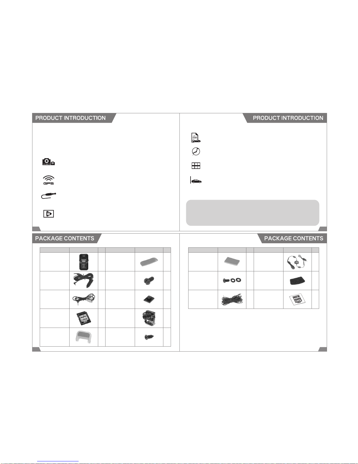
HKS DMR (Direct Multi Recorder) is the image recorder for automobiles. This product is to record the
voice, position, speed, and motion during driving by a high quality built-in camera, G-sensor, GPS
receiver, and second camera. This product can obtain information in road traffic accidents. Having a
recording of the moment can be very useful in clarifying the situation. HKS DMR can assist safe driving.
◆PRODUCT FEATURES
1.Recording of the front and behind the vehicle and vehicle interior
The built-in camera records the front of the vehicle, and a second camera also
records additional images of the vehicle's front and behind the vehicle and vehicle
interior.
2.Saving the driving log by the built-in GPS receiver
The high quality built-in GPS receiver can record the route, speed, and position
during driving.
3.File Viewer Function
Data recorded in the DMR can be viewed on a monitor in real time or later using the
external output AV cable. DMR settings are normally set by using the special software
on a computer but it is also possible to setup using a monitor.
4.Protecting the recorded images
All recorded data can be protected by setting a password on the provided view
software. The password can prevent unauthorized access to recorded data. All
recorded data are encrypted; therefore, ordinary media player cannot play the data.
5.Creating Event Report
Create an event report displaying the picture, G sensor figures and GPS location.
It's also possible to place a comment.
6.Recreating the driving route
Driving route can be traced using Google Earth.
7.16 Frame Multi Capture
The Viewers Multi frame capture feature, display 16 frames to analyze events
accurately.
8.Recording while a vehicle is parked for security
By connecting to the constant power supply, it is possible to leave the unit on to use
the main camera and 2nd camera as security cameras while the vehicle is parked.
The constant power supply unit has an On/Off switch and also an auto-cut feature
which prevents the battery from discharging too much.
● System Structure: ○ CPU ・ Pentium 3 or greater ○ RAM ・ 512MB or more
○ Hard Disk ・ 10GB or more ○ Internet Accessible ○ Display Resolution ・ 1,024 x 768 or higher
● Microsoft Windows XP SP2 or later / Windows Vista / Windows 7
Internet Explorer 7.0 or later.
Attached Software: Hardware Requirement for HKS DMR Viewer
15 16
17 18
DMR Main Unit
Description Image Qty Description Image Qty
AV Cable
Power Cable
(4m) Screw (L)
Second Camera
Double-sided Tape
(Spare)
Cable Clip
SD Memory Card
(8GB)
1
1
1
1
Fitting Bracket 1
1
6
2
1
Screw (M) 3
Description Image Qty Description Image Qty
Power/AV Cable
(6.5m) Instruction Manual
1 1
1 2
1 1
Constant Power
Supply Unit
Fixture Tape
Constant Power
Supply Unit
(3.5m)
Fitting Accessories
for Second Camera
(Spare)
Double-sided Tape
for Second Camera
(Spare)
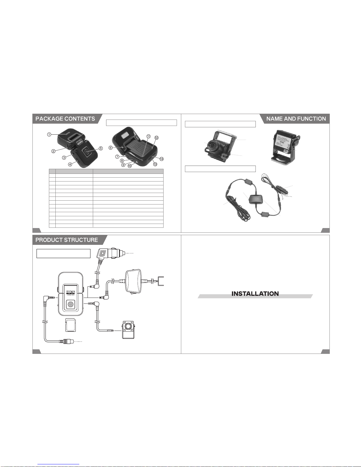
Fitting Bracket
Lens
Screw (S)
Power/AV Connector
Fuse
Power Plug
Input Voltage
Switch
Power Switch
19 20
SECOND CAMERA
DMR MAIN UNIT
CONSTANT POWER SUPPLY UNIT
1 GPS ModuleReceive the GPS signals.
2 ScrewFix and adjust the installation angle.
3 AV OUT PortOutput the viewer mode.
4 Multi ButtonOperate the view mode.
5 Camera LensFront camera
6 Screw HoleFix the unit with the fitting bracket.
7 Power ConnectorConnect the power cable. (DC12-24V)
8 AV IN PortConnect the second camera
9 Microphone LEDIndicate the status of the microphone.
10Emergency Record Button
Record during an emergency. Switch the microphone on and off.
11 Status LEDIndicate the status of power and operation conditions.
12GPS LEDIndicate the GPS connection status.
13MicrophoneRecord sounds.
14SD Memory Cart SlotInsert the SD memory card to save data.
No Name Function
DMR Main Unit
AV Cable
Power Cable
To Cigar Lighter Socket
Red wire: Constant Power
Black wire: Ground
To the external monitor
SD Memory Card Power / AV Cable
Constant Power Supply Unit
Connect the provided Constant Power Supply
Unit to a 24V vehicle instead of Power Cable.
Second Camera
2221

Screw (L)
Fixing Screw
23 24
1.Insert the DMR main unit to the provided Fitting Bracket, and
secure the unit using the provided large Screws.
2.Adjust the angle of the unit. Tighten the fixing screw on the
side of the unit to fix the angle.
3.Insert the SD Memory Card to the slot of the DMR.
Make sure to insert the memory card slowly until it clicks.
Improper insertion may cause damage to the DMR main
unit and/or memory card.
Make sure to insert the memory card in proper direction. If
the memory card was inserted wrongly, it may cause
damage to the DMR main unit and/or memory card. If the
memory card cannot be inserted smoothly, check the
memory card, and do not forcedly insert the memory card
to the slot.
This unit is not waterproof. Make sure to install the unit
where it doesn't get wet.
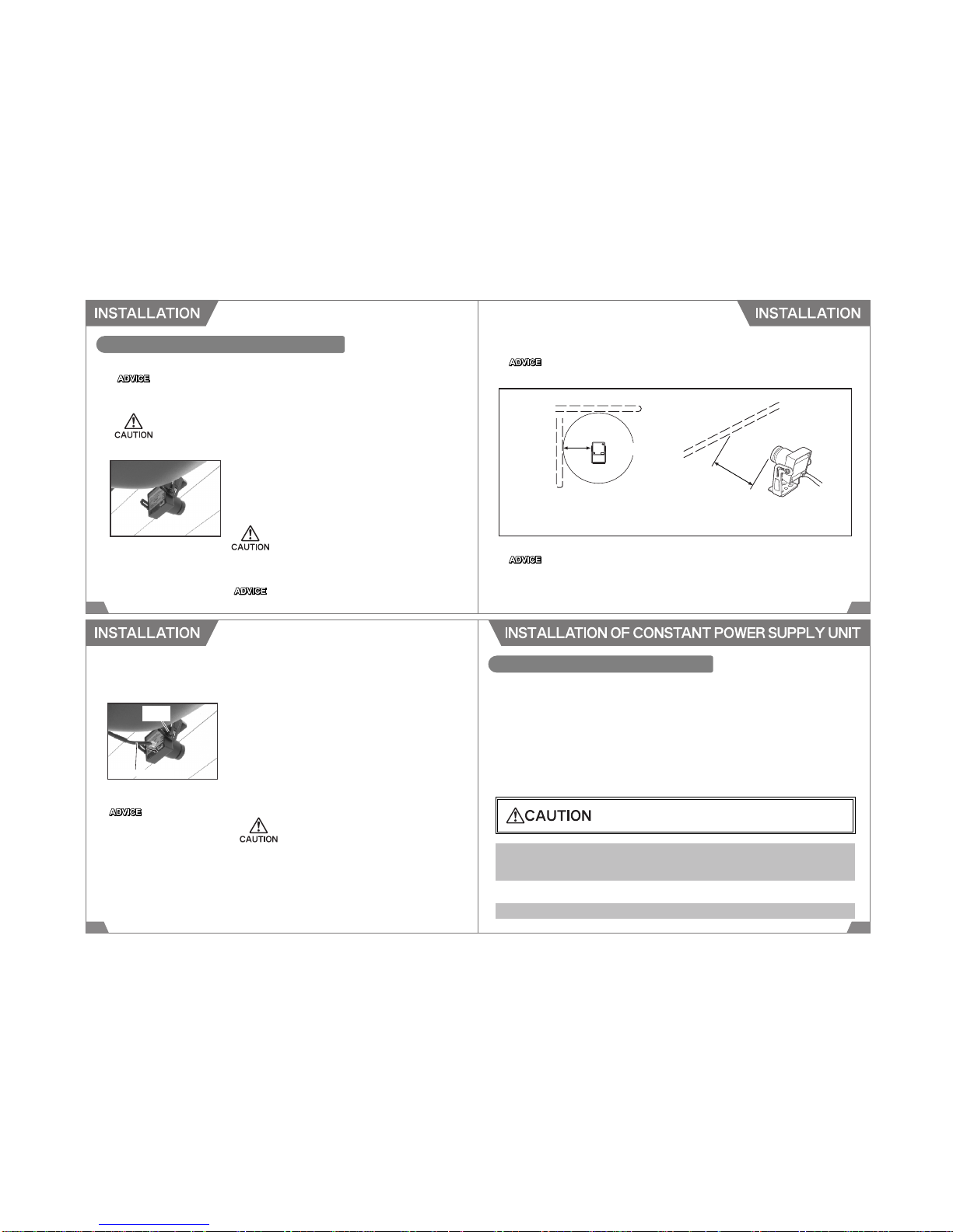
4.Determine the installation position. Make sure the camera lens
face forward, and the unit does not distract driving. Clean the
mounting surface. Affix the provided Fitting Bracket to the wind-
shield using double-side tape.
Install the unit to the position where is within 20% of the
windshield's length from the top edge that is parallel and
vertical to the vehicle's center line (except on the
weatherstrip, moldings, and masking area) or behind the
rearview mirror. (See the diagram below.) Make sure not to
distract driving or the airbag operation. Also, make sure to
install the area where the windshield wipers can reach.)
For vehicles that have mesh-printed portion on the windshield, install
the unit on the extension of the vehicle's center line's left or right.
Within 20%
Within 20%
Parallel and vertical to
the vehicle's center line.
Vehicle's Center Line
If a film antenna for a digital terrestrial or One Seg television is mounted on a front
shield, make sure to maintain at least 10cm distance between the DMR main unit and
film antenna. Failure to do so may cause poor reception.
25 26
<Good Installation>
<Bad Installation>
<Bad Installation>
at least 10cm
DMR
main unit
film antenna film antenna
※ Poor reception may be caused by weak signal and/or reception conditions even
proper distance is maintained between the DMR main unit and film antenna.
Second Camera
Antenna
Antenna
at least 20cm at least
20cm
If a glass antenna for AM radio is mounted on a glass, make sure to maintain at least
20cm distance between the Second camera and the antenna. Failure to do so may
cause poor reception.
Do not use the provided screws(M) to mount the second camera since contact of
a metal part of the camera and screw may cause radio noise.
Second Camera
27 28
INSTALLATION OF SECOND CAMERA
The designated input voltage for the Second Camera is 12V. To install the Second Camera to a
24V vehicle, the Constant Power Supply Unit must be connected.
The Second Camera is not waterproof. Make sure to install the camera where it doesn't get
wet.
5.Determine the installation position. Make sure the camera does
not distract driving. Clean the mounting surface.
Mount the Second Camera using the provided double-sided
tape. Make sure the connector on the back comes downward.
When installing the camera on the windshield, install the
camera to the position where is within 20% of the windshield's
length from the top edge that is parallel and vertical to the
vehicle's center line (except on the weatherstrip, moldings,
and masking area) or behind the rearview mirror. (See the
diagram on page 24.)
The length of the Power / AV Cable to connect the Second
Camera to the DMR main unit is 6.5m.
The DMR main unit can be used without the Second Camera. To use the DMR without the
Second Camera, skip the installation procedure 5 to 8 and go to the procedure 9 on the following
page.
At dark places, such as night, images are recorded in monochrome.
※ Poor reception may be caused by weak signal and/or reception conditions even
proper distance is maintained between the Second camera and the antenna.
Power/AV Cable
Screw
(S)
29 30
11.Secure cables using the provided clips not to distract driving
to prevent possible accident.
7.Connect the Second Camera to the DMR main unit using the
provided Power / AV Cable.
8.Remove the protection cap from the Second Camera.
6.Adjust the angle of the Second Camera. Secure the camera
using the provided small Screw.
9.Plug in the Power Cable to the DMR main unit and the cigar
lighter socket.
10.Start the engine, and make sure the DMR and Second Camera
work properly.
Make sure to maintain adequate
distance between the Constant
Power Supply Unit and antenna
and/or antenna wires of other
electrical devices to prevent poor
reception.
For a 24V vehicle, use the Constant Power Supply Unit
instead of the Power Cable.
Refer to the page 24 for installation.
CONSTANT POWER SUPPLY UNIT
Connecting the Constant Power Supply Unit to the main unit can supply the constant power to the
unit so it can be used as a security camera while the vehicle is parked.
Protection circuit for the car battery is equipped; therefore, this Constant Power Supply Unit can be
used safely without the battery's overload for an extended period of time. The power is automatically
off when the battery voltage falls below 12V (or 24V)more than 3 minutes. When the battery voltage
exceed 12.3V (24.5V), the power supply to the DMR is resumed.
When using this Constant Power Supply Unit, the provided Power Cable cannot be used together.
For a 24V vehicle, always use the Constant Power Supply Unit instead of the Power Cable.
1.When using the DMR as a security camera without starting the engine for an extended
period of time, the car battery may run out depending on conditions of a vehicle and/or
battery or the consumption of current power by other electrical devices.
Make sure to turn off the power of the DMR when a vehicle will be parked more than 3 days.
2.Select the proper input voltage for a vehicle the DMR is installed.
Indicates risk of serious injury or property damage.

31 32
1.Make sure the cable and the Constant Power
Supply Unit are in proper condition for installa-
tion.
3.Disconnect the negative cable form the battery.
4.Select the Input Voltage
Turn off the power of the Constant Power Supply Unit (○side),
and switch the input voltage selection to the side proper for the
vehicle.
Select the proper side of the input voltage.
Connect the black wire from the Constant Power Supply Unit
to a good chassis ground or the ground line.
Find a line of constant 12V (or 24V) power supply using a
tester.
Make sure connectors are properly connected.
INSTALLATION OF CONSTANT POWER SUPPLY UNIT
2.Constant Power Line
5.Connect to Ground Line
7.Mount the Unit
Mount the Constant Power Supply Unit using the provided
Fixture Tape. Make sure to mount to the position where it does
not distract driving using the provided Fixture Tape.
8.Connect to the DMR Main Unit
Connect the Constant Power Supply Unit to the power
connector of the DMR main unit. Turn on the power of the
Constant Power Supply Unit (- side).
9.After Installation
10.Route the cable not to distract driving.
Reconnect the negative cable to the battery. Make sure the
DMR main unit and the Constant Power Supply Unit can be
operated properly.
Connect the red wire from the Constant Power Supply Unit to
the line of constant 12V (or 24V) power supply. Secure the
connected point using a splice or electro tap splice.
6.Connect to Power Supply Line
Make sure to maintain adequate
distance between the Constant
Power Supply Unit and antenna
and/or antenna wires of other
electrical devices to prevent poor
reception.
Input Voltage
Switch
Power Switch
Power Switch
34
OPERATION
33
1.Turn On the Power
2.Start Recording
(1)Make sure the Power Cable is plugged in the DMR main unit properly, and the SD Memory Card
is inserted properly.
(2)Start the engine. The power of the DMR is turned on automatically.
(3)After the power is on, a blue LED and purple LED start blinking, and the unit is started up.
1)Constant Recording Mode
After initialization, recording begins. Recoded data are filed and split into 3 minute blocks. When
a shock/impact is detected during recording, the position is recorded to the G-sensor graph in
the view.
When the unit start-up is completed, the unit beeps 5 times (when warning beeping sound is on.).
When "1Channel" is selected for the Video setting, a red LED comes on. "2Channel" is selected,
a purple LED comes on. During recording, the LED on the left side of the main unit blinks at 1.5
seconds interval. If this LED does not blink, there must be a system error. Turn of the power, and
reboot the unit.
IF the SD memory card is not inserted or write-protected, the unit beeps, and a blue LED and
purple LED blink. Insert a SD memory card, or release the write protection to stop beeping and
blinking.
Under this constant recording mode, a shock or impact can be detected, but the image cannot
be recorded in addition to the image originally recorded.
35 36
2)Shock Sensing Mode
When shock/impact is detected over the preset level, the image can be recorded a set time before
and after. This time can be set as either 10 seconds or 15 seconds under "1Channel" setting
("2Channel" is 10 seconds). Default setting: 10 seconds before and after the impact.
3)Emergency Record
When set in Shock Sensing mode, pushing the button on the DMR will allow events before and
after to be recorded. The time of recording is the same as set in Shock Sensing mode.
5.Ejecting the SD Memory Card
The procedure below must be followed when ejecting the SD memory card to view the recorded
images.
3.Reception of GPS Signal
When the GPS signal is received properly, the GPS LED (Blue)on the right side of the main unit
blinks. It may take a few minutes to several minutes.
4.Stop Recording
Stop driving, and shut off the engine. The recorded images are saved in a few second.
The unit beeps 3 times (When beeping sound is set to on.)and ends recording.
Do not eject the SD memory card before turning off the power of the unit. It may damage the
recorded images.
A.Stop the engine, and remove the ignition key.
B.LED comes off after the unit beeps 3 times (when warning beeping sound is set to on)
to complete recording.
C.Eject the SD memory card after all LED are turned off.
When using the Constant Power Supply unit, make sure the power of the main unit and the
Constant Power Supply Unit are off before ejecting the SD memory card to prevent damage to
the recorded images.
When images were recorded while the GPS wave cannot be received, (especially at beginning)
the file name may not reflect the correct recorded date.
DMR Main Unit
Starting-up
After
Starting-up
During reception of
GPS Signal
In Operation
Detection of
Shock/Impact
Optional
Recording
Microphone
ON
Connection Status
Button Input
LED Status
Left
(Power + Operating Condition)
Right
(GPS) Side
(Microphone)
Beeping
Sound
37 38
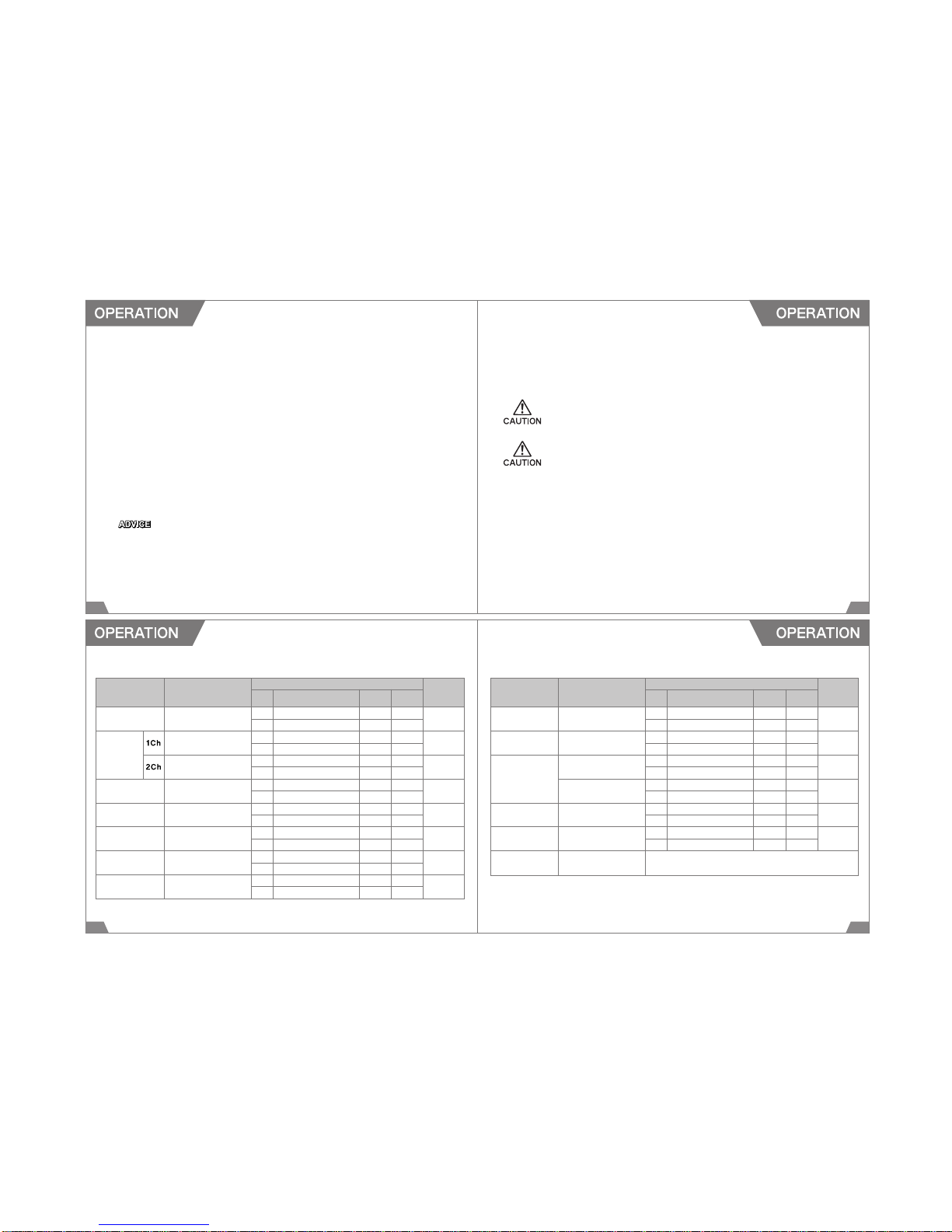
◆LED and Beeping Sound Setting
Power is on.ColorPurpleBlue 5 beeps
Condition
BlinkBlink
(Beep sound is set to on.)
Video settingColor Red Blue
"1Channel"
Condition
OnOff
Video settingColorPurpleBlue
"2Channel"
Condition
OnOff
ColorRed or PurpleBlue
Condition
OnOn
ColorRed or PurpleBlue
Condition
Blink(Every 1.5 sec.)On
ColorRed or PurpleBlue
Condition
Blink(Every 0.3 sec./10 sec.)
On
Press EmergencyColorRed or PurpleBlue
Record Button once.
Condition
Blink(Every 0.3 sec./10 sec.)
On
Press Emergency Record
Color Red
Button more than 2 seconds.
Condition
On
DMR Main Unit
Microphone
OFF
Firmware
Update
Operation End
SD Memory Card
Status
Starting-up
Viewer Mode
Exit from
Viewer Mode
Connection Status
Button Input LED Status
Left
(Power + Operating Condition)
Right
(GPS) Side
(Microphone)
Beeping
Sound
Press Emergency Record
Color Red
Button more than 2 seconds.
Condition
Off
Power is off.ColorRed or PurpleBlue Red 3 beeps
Condition
OffOffOff
(Beep sound is set to on.)
Not insertedColorPurpleBlue
Beep at
Write protect mode
Condition
BlinkBlink
certain intervals
SD Memory Card ErrorColorPurpleBlue 5 beeps
Condition
BlinkBlink
ColorPurpleBlue
2 beeps x 2
Condition
Blink twice
Blink twice
Press Multi ButtonColorBlueBlue 3 beeps
more than 3 seconds.
Condition
OnOn
(Beep sound is set to on.)
Press Emergency Record
Starting-up DMR main unit begins.
Button under Viewer Mode
39 40
OPERATION & FUNCTIONS OF MULTI BUTTON
HOW TO USE THE VIEWER MODE
1.Connecting the AV Cable
(1) Connect the provided AV Cable to the AV OUT Port of the main unit.
(2) Connect the AV Input Cable to the AV Input terminal of the external monitor and the AV Cable
from the main unit.
(3) When the AV Cable is being connected properly, the monitor shows the real-time image from
the main camera. To see the real-time image from the Second Camera, press 「Down」of the
Multi Button to switch the image.
The AV input cable must be equipped with the external monitor. If an AV input cable is not
available, contact the distributor of the external monitor.
If the image was not appeared on the monitor, check "Real-time View Set" under the Viewer
Mode is on.
Button Operation Functions
Real-time Monitoring Playing the recorded imagesSetting Change
Press more than 3 sec.
Starting-up the Viewer Mode
− −
Press (less than 2 sec.) − Execute, Play, StopExecute
Move upward
Image from the main camera.
Move upMove up
Move downward
Image from the second camera.
Move downMove down
Connecting this product to an external monitor equipped with an AV input terminal can play the recorded
images or images in real time on the monitor. Also, setup using a monitor is possible.
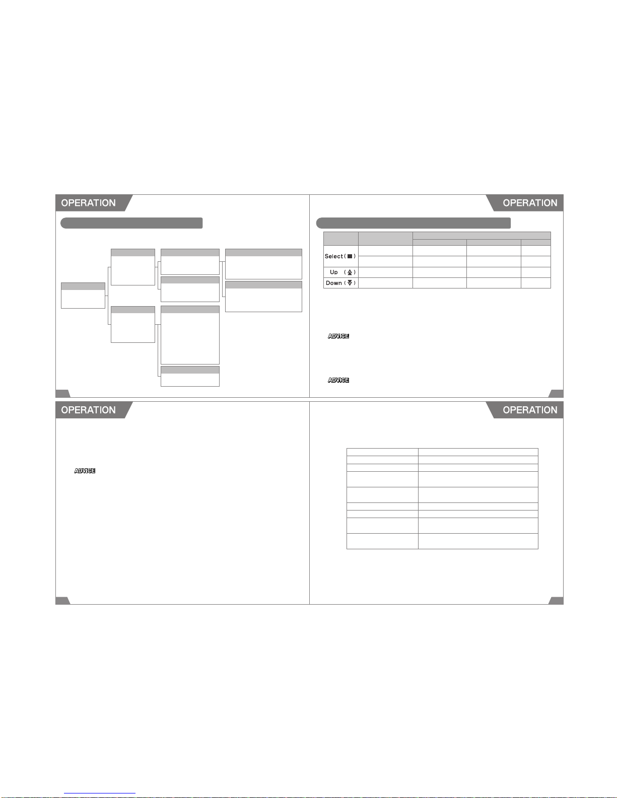
Main Menu
1.Start Recording
2.Recording Files
3.Configuration
Front Recording Files Always Recording Files
1.Previous Menu
2.[CH1]20110407
163156.mp4
3.[CH1]20110407
163456.mp4
4. ・・・
Event Recording Files
1.Previous Menu
2.[EV1]20110417
061158.mp4
3.[EV1]20110417
061527.mp4
4. ・・・
Rear Recording Files
1.Previous Menu
2.Always Recording Files
3.Event Recording Files
Blackbox Configuration
1.Previous Menu
2.Channel Set
3.GMT Set
4.Recording Set
5.G
-
sensor Set
6.Image Sensor Set
7.Image Brightness Set
8.Buzzer Set
9. Real-time View Set
Firmware Version Info
1.Previous Menu
2.Firmware Version
Recording Files
1.Previous Menu
2.Front Recrding
.Files
3.Rear Recording
.Files
Configuration
1.Previous Menu
2.Blackbox
.Configuration
3.
Firmware Version
.Info
1.Previous Menu
2.Always Recording Files
3.Event Recording Files
41 42
5.Closing the Viewer Mode
(1) Return to the menu screen, and select "1.Start Recording" or press the Emergency Recording
Button once to close the Viewer Mode.
(2) When completing the start-up, recording is resumed.
4.Changing DMR Main Unit Settings
(1) Select "3. Configuration" from the main menu.
(2) Select "2. Blackbox Configuration".
(3) When completing each setting, close the Viewer Mode, and restart the DMR main unit.
Without restarting the main unit, setting change(s) will not be executed.
1.Previous Menu To return to the previous screen.
2.Channel Set To select the recording channel.
3.GMT Set To set the GMT. (Set to +9:00 for use in Japan.)
4.Recording SetTo select Constant Recording Mode or
Shock Sensing Mode.
5.G
-
sensor SetTo set the G-sensor sensitivity.
Smaller number is for higher sensitivity.
6.Image Sensor Set To select the main camera's resolution.
7.Image Brightness Set To adjust the image brightness. (1-darkest, 10-brightest)
8.Buzzer SetTo select to buzz when the main unit start-up is
completed.
9. Real-time View SetTo select to show the real-time images on the external
monitor.
2.Starting-up the Viewer Mode
Connect the AV Cable to the external monitor, and press the Multi Button of the main unit more than
3 seconds.
The Viewer Mode starts up after 3 beeps (when beeping sound is set to on.)
Under the Viewer Mode, setting of the main unit and monitoring the recorded images are possible.
3.Playing the Recorded Images
(1) Select "2. Recording Files" from the main screen.
(2) Select "Front Recording Files (Main Camera)" or "Rear Recording Files (Second Camera)".
(3) Select "Always Recording Files (Recorded under Constant Recording Mode)" or "Event
Recording Files (Recorded under Shock Sensing Mode)".
(4) Press the Multi Button to play the images. Under the Viewer Mode, recent 30 files can be
monitored.
(5) Select "1. Previous Menu" to return the previous screen.
Recording of images will be paused under the Viewer Mode. When the Viewer Mode is closed,

4443
Installation of the viewer software to the PC.
With the software, video and information can be shown. Setting of DMR unit can be edited.
The installer program is stored in the included SD Memory card.
The manual is stored in the included SD Memory card.
(File name: DMR ViewerManual_en.pdf)
Please copy the manual to the hard disc of the PC so that it can be referred any time.
Make sure to backup each file to the hard disk of a PC or another memory device before using
this product.
1.Connecting to the PC
Turn off the DMR main unit, and eject the SD memory card from the DMR main unit after all LED go
out, and insert the memory card to the USB card reader connected to the PC.
2.Starting-up the Installer
Double click "DMR_en.msi" file in the SD
memory card.
3.Executing the Installer
Execute the installer and follow the installation
guide.
A USB card reader is not included to this product; it must be prepared separately.
4645
4.Completing Installation
Press "Close" to complete installation.
6.Uninstallation of the Viewer Software
Select 「All Program→DMR→Uninstall DMR」, and start-up the uninstaller.
5.Shortcut of the Viewer Software
The Viewer Software is added to All Programs.
An icon for the shortcut of the Viewer Software
appears on the desktop screen.

47 48
Main Camera1.3M Pixel CMOS Digital Sensor 142.5°
Record 1.3Mega (Input 1280x960, Output 640x480)
Resolutionor VGA (Input 640x480, Output 640x480)
Number of Frame
1 Channel - 1.3Mega: 15 fps / VGA: 30fps
2 Channel - 1.3Mega: 8fps / VGA: 15fps
Video Compression
H.264
Constant Recording Mode: Constantly records in 3 minute segments
Recording Time Shock Sensing Mode: Records 15 seconds before and after an event (total 30 seconds)
The provided 8GB SDHC memory card allows for 16hours 1ch recording.
Impact SensorBuilt-in 3 axes Gravity Sensor
GPSBuilt-in GPS
Storage MediaSD/SDHC memory card (2GB ~ 16GB)
SoundBuilt-in Microphone
BuzzerSet to sound at initialization, firmware update, events, turning the power-off.
LED3 LED (Initialization, Recording, GPS Signal Reception, Microphone On/Off)
Image ViewerViewer Software provided. Recorded images can be played by standard media players.
SizeH:107mm / W:60mm / T:19mm (Attachment not included.)
Weight90g (Attachment not included.)
Power SourceDC12V ~ 24V Negative Ground
Main MaterialPC、ABS
Operating Temperature
-10℃〜60℃
Second Camera 0.27M Pixel Color CCD Sensor 130°(monochrome at dark places)
Power Source DC12V Negative Ground
Operating Temperature
-10℃〜60℃
Power SourceInput: DC12V ~ 24V Negative Ground
Output: DC12V
Main Material PC
Operating Temperature
-10℃〜60℃
Second CameraDMR Main Unit
Constant Power Supply Unit
If this product does not perform properly, check the following items.
If any further assistance is required, please contact your dealer.
◆ The unit does not power on.
○ If the LED (Red/Purple・Blue)do not come on after power is on, make sure the Power Cable is con-
nected properly. Contact your dealer if LED still do not come on even the Power Cable is properly
connected; the SD memory card may be damaged.
○ If the LED (Red/Purple・Blue)comes on dimly, and the DMR does not work, disconnect the power
cable from the DMR main unit, and reconnect the cable after leaving the cable disconnected for 30
minutes.
○12.3V (24.5V)or higher voltage must be applied to operate the Constant Power Supply Unit.
Check the battery voltage.
◆ The DMR does not detect the SD memory card.
○ Turn the power off and eject the SD memory card. Make sure any foreign objects are adhered to
the terminal. Make sure the SD memory card is not write-protected.
Also,
・It takes longer to start activating the unit after power is turned on.
・The unit does not beep at all or beep less than 3 times when deactivating the unit (when warning
・beeping sound is on.).
・The DMR viewer software is shut down when viewing a file or a message "File is broken" appears
・when trying to view a file from the SD memory card on a PC.
When any symptom described above is noticed, format a SD memory card.
Symptoms may be improved.
◆ The GPS signal cannot be received.
○ Reception of the GPS signal may be very poor depending on the area and/or place.
Move the vehicle to the open place, and wait for a few minutes until reception is recovered.
◆ The Viewer Software does not show any map.
○ Make sure the internet connection is setup properly. Also, make sure Internet Explorer is the
version 7.0 or later.
49 50

51
Proper maintenance of this product is necessary in order to maintain the safety, reliability, and function of
this product.
●Maintenance is the responsibility of the driver/owner.
●If work needs to be performed outside the scope of this manual, consult a professional.
●If the vehicle gets damaged, have the repairs performed by a professional.
●If you experience any abnormal noises, scents, or vibrations from the vehicle while driving, reference
the factory service manual.
Names of product, company, etc included in this manual are commonly-used trademarks and/or
registered trademarks. This manual does not show the symbols of Trademark (TM) , Registered
Trademark R , etc.
Table of contents


