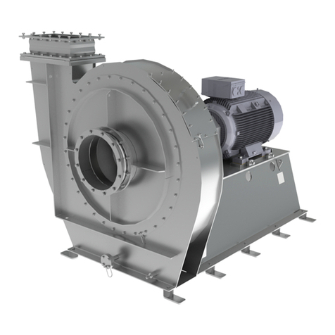
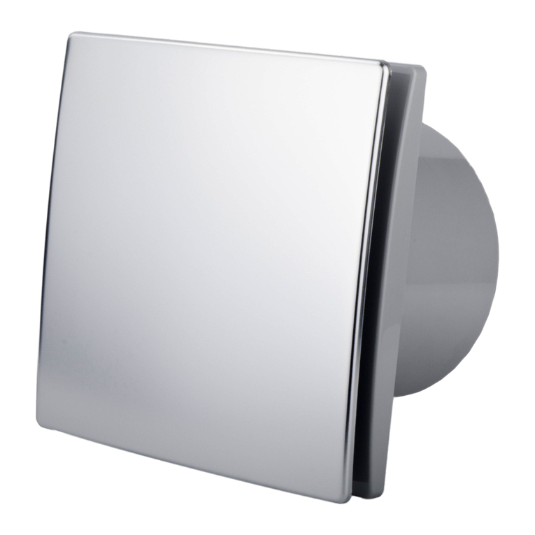
HLU HF R 75-16 D User manual

www.hlu.eu
Operating manual
Small centrifugal fans
HF R 75-16 D
HF R 110-18 D
These operating instructions are valid for the standard and ATEX versions.

2
Operating manual
Small centrifugal fans
HF R 75-16 D | HF R 110-18 D
www.hlu.eu
08.2022
These operating instruction are part of the fan and must be available
to the operating personnel at all times. The safety information given
in these instructions must be followed. In the event of a fan resale,
these operating instructions must be included with the equipment
supplied.
Translation
In the event of supply or subsequent sale into the countries
of the EEA, the operating instructions must be translated into
the language of the user country accordingly.
If the translated text contains divergences, always refer to
the wording of the original (German) operating instructions,
or contact the manufacturer.

Operating manual
Small centrifugal fans
HF R 75 | HF R 110-18 D 3
www.hlu.eu 08.2022
1.1 Index
1. Content
1. Content 3
1.1 Index 3
1.2 EC-/EU-Declaration of Conformity 4
2. Construction and correct use for the intended application 6
2.1 Construction of the fans 6
2.2 Correct use for the intended application and eld of application 7
3. Product specic data 8
3.1 General data 12
3.2 Power supply (see motor type label) 12
4. Safety 13
4.1 Signs and explanations 13
4.2 Fan marking 14
4.3 Built-in safety systems (to be implemented by the user) 15
4.4 Interfaces of the fan 15
4.5 Safety measures (to be implemented by the user) 16
4.6 User‘s responsibilities 16
5. General warning symbols 17
5.1 Hazards 17
5.2 Operating and hazardous areas on the fan 17
5.3 Installation of spare and wear parts 18
6. Installation 19
6.1 Scope of supplies 19
6.2 Transport and packing 19
6.3 Delivery (also with spare and substitute parts) 19
6.4 Intermediate storage 19
6.5 Transport to the place of installation (at the customer‘s site) 20
6.6 Installation, mounting, Initial commissioning 20
6.7 Operating modes 21
7. Operation 21
8. Maintenance / Cleaning 22
8.1 Cleaning 23
8.2 Inspection interval / Function checking 24
8.3 Vibrations 24
8.3 General hints for maintenance 24
8.4 Checks 25
9. Troubles, causes and measures 25
10. Emergency 26
11. Dismantling / Disposal 27

4
Operating manual
Small centrifugal fans
HF R 75-16 D | HF R 110-18 D
www.hlu.eu
08.2022
1.2 EC-/EU-Declaration of Conformity
www.hlu.eu
EC-/EU-
Declaration of Conformity
Page 1of 2Konformitätserklärung_GB
precluding responsibility for components provided or mounted by the customer. If the fan is modied without prior
agreement with HLU, this declaration is void.
Directive / Standard Title
DIN EN ISO 12100:2011 Safety of machinery - General principles for design – Risk assessment and
risk reduction
Reference to the following standards is made additionally in the DIN EN ISO 12100:
DIN EN ISO 13857:2020, DIN EN ISO 14120:2016, DIN EN ISO 13732-1:2008, DIN EN 60204-1:2019
DIN ISO 21940-11:2017 Procedures and tolerances for rotors with rigid behaviour
DIN EN IEC 61000-6-4:2020 Electromagnetic compatibility, Generic standards - Immunity for industrial en-
vironments
DIN EN IEC 61000-6-2:2019 Electromagnetic compatibility, Generic standards; Emission standard for indus-
trial environments
VDMA 24167:1994 Fans - Safety requirements
For the purpose of
J EC Machine Directive 2006/42/EC, Annex II A for Machines
J EC Low Voltage Directive 2014/35/EU, Annex III
J EMC Directive 2014/30/EU, Annex I and II
We hereby declare that the construction type of the supplied version of:
HF R …, HF D …, HF A …, AX 58 …, RV …, MRV …, SDR …
Manufacturer: Hürner Luft- und Umwelttechnik GmbH
Ernst-Hürner-Straße
35325 Mücke-Atzenhain
Germany
in the delivered version, as a separate component within an installation, complies with the above regulations and
the following standards or normative documents:
Name and address of the persons, who are authorized, to assort the technical documents:
J Anne-Christin Vögl-Schmitt, Hürner Luft- und Umwelttechnik GmbH, Ernst-Hürner-Straße,
35325 Mücke-Atzenhain, Germany

Operating manual
Small centrifugal fans
HF R 75 | HF R 110-18 D 5
www.hlu.eu 08.2022
www.hlu.eu
EC-/EU-
Declaration of Conformity
Page 2of 2Konformitätserklärung_GB
Name and address of the persons, who are authorized, to assort the technical documents:
J Anne-Christin Vögl-Schmitt, Hürner Luft- und Umwelttechnik GmbH, Ernst-Hürner-Straße,
35325 Mücke-Atzenhain, Germany
precluding responsibility for components provided or mounted by the customer. If the fan is modied without prior
agreement with HLU, this declaration is void.
Directive / Standard Title
DIN EN 1127-1:2019 Explosion prevention and protection - Part 1: Basic concepts and
methodology
DIN EN 13237:2013 Terms and denitions for equipment and protective systems intended for
use in potentially explosive atmospheres
DIN EN 14986:2017 Design of fans working in potentially explosive atmospheres
DIN EN 15198:2007 Methodology for the risk assessment of non-electrical equipment and compo-
nents for intended use in potentially explosive atmospheres
DIN EN ISO 80079-36:2016 Part 36: Basic method and requirements
DIN EN ISO 80079-37:2016 Part 37: Protection by constructional safety „c“
For the purpose of
J EC Directive 2014/34/EU (ATEX) concerning equipment and protective systems
intended for use in potentially explosive atmospheres
We hereby declare that the construction type of the supplied version of:
HF R …, HF D …, HF A … PTB 03 ATEX D089 + 557/Ex-Ab 3466/21
RV …, MRV … PTB 04 ATEX D097
SDR … PTB 04 ATEX D098
AX 58 … PTB 04 ATEX D099
Manufacturer: Hürner Luft- und Umwelttechnik GmbH
Ernst-Hürner-Straße
35325 Mücke-Atzenhain
Germany
conrm in exclusive responsibility to produce solely in combination with the ATEX-name plate and the
individual test report 2.2 according DIN EN 10204:2004 in the delivered version, as a separate component
within an installation, complies with the standards / regulations of the general declaration of conformity, the
above regulations and the following standards or normative documents:

6
Operating manual
Small centrifugal fans
HF R 75-16 D | HF R 110-18 D
2. Construction and correct use for the intended application
www.hlu.eu
08.2022
2.1 Construction of the fans
Housing with inlet and
outlet adapter
Motor
Terminal box
Frame
Fig. 1a| Overview of the fan HF R 75-16 D and HF R 110-18 D
consist of the following main assemblies: Fan base frame, housing, impeller and drive motor.
The HF R 75-16 D fan is also built without base frame, but with a ange for mounting on a wall
or ceiling on the inlet side. The housings and impellers are manufactured by injection moulding.
The fan housings are made of ame-retardant polypropylene (PPs / PP-FR) according to UL
49V0 or ame retarding and electrical-conductive (PPs-el / PP-FR-el). Due to the low kinetic
energy, splinter protection is not required; the housing provides sucient protection. The impel-
ler of the HF R 75-16 D series and the impeller of the HF R 110-18 D are made of PP-el. The
impellers rotate counterclockwisely and are equipped with small back blades. The housing shaft
passage is tted with a sealing ring. Outdoor and indoor installation is possible. For outdoor
installation, motor covers are available.
The impellers of these assemblies are positively bonded to the motor shaft. In the event of a
repair, the complete fan must be replaced.
The exhaust uid is aspirated axially by the rotating impeller and transported radially to the
outlet in the helicoidal housing. The applied energy is converted into mass ow and pressure
increase of the exhaust uid in the impeller.

Operating manual
Small centrifugal fans
HF R 75 | HF R 110-18 D 7
www.hlu.eu 08.2022
Installation inside the explosion-hazarded area:
Installation inside the explosion-hazarded area is not permissible,
unless the fan is provided explicitly for this purpose (see type label
Chapter 4.2).
If the fan for an installation with an open inlet or outlet or is provided
for an inlet-side duct connection as part of a larger installation, the
operator is obligated to prevent the penetration of foreign bodies that
can cause ignition according to DIN EN 14 986, point 4.22.
Repair and maintenance works of explosion-proof fans may only be
performed by qualied persons in the explosion protection by
using original spare parts.
If the fan has an open inlet and / or outlet (Type A, B, C according to
ISO 13349), the fan must have the same category inside and outside.
Types of connection
2.2 Correct use for the intended application and eld of application
The fans are suitable for exhausting aggressive, dust-free, low-aerosol gases and clean air.
Explosive atmosphere can be exhausted only using fans designed specially for this application.
The permissible gas temperatures for the most frequently used plastics materials are generally
with PE, PE-FR (PEs) -20 °C to 60 °C,
with PP, PP-FR (PPs): 0 °C to 70 °C,
These temperatures must not be exceeded.
Depending on gas composition and impeller speed, these temperature ranges must be check
and restricted, if necessary. With particularly aggressive media, the reductions must be checked
and determined individually in each case. The max. ambient temperature is 40 °C.
Sucient cooling can be ensured regardless of the volume ow, in accordance with the
above-mentioned conditions.
The fan was developed, designed and built exclusively for industrial and commercial use. Using
the fan for domestic purposes is excluded.
Residual risks
Although the fans have been constructed according to the newest
technology as well as to the security rules and they are monitored by
quality assurance (QA) system, there remains a residual risk due to
the possible rupture of the impeller. This happens especially, when
the conditions of use have not been complied. Therefore it is neces-
sary to pay attention on technically perfect conditions and on the right
case of application. The environment of the fans has to be secured
in such a way, that in case of a damage, neither persons nor objects
get harmed.

8
Operating manual
Small centrifugal fans
HF R 75-16 D | HF R 110-18 D
www.hlu.eu
08.2022
These assemblies are intended exclusively for the above purpose.
Using the assemblies for dierent purposes than described above,
or modifying them without written consent of the manufacturer are
considered as non-compliant with the intended application. The ma-
nufacturer cannot be held responsible for damage resulting from such
use. The risk is borne exclusively by the user. The fan may be started
only after checking that all safety devices are operable and that the
system in which this fan is installed complies with the EU directives.
The correct use for the intended application also implies compliance with the instructions given
in the manufacturer operating manual and with the conditions for maintenance and repair.
The plastic fans are not covered by the „Regulation No 327/2011 of the European Commission
about the implementation of Directive 2009/125/EC (ErP Directive)“ because they are intended
for the extraction of highly corrosive media.
The materials/uids for the correct use of the fan in compliance with
the intended application are procured and applied by the manufactu-
rer. The user is responsible exclusively for correct handling of these
materials/uids and the related hazards. Information on hazards and
disposal must be provided by the user. Follow the rules given in the
manufacturer‘s safety data sheets for materials and uids.
3. Product specic data

Operating manual
Small centrifugal fans
HF R 75 | HF R 110-18 D 9
www.hlu.eu 08.2022
Dimensions and design can be changed | Dimensions in mm
Technical data sheet HF R 75-16 D
Fig. 2a| Frame design with WS- or DS-Motor
Fig. 2b| Frame design with DS-Ex-Motor
Capacitor only
at WS version

10
Operating manual
Small centrifugal fans
HF R 75-16 D | HF R 110-18 D
www.hlu.eu
08.2022
Dimensions and design can be changed | Dimensions in mm
Technical data sheet HF R 110-18 D
Fig. 2c| Frame design with WS-Ex-Motor
Fig. 2d| Frame design with WS- or DS-Motor
Capacitor only
at WS version

Operating manual
Small centrifugal fans
HF R 75 | HF R 110-18 D 11
www.hlu.eu 08.2022
Dimensions and design can be changed | Dimensions in mm
Fig. 2e| Frame design with DS-Ex-Motor (PPs for Zone 2 | PPs-el for Zone 1)
Fig. 2f| Frame design with WS-Ex-Motor (PPs for Zone 2 | PPs-el for Zone 1)

12
Operating manual
Small centrifugal fans
HF R 75-16 D | HF R 110-18 D
www.hlu.eu
08.2022
3.1 General data
Ambient temperature range
The specications on the type label are applicable. If they are missing, the temperature range
is - 20 °C to + 40 °C.
Noise level
For the value applicable to each fan, see the manufacturer internet site, or contact us via phone.
3.2 Power supply (see motor type label)
Optionally, the electric motors can be controlled continuously by means of a frequency inverter.
The maximal rotation speed at the impeller (see fan type label) must not be exceeded.
The ICA (instrumentation technology, control technology, automation technology) on site must
ensure protection against overspeed in compliance with EN 60204-1 and compliance with the
technical standard against electrical erosion. The instructions of the frequency-converter and
motor manufacturers must be observed.
Motor bearing damage caused by inadequate measures during operation on frequency inver-
ters does not constitute cause for complaint.
We explicitly state that, if the bearing damage is demonstrably caused by bearing currents, HLU
or the motor manufacturer is not at fault. A bearing that has failed due to bearing currents is not
a fault that is due to a manufacturer’s error (production error).
In case of operation of several motors with a frequency inverter all-pole sinusoidal lters should
be used between frequency inverter and motor.
If frequency inverters are used in the explosion-hazarded area (Zone 1) these must be installed
outside the explosion-hazarded area and ameproof motors to DIN EN 60079-1 must be used.
Others
More relevant data are given on the type label.
Before connecting the fan, check the specications on the type label
and dimension the electrical control system accordingly.

Operating manual
Small centrifugal fans
HF R 75 | HF R 110-18 D 13
www.hlu.eu 08.2022
4.1 Signs and explanations
Warnings
are marked with a „STOP“ sign.
The information given in the operating manual is binding
is marked with a „book“.
4. Safety
Danger warnings
are marked with a warning triangle.
Hazards due to explosive atmosphere
are marked with the symbol shown opposite.
Notes
are marked with a hand symbol.
Hazards due to electric current
are marked with the symbol shown opposite.
Protective earth connection
is marked by these symbols at the connecting points.

14
Operating manual
Small centrifugal fans
HF R 75-16 D | HF R 110-18 D
www.hlu.eu
08.2022
4.2 Fan marking
Fig. 3a| Type label (normal application)
Fig. 3b| Type label (explosive atmosphere)
Specications for fans without explosion protection:
Type
Order no. (AB) Construction year
Fan-specic data
Specications for fans with explosion protection:
Type Denomination of explosion
protection type
Ex-Zone Temperature
Motor explosion protection type
Order no. (AB) Construction year
Fan-specic data
Caution
Fans without explosion protection marking are not permissible for
operation inside the explosion-hazarded atmosphere.
This applies to the environment and the exhausted uid.
Meaning of possible device categories on the type label:
II 2G The fan is suitable for exhaustion from zone 1
and for installation in zone 1
II 2/3G The fan is suitable for exhaustion from zone 1
and for installation in zone 2
II 3G The fan is suitable for exhaustion from zone 2
and for installation in zone 2
II 3/-G The fan is suitable for exhaustion from zone 2
and must be installed outside the hazardous area
The information given in these operating instructions is only applicable to the fan type specied
on the title page. The type label with the type denomination is located on the base frame or on
the side panel of the fan housing. With all enquiries, make sure to specify the order conrmation
no. and the type label properly to ensure correct and quick handling.

Operating manual
Small centrifugal fans
HF R 75 | HF R 110-18 D 15
www.hlu.eu 08.2022
4.3 Built-in safety systems (to be implemented by the user)
The built-in safety devices must be checked at regular intervals:
d = daily, w= weekly, m= monthly, j = yearly.
The following methods must be used for checking:
V= visual check, F= functional check, M = measurement.
Overcurrent protection device
To prevent overheating (re hazard) in the event of overload (e.g. due
to clogging), the fan drive has to be provided with an overcurrent pro-
tection device.
Thermal contact (optional)
For temperature monitoring, the fan is equipped with a thermal
contact. In the event of a temperature increase, the motor switches
o.
PTC resistor (optional)
Don‘t connect the PTC resistor to the mains voltage. Avoid exceeding
a max. PTC resistor test voltage of 2.5 V.
Protective claddings
All mobile fan components driven by the electric motor as well as all
other hazardous parts of the fan are covered by xed, safely fastened
protective claddings that can be removed only using tools.
Check
Interval Method
y F
Check
Interval Method
y F
Check
Interval Method
y F
Check
Interval Method
m V
Deactivating the safety devices, or changing their operating principle,
is strictly prohibited.
4.4 Interfaces of the fan
Electrical connection
The electrical connections are made using a 4-wire supply cable sys-
tem, 3 phases and 1 earth conductor with three-phase motors and
using a 3-wire supply cable system, 1 phase, 1 neutral wire and 1
earth conductor with alternating current motors.
Check
Interval Method
yV, F, M
The fan has the following interfaces:
J Outlet side (connection via sleeve with tightening strap)
J Terminal box or maintenance switch (electric supply)
J Inlet side (connection via sleeve with tightening strap)

16
Operating manual
Small centrifugal fans
HF R 75-16 D | HF R 110-18 D
www.hlu.eu
08.2022
4.5 Safety measures (to be implemented by the user)
We point out that the user is under the duty to:
J instruct the operating and maintenance personnel on the protective devices of the fan,
J and to ensure supervision concerning compliance with the safety measures.
This operating manual must be kept for future use. The specied frequency of inspection and
control measures must be met.
J The chapters related to transport, installation and mounting, maintenance, troubles/causes/
troubleshooting must be understood by a qualied person. Work described in this chapter
may be performed only by qualied personnel.
4.6 User‘s responsibilities
In the European Economic Area, compliance with Council Directive
(89/391/EEC) and the related individual directives, especially Council
Directive 89/655/EEC Concerning the Minimum Safety and Health
Requirements for the Use of Work Equipment by Workers at Work in
the relevant national version is mandatory.
The user must obtain the local operating licence and follow the relevant rules.
Additionally, the user must ensure compliance with the national legal regulations concerning
J the personnel safety (regulations relating to accident prevention)
J the safety of work equipment (protective equipment and maintenance)
J product recycling (Waste Management Law)
J material disposal (Waste Management Law)
J cleaning (cleaning agents and disposal)
J and comply with the requirements for environment protection.
To avoid the occurrence of ignition sources, the operating and main-
tenance personnel must be equipped properly and receive adequate
instructions for realization of cleaning and maintenance work, e.g.
J to avoid the use of tools giving rise to sparking,
J strict observance of the smoking ban,
J to avoid the actuation of ignition sources (e.g. lighters, etc.).

Operating manual
Small centrifugal fans
HF R 75 | HF R 110-18 D 17
www.hlu.eu 08.2022
5.1 Hazards
Pay attention to the safety devices described in this manual and follow the safety notes.
During setup, maintenance and repair work, mind the squeezing
hazards.
During setup, maintenance and repair work, mind the hazard due to
electric current!
During setup, maintenance and repair work, be aware of the risk of
getting burned due to hot components.
In the event of a failure of the forced ventilation, the drive motor pre-
sents a hazard of getting burned.
5. General warning symbols
When doing setup, maintenance and repair work within the ex-
plosion-hazarded area, make sure that there isn‘t a critical gas
concentration. Use a gas detector. Always avoid handling all kinds of
ignition sources inside the explosion-hazarded area. Welding, cutting
and polishing work may be performed only, if the related permission
was granted.
5.2 Operating and hazardous areas on the fan
Hazardous area
During setup, maintenance and repair work, the overall area around the fan is a hazardous
area.
During maintenance and repair work, the hazardous area extends 1 m
around the fan. The ap pivoting area must be taken into account as
well. Keep the area around the fan free from any objects.

18
Operating manual
Small centrifugal fans
HF R 75-16 D | HF R 110-18 D
www.hlu.eu
08.2022
5.3 Installation of spare and wear parts
Hürner Luft- und Umwelttechnik
Ernst-Hürner-Straße
35325 Mücke-Atzenhain
Germany
Tel.
Fax
E-Mail
+49 6401 9180 - 0
+49 6401 9180 - 142
www.hlu.eu
Sälzerstraße 20a
56235 Ransbach-Baumbach
Germany
Tel.
Fax
+49 2623 92 95 9 - 0
+49 2623 92 95 9 - 99
We point out explicitly that spare parts and accessories not supplied by us are not checked and
released for use by us either. Installation and/or use of these products can change the design
properties of your fan negatively.
The manufacturer cannot be held responsible for damage resulting from the use of other than
original components. In connection with the order conrmation, you will receive a data card and
a spare parts list for the fan.
If you need spare parts, please, inform our sales partner:
For Asien: Hürner Funken Malaysia Sdn. Bhd.
Lot 3, Milon Industrial Park
Jalan Minlon Utama o Jalan Taming 2
Taming Jaya, 43300 Balakong
Selangor DE
Malaysia
Tel.
Fax
+ 603 8961 9863
+ 603 8961 9862
www.huerner-funken.com.my
When ordering spare parts, please specify the following data:
J Order no. (see type label)
J Fan type
J Spare part denomination

Operating manual
Small centrifugal fans
HF R 75 | HF R 110-18 D 19
www.hlu.eu 08.2022
6.1 Scope of supplies
6.2 Transport and packing
Although the fans are checked and packed carefully before shipment, damage during transport
cannot be excluded.
6. Installation
6.3 Delivery (also with spare and substitute parts)
Inspection of incoming components:
J Check, if the consignment is complete according to the bill of delivery.
In the event of damage
J Check the consignment for damage (visual inspection).
In the event of complaints
If the consignment was damaged during transport:
J Contact the last forwarder immediately.
J Keep the packaging (for checking by the forwarder or for returning the product).
Packaging for returning the product
J If possible, use the original packaging and the original packaging material. If the original
packaging and packaging material haven‘t been kept, use commercial packaging material.
Fasten the fan to a transport pallet (it must be dimensioned appropriately for the weight).
J With any questions relating to packaging and safe transport, please, consult the manufac-
turer.
6.4 Intermediate storage
The equipment delivered to the user comprises:
J Small centrifugal fan
J Operating manual
J Technical documents
For the detailed scope of equipment supplied, refer to the order conrmation.
The fans should be stored in a room or under a shelter. With outdoor storage, protect the
fan from dirt and atmospheric conditions using a canvas cover. Keep the storage temperature
between 0 °C and + 40 °C.

20
Operating manual
Small centrifugal fans
HF R 75-16 D | HF R 110-18 D
www.hlu.eu
08.2022
6.5 Transport to the place of installation (at the customer‘s site)
Transport must be performed only by qualied personnel in complian-
ce with the local conditions and any warning notes on the packaging
material.
The fan or fan unit is transported on transport pallets to the site.
The fan may be connected to the supply voltage and switched on
only, when the pipe (on the inlet and outlet side) has been connected
completely.
Installation must be performed according to the connecting diagram in
the motor operating instructions only by adequately trained and qua-
lied personnel.
6.6 Installation, mounting, Initial commissioning
Installation, mounting and initial commissioning of the fan are performed by qualied personnel
of manufacturer or by qualied customer personnel that must have been trained adequately for
this work.
J The constructional arrangement of the fan must ensure that operational underpressure con-
ditions are present at the shaft passage.
J The installation of the fans and their components are based on the on-site installation plan.
J The fan must be mounted on vibration dampers screwed to the pre-drilled points in the base
frame and anchored in the on-site foundation. This is necessary to absorb any vibrations
that occur and to prevent damage to the drive and fan.
J The fan must not be operated in non-installed condition. The impeller must be free to move
without any impediment at all times.
J Mount the (on-site) pipe.
J The fan is equipped with a terminal box (or maintenance switch) for connecting to the mains
supply. The motor enclosure must be closed using a sealing joint certied according to the
EN IEC 60079-0 and EN IEC 60079-1 standards. Users will have to connect the cable
terminals using one of the protection types specied in standard EN 60079-0. The energy
supply can be cut o using an onsite maintenance switch (if it is not already installed at the
fan).
J Check before the rst operation that the turning direction is correct (direction arrow on the
fan housing) and that the max. speed is not exceeded (see nameplate).
J If there is danger of foreign parts falling into the fan or being aspirated, the connected pipe
upstream and downstream of the fan must be provided with a protective grid (min. IP20 to
EN 60529).
J The inside of the fan and of upstream and downstream channels and units must be kept
free from foreign bodies.
J See point 3.2
J Ensure that connected lines do not carry loads which lead to a distortion of the fan housing.
This manual suits for next models
1
Table of contents
Other HLU Fan manuals
Popular Fan manuals by other brands
Flex-a-Lite
Flex-a-Lite 40 installation instructions

TEFAL
TEFAL VU256 Series user guide

DuraVent
DuraVent PelletVent UL 641 installation instructions

Solatube
Solatube Bathroom Ventilation Kit Product installation guide
Hunter
Hunter 25511 owner's guide
Vent-Axia
Vent-Axia Lo-Carbon PoziDry Compact Series Installation and wiring instructions

OSTBERG
OSTBERG SAU EC Series Assembly/installation instructions

Vectaire
Vectaire eSmile Installation and operating instruction

Canarm
Canarm DELHI 300 Series Operation instructions and parts manual
ECRON
ECRON RD40 AC user manual

Ruck Ventilatoren
Ruck Ventilatoren KVT 20 Series Assembly instruction
aldes
aldes VS4 MAX instructions
