manuals.online logo
Brands
  1. Home
  2. •
  3. Brands
  4. •
  5. Solatube
  6. •
  7. Fan
  8. •
  9. Solatube Bathroom Ventilation Kit User manual

Solatube Bathroom Ventilation Kit User manual

Bathroom Ventilation Kit
Product Installation Guide
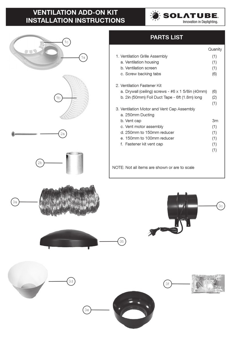
Parts List
Ventilation grille
assembly
Ventilation housing
6 x Screw backing tabs
Ventilation screen
100mm in-line fan motor assembly
Single phase induction motor
Spring operated, non-return
flap to prevent backdraughts
Mounting bracket
Ducting (two x 3 metre lengths)
Soffit/fascia external exit vent
Integral timer
Please note and understand the following before beginning
installation:
Pull switch
6A 2-way ceiling switch, can also be
wired as 1-way (BS EN 60669-1)
Read through this installation guide and the separate
instructions provided with the fan motor. If you have any
questions, please contact the supplier before commencing
installation.
The Solatube Bathroom Ventilation Add on Kit is intended for
use solely as a component of Solatube Daylighting Systems
and should be used only in the manner intended by the
manufacturer.
This unit is for general ventilating use only in bathrooms, toilets,
shower rooms and utility rooms. It is not suitable for use in
kitchens.
Electrical wiring must be carried out by suitably qualified
persons, and in accordance with all applicable codes and
standards, including fire-rated construction. Solalighting Limited
(seller) assumes no responsibility or obligation whatsoever for
the failure of an architect, contractor, installer, or building owner
to comply with all applicable laws, ordinances, building codes,
electrical codes, energy codes, fire and safety codes and
requirements, roof warranties and adequate safety precautions.
Before installing or servicing the unit, switch off power at the
consumer unit and take measures to prevent power from being
switched accidentally, eg lock it or securely fasten a prominent
warning label to the consumer unit to indicate it must not be
switched on.
Exhaust fans must always be vented to the outdoors.
If this unit is to be installed over a bath or shower, the circuit
must be marked as appropriate for the application and be
connected to a circuit breaker or trip switch and comply to
current IEE regulations.
Never place a switch where it can be reached from a bath or
shower.
Do not use this fan with any solid-state speed control device.
This guide is for installing the Solatube
Bathroom Ventilation Kit as an add-on to the
Solatube 160 DS Daylighting System (250 mm
diameter). The optional Solatube Electric Light
Add-on Kit may also be installed with the
Solatube Bathroom Ventilation Kit. Please refer
to the installation guide for the Solatube
Brighten Up Series, and, if using, the Solatube
Electric Light Add-on Kit installation guide to
complete your installation.

Options (included only if specified)
Universal pitched roof-
mounted exit vent
Solatube Electric Light
Add-on Kit
ML-INST-BVK14
Motor assembly specification
Fan motor assembly:
100 mm in-line
Max operating temperature:
40°C
Motor:
Powerful, yet quiet unobtrusive single phase
induction motor with backward curved
centrifugal impellers for a large airflow
providing a long maintenance-free life
Moisture:
Suitable for a wide range of applications
including bathrooms, toilets, shower
rooms and utility rooms.
Not suitable for kitchens.
Supply:
220-240V –AC 50Hz
Fan Speed:
1400 rpm
Airflow:
Extract rates of 110m³/hr / 31 litres per second
Maximum pressure:
120 Pa
Compliance:
Designed to comply with the 2006 Building
Regulations on Ventilation (F1) CE label
Flexible duct:
Local Building Codes may require air
duct (class 0) for certain fire-rated
installations
Step 1 –marking location for the fan motor assembly
Refer to the Solatube Brighten Up Series installation guide to
mark the ceiling and roof location of the Solatube 160 DS
Daylighting System.
In the roof void, locate a mounting location that allows the fan to
be installed horizontally. Check that wiring can be run to the
planned location and that the ducting supplied can reach this
location from the roof exit and ceiling location respectively,
allowing for a u-bend in the duct to act as a condensation trap.
Refer to the installation instructions supplied with the fan motor
assembly (diagram A).
Diagram A
Step 2 –mark the location for the ventilation housing
Using the grille assembly as a guide, make a template from card
(you could use the Solatube packaging), ensuring you cut the
template 20mm smaller than the outer edge of the grille assembly.
Place the template on the ceiling surface within the roof void,
ensuring it aligns with your ceiling marker and draw a line around
the template (diagram B).
Diagram B
Step 3 –install the ventilation housing
Cut along the line and remove the ceiling material. Remove the
screw backing tabs from the ventilation housing. Secure the
ventilation housing with six No.6 (40mm) drywall (ceiling) screws
and the six screw backing tabs (diagram C).
NOTE: For an air infiltration seal, apply a 5mm bead of sealant to
the back of the ventilation housing prior to installation.
Diagram C
Step 4 –install the fan motor assembly & switch
Please refer to the separate installation guide enclosed for mounting and wiring the motor assembly and switch. Ensure
the fan motor is mounted horizontally.
Step 5 –connect the ducting
Run the air duct from the 100mm diameter upstand spigot to the
inlet of the fan motor assembly. On the exhaust side of the fan
motor assembly, run the air duct to the fascia/soffit exit vent or
optional roof vent (see separate installation guide provided with
optional roof vent).
For best venting performance, make the air duct run as short as
possible with minimum bends, cutting the duct as necessary.
Ensuring an overlap of at least 25mm, secure the duct at each
connection using the zip ties supplied and then cover with duct
tape to create a seal (diagram D).
Diagram D
Joists
Select a mounting location that allows
the fan motor to be installed horizontally
Step 6 –fit the ventilation screen
Align the Ventilation screen with the Ventilation housing and snap
into place by pushing gently upwards (diagram E).
Diagram E
Step 7 –fit the Effects lens and ceiling fitting
Insert the Effects lens straight up into the bottom tube assembly
until it sits into the recess at the base of the bottom tube
assembly, with the clear plastic tab pointing downwards. Then
place the ceiling fitting up into the lower edge of the bottom tube
assembly, aligning the male and female lugs, and twist to secure
in place (diagram F).
You have now completed installation of your Solatube
Bathroom Ventilation Kit.
Diagram F
If you have any questions regarding the installation of your
Solatube Bathroom Ventilation kit please contact us –we shall be delighted to help.
Effects lens
Ceiling fitting
Solatube Scotland
Tel: 01721 730385 | Email: [email protected]

Other Solatube Fan manuals

Solatube Brighten Up 160 DS User manual

Solatube

Solatube Brighten Up 160 DS User manual

Solatube RV-57 User manual

Solatube

Solatube RV-57 User manual

Solatube Solar Star RM 1500 User manual

Solatube

Solatube Solar Star RM 1500 User manual

Solatube VENTILATION ADD-ON KIT User manual

Solatube

Solatube VENTILATION ADD-ON KIT User manual

Solatube WHF 1500 User manual

Solatube

Solatube WHF 1500 User manual

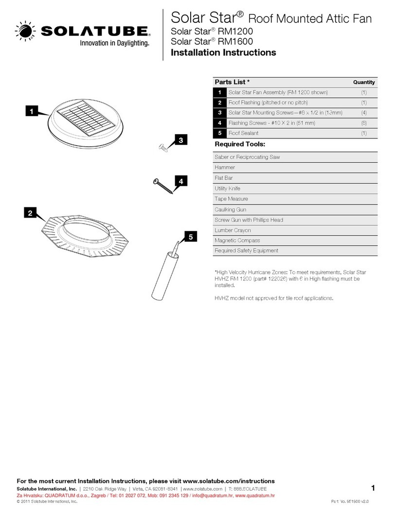
Solatube Solar Star RM1200 User manual

Solatube

Solatube Solar Star RM1200 User manual

Popular Fan manuals by other brands

Hunter 23722 Owners and installation manual

Hunter

Hunter 23722 Owners and installation manual

kookaburra 519245 Assembly & care instructions

kookaburra

kookaburra 519245 Assembly & care instructions

Emerson Anderson Greenwood 2000A Series instruction manual

Emerson

Emerson Anderson Greenwood 2000A Series instruction manual

Vents-us LD 100 installation guide

Vents-us

Vents-us LD 100 installation guide

Hunter 28439 Owner's guide and installation manual

Hunter

Hunter 28439 Owner's guide and installation manual

Monte Carlo Fan Company 5LD52 Series Owner's guide and installation manual

Monte Carlo Fan Company

Monte Carlo Fan Company 5LD52 Series Owner's guide and installation manual

Impecca FANFAIR FWF-1600 user guide

Impecca

Impecca FANFAIR FWF-1600 user guide

nystrom SVT Installation, operation & maintenance manual

nystrom

nystrom SVT Installation, operation & maintenance manual

Carro CES563FL installation guide

Carro

Carro CES563FL installation guide

Lasko U15610 operating manual

Lasko

Lasko U15610 operating manual

Mitsubishi Electric CITY MULTI PDFY Series Technical & service manual

Mitsubishi Electric

Mitsubishi Electric CITY MULTI PDFY Series Technical & service manual

Standler Form Q operating instructions

Standler Form

Standler Form Q operating instructions

Hunter TABLE FAN owner's guide

Hunter

Hunter TABLE FAN owner's guide

Sealey SWF16WR.V5 manual

Sealey

Sealey SWF16WR.V5 manual

Maico ECA 15/2 E Mounting & operating instructions

Maico

Maico ECA 15/2 E Mounting & operating instructions

Rowenta Silent Comfort 3-in-1 HQ812 Series user guide

Rowenta

Rowenta Silent Comfort 3-in-1 HQ812 Series user guide

Brentwood Kool Zone F-9DW Operating and safety instructions

Brentwood

Brentwood Kool Zone F-9DW Operating and safety instructions

Dioluce DL-R24-4530-5K0-001 installation instructions

Dioluce

Dioluce DL-R24-4530-5K0-001 installation instructions

manuals.online logo
manuals.online logoBrands
  • About & Mission
  • Contact us
  • Privacy Policy
  • Terms and Conditions

Copyright 2025 Manuals.Online. All Rights Reserved.