HM Bike DHM User manual


The Bycicle and its components
Handlebars1
Stem2
Bell3
Headset4
Headlight5
Mudguard6
Fork7
Front brake8
Tires9
Wheels10
Bottom bracket11
Pedals12
Chain13
Rear derailleur14
Rear light15
Reector16
Rack17
Seat18
Frame19

Contents
3
Congratulations on your new DHM bicycle!
As with all DHM bicycles, it is of the absolute highest quality.
To start with, we’d like to provide you with some important information about your new DHM bicycle.
This could help you make the most of its benets and avoid any possible risks.
Please read this instruction manual carefully and keep it for your future reference.
Contents
Important note before reading 3
Legal regulations 4
Complying with regulations 4
Instructions relating to your own safety 4
Before the rst ride 5
Before and after every ride 5
Adjusting the bicycle to the rider 5
Height of the frame, seat and handlebars 5
Quick releases 5
Setting up the seat height 6
Setting up the handlebar position 6
Components of the bicycle 7
Bottom bracket and cranks 7
Pedals 7
Gears and chain 7
Operating chain gears 7
Brakes 7
Disc brakes 8
Headset 8
Frame 8
Fork 8
Frames with rear suspension 9
Wheels, tires, air pressure, valves 9
Lights 10
Add-ons 10
Rack 10
Mudguards 10
Parking stands 11
Technology 12
Checks and inspections 31
Instructions for care and maintenance 31
Screws and torque wrenches 31
Care and maintenance 31
Fixing a at tire 32
Carbon components 33
Parts subject to wear 33
Technical information 33
Warranty 34
Interesting cycling links 35
What to consider when riding a pedelec 35
Important note before reading
This instruction manual contains three types of pointers – one providing important information about
your new bicycle and how to use it, a second referring to possible damage to property and the
environment, and a third type warning against potential falls and serious damage, including physical
injury. These break down as follows:
Information: This symbol provides information about how to use the product or high-
lights specic parts of the instruction manual that are particularly important.
Warning: This symbol is aimed at warning you against improper use that could result in
damage to property or the environment.
Danger: This symbol indicates possible dangers to your health and life that could arise
if specic actions are not taken or corresponding regulations adhered to.
Your bicycle was fully assembled and set up before you received it. If this was not the case then
please contact a specialist retailer to ensure that this work is completed. It is assumed that users of
this product have a basic and sufcient knowledge of how to use bicycles.
Everyone that:
uses•
repairs or services•
cleans•
or disposes of•
this bicycle has to understand and take note of the content and meanings of this instruction manual.
If you have any further questions or have not quite understood certain points, you should contact a
specialist bicycle retailer for your own safety.
All information contained in this instruction manual relates to the design, technology as well as care
and maintenance of your bicycle. Please take note of this information, as much of it is relevant to
safety. Failure to consider this information can cause accidents, which could even result in serious
accidents and damage to property.
As a bicycle’s technology is highly complex, we have chosen to only describe the most
important points. For more specic technical details, please refer to the enclosed notes and
instructions from the respective manufacturers of the individual components used. If you are
unsure about a particular point, please contact your specialist retailer.
Firstly, here are a few important pointers as to the rider’s person:
Always wear a suitable bicycle helmet adjusted to t your head and use this for •
every ride.
Always wear bright clothing or sportswear with reective elements when you •
ride. This is vital so that other people can SEE YOU.
Always wear tight clothing on your lower body, and trouser clips if required. Your•
shoes should be grippy and have stiff soles.

Legal regulations
4
Legal regulations
Before riding your bicycle on the road, you should inform yourself about the applicable national
regulations in your specic country. In Germany, the applicable laws are the StVZO (German Road
Trafc Regulation) and the STVO (German Highway Code). In Switzerland, the applicable regulati-
ons are outlined in the guidelines for the technical requirements of road trafc in articles 213 to 218
(Verordnungen über die technischen Anforderungen an Strassenfahr zeuge).
Ensure that your bicycle is truly in a roadworthy condition before every ride, and that the brakes are
optimally set up and the bell and light system correspond with the StVZO (German Road Trafc
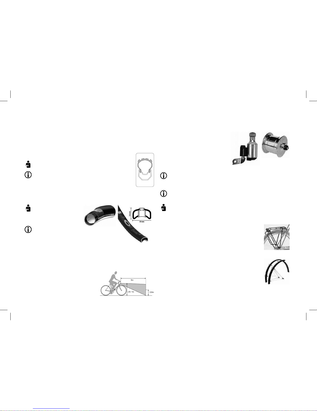
Regulations). This includes white front and rear lights powered by a xed dynamo (6V, 3W), a clearly
audible bell and reectors. The reectors have to be set up as follows: front – white, large, may be
integrated into the light; rear – two red reectors, one may be integrated into the rear light; wheels
with two yellow reectors per wheel, alternatively white reecting rings in the tyre, rims or spokes;
peddles with one yellow reector per peddle – one reecting forwards and one reecting backwards.
Only racing bicycles weighing less than 11 kg are allowed to use battery-powered head and rear
lights, and these must be carried with the bicycle at all times. All other bicycles have to use dynamo-
driven lights and each lighting system has to carry a stamp of ofcial approval. Here, the StVZO
applies. When making technical changes to the components on your bicycle, please note that
electrical parts may only be replaced with type-tested components.
Participating in public road trafc in Austria requires riders to comply with Act 146 / the so-called
bicycle act (Fahrradverordnung). This is outlined in the Austrian Federal Law Gazette (Bundesge-
setzblatt). Please ensure that before every ride your bicycle is in a roadworthy state, that the brakes
are perfectly set up and that the bell and light system comply with the StVZO. Only racing bicycles
weighing less than 11 kg are allowed to use battery-powered head and rear lights, and these must
be carried with the bicycle at all times. All other cyclists have to use dynamo-powered lighting sys-
tems, with every system having to hold the national seal of approval. The StVZO is applicable here.
When making changes to the components on your bicycle, please note that electrical parts may only
be replaced with type-tested components.
Complying with regulations
Usually, bicycles are intended for transporting one person at a time. If you are planning to transport
additional people or baggage then the regulations of the StVO apply. Here there are specic weight
restrictions depending on the size and type of the bicycle as well as the location of the rack (see
“technical information”).
If they are set up as stipulated by the StVZO,
Trekking bikes / ATBs are allowed to be ridden on public roads, paved trails and unsurfaced routes
City, touring, sports, childrens and youth bikes can be used on public roads and paved trails
Racing bikes/tness bikes can be used on public roads for training purposes. They may only be
ridden on asphalt surfaces!
Mountain bikes may be used off-road and on non-paved tracks. They may NOT be used in races
or for downhill! These types of bicycles are only permitted on public roads after the compulsory
equipment has been tted!
The guidelines laid down in the StVO and StVZO do not generally apply when using your bicycle in
competitions. However, all guarantees and liability regulations only apply as long as the bicycle is
being used in accordance with its conditions of use and safety guidelines. Otherwise all liability for
the manufacturer and retailer is nullied. This includes carrying too much weight on the bicycle, not
properly repairing damage, using the bicycle off-road and in competition as well as all uses not in
line with the conditions of use. This always includes:
Carrying too much weight•
Improper repairs of damage•
Use in competitions,•
as well as not adhering to the conditions of use and maintenance, doing jumps, riding down steps
and anything else that places extreme stress on the bicycle.
Instructions relating to your own safety
Every type of bicycle has a different load capacity which is listed in the “Technical information”
chapter. If a bicycle is subjected to excess load, this can lead to breaks in the handlebars, fork or
frame, for example. The maximum permitted load for the rack is usually stated on the rack itself. If
this is not the case, the maximum permitted amount for your rack will be listed in the “Technical in-
formation” chapter. Not all bicycles are suitable for installing children’s seats or bicycle trailers – your
specialist retailer can advise you in this area. In particular, frames and components made of carbon
are completely unsuited to carrying this additional weight! Bent or damaged components have to
be replaced; they could contain hairline cracks or be broken following a fall. Continuing to use them
could cause serious injury. Different types of rims (carbon, aluminum) require different types of brake
pads to work efciently. Otherwise this can cause accidents.
Please take your bicycle to a specialist to carry out repairs, servicing and setting up parts of the
bicycle.
As a rule, the following applies:
You should ride carefully in wet conditions, particularly those covered in wet leaves in autumn.•
Brake earlier and ride slower as the braking distance is considerably longer in these conditions.
Do not only use your lights when its dark, you should also use your lights at twilight and in foggy•
or rainy conditions. You can see and be seen better.
Do not overestimate yourself: your speed should match your abilities both on public roads as well•
as off-road.
The setup and functionality of the bicycle could change during transport – despite multiple checks
being carried out during production and the nal post-production check. Therefore, check the
following before the rst ride:
Screws, bolts and pedals are all secure•
Stem, handlebars and seat post are all safely secured and adhere to the minimum insertion length•
Test the setup of the brakes and their effectiveness•
Check that the wheels and quick releases are secure•
Check that the suspension components are working properly•
Gears and lights•
Air pressure and tires•
• Check the quick release locks before every ride, even if your bicycle was only left unatten-
ded for a short period of time!
Generally, a bicycle will change most in the rst 100 kilometers; the spokes will bed in, the brake
cables and gear cables settle into the housings and the bearings are broken in.
Therefore, it is important that you have your rst inspection carried out by a specialist retailer after
200–300 kilometers or 4–6 weeks. This should encompass:

Before the rst ride
5
Checking the wheels, which should be tensioned and trued as required•
Oiling the chain and gear system•
Checking that screws, bolts and quick releases are secure•
Checking the torques (pedals, cranks, handlebars, seat)•
Checking the headset, brakes, gears and suspension parts, adjusting them where necessary•
When working on your bicycle, please ensure in particular that all screws that are key to safety are
secured with the correct torque. The required torque is printed on many components. This amount is
stated in Newton meters (Nm) and this work should be carried out using a torque wrench. The best
sort of torque wrench for this is one that clicks when it reaches the prescribed torque. Otherwise
screws can snap or break. If you don’t own a torque wrench then you should always leave this work
up to a specialist retailer!
A table listing the most important torques for bolted connections is provided in the “Technical
information” chapter.
Before the rst ride
Please ensure that the bicycle is ready for use and adjusted to t your body. That means: adjusting
the positioning and mounting of the seat and handlebars, assembling and setting up the brakes and
ensuring the wheels are properly fastened in place.
Move the handlebars and stem into a safe and comfortable position for you. Please refer to page 6
for instructions on how to adjust the handlebars. Adjust the seat to a safe and comfortable position
for you. Please refer to page 5 for instructions on how to adjust the seat.
Please ensure that the brakes are always within easy reach and that you understand the position
and functionality of the brake handles on both the left and the right! Ensure that you know which
lever operates which brake!
Modern braking systems might be more powerful than those that you have used before.
Please get to know the brakes on a safe piece of land before setting off on your rst ride with the
bicycle!
Please ensure that the wheels are safely fastened in the frame and fork. Check that the quick
release for the seat is tight as well as all important nuts and bolts!
The “Technology” chapter contains instructions on how to safely use the quick releases, while “Tech-
nical information” contains a table with the torque of important nuts and bolts.
Check the air pressure in the tires. If you place your thumb on the pumped up tire, you should not be
able to bend the tire very much, even when a lot of force is exerted.
Check the tires and rims for damage. If you can see cracks, holes or tears then do not ride the
bicycle!
Check: The frame and fork must not be misshapen or damaged.
If you have doubts about whether your bicycle is in perfect technical condition, do not ride it. Please
have it checked by a specialist retailer!
Before and after every ride
Check that the:
Lights and bell are working and safely secured•
Brakes are working safely and are properly secured•
Tires are free of foreign objects and damage, and that the rims are not damaged and run true•
(particularly after riding off road)
Suspension components are working properly and are safely mounted•
Gears are working properly and are secured•
All quick releases are secured•
Frame and fork are not misshapen or damaged•
If you are unsure of whether your bicycle is in a sound technical state, take it to a specialist retailer
to be checked!
Adjusting the bicycle to the rider
Height of the frame, seat and handlebars
A bicycle has to t your physical dimensions for you to feel comfortable on it!
The frame size of your bicycle is determined according to your size. You should consult a specialist
retailer when selecting your frame. Your comfort and ability to perform on the bicycle are ultimately
and largely dictated by setting up the perfect seating position.
Please ensure you read the instruction manual supplied by the component manufacturers for
each component. Only use the correct torque for tightening the important bolted connections.
Please adhere to the prescribed torque of each bolt!
This is done as follows:
The height and tilt of the seat are important. The seat should usually be set
up to be level (parallel to the ground) or tilting slightly backwards. However,
you must nd the position that is most comfortable for you, which comes
with experience. Your specialist retailer will be happy to help you set up a
good seat position. You are able to adjust the height of the seat post with
the seat bolt or quick release.
Quick releases
Use quick releases with great care; they are key to your
safety on the bicycle and are located on the front wheel, rear
wheel and possibly even the seat tube.
Aside from the locking nut, which allows you to regulate the
clamping force, the quick release also has a clamping lever,
which converts the closing movement into clamping force.
To open the quick release, the clamping lever has to be
opened 180° degrees, revealing the word Open. To close
the release, simply close the lever 180° back to its original position,
allowing you to read the word Close.
A good gauge for measuring if the wheel is safely clamped is if you can only close the clamping
lever with the balls of your hands with a moderate amount of pressure. You should then feel an
possible positions
of quick releases
Tilt of the seat

Setting up the seat height
6
increasing amount of resistance after closing the lever about half way. If
the component is not properly or insufciently fastened, turn the opened
quick release lever clockwise by half a revolution. Then close the lever
and test if the wheel is now tightly attached. If the component is not tight
or securely tightened enough, then open the quick release lever and
rotate it clockwise by 180 degrees. Then close the quick release lever
and test the component again for tightness.
For example: Grip the front and rear wheels on the tyres and shake them
strongly in a lateral motion. The wheels should remain tightly in place.
When closed, quick release levers should be at against the frame,
fork or seat post and should always point backwards! This ensures
that they cannot be opened through contact during riding.
More information about quick releases is provided in the “Technology” chapter.
Check that all quick releases are properly fastened before every ride!
Setting up the seat height
There is a simple process to test the height of your seat: Sit on the seat and the heel of your fully
stretch leg should sit on the pedal at the bottom of its cycle. In contrast, with the balls of your feet on
the pedals, your leg should be slightly bent when the pedals are at their lowest point.
When adjusting the height of the seat, you must leave a minimum insertion length of 7.5 cm (10 cm
for longer seat tubes that stick out above the level of the top tube). This minimum insertion length
is usually clearly indicated, and it is very important for your safety! The seat clamping bolt is either
opened anti-clockwise and closed clockwise with an allen key; or it is attached to a quick release
mechanism. The same applies when adjusting the tilt of the seat.
Please ensure you use the correct torque for the bolts!
Suspension seat posts, which are designed to take some pressure off the spine, should be
set up by your specialist retailer.
The handlebar assembly consists of the stem, the handlebar itself, controls and the headset.
The position of these components has a great inuence on your ultimate seating position and the
resultant posture. Ultimately, the seating position is governed by the height difference between the
handlebars and the seat. Low handlebars increase the pressure on the upper body, arms and wrists,
while higher handlebars put more load on the spine. The best way to nd the best setup for you is
with the help of a partner who holds the bicycle in place while you bend your upper body forward
bit by bit while sitting on the bicycle and stretching your hands towards the handlebars. Specialist
retailers can also be a good source of advice here too.
Setting up the handlebar position
When setting up or adjusting the position of your handlebars, it is vital to ob-
serve the 6.5 cm minimum insertion length of the handlebar stem or observe
the STOP marking on the stem – otherwise the stem could be unstable.
With conventional handlebar stems, you rst have to loosen the stem spindle
with an allen key anticlockwise, while holding the front wheel between your
knees. Twist the stem shaft back and forth or knock on the spindle with a
plastic mallet from above until the clamping screw is released. Then adjust
the stem to the desired height and orient the handlebars so that the stem
forms a right angle with the frame. Then tighten the spindle clockwise with the allen key (take note
of the correct torque!).
The height of A-head systems should always be adjusted by specialist
retailers.
The same applies for setting up adjustable stems. They have to be adjusted
by specialists.
Adjusting this part of the bicycle incorrectly could lead to very serious falls
and injury!
The alignment of the handlebars in their horizontal position can be changed
by loosening the lock bolts on the front side of the stem in a clockwise direc-
tion, adjusting the position of the bar as desired and then tightening the screw
back to the prescribed torque. Please ensure that the handlebars are exactly
in the middle of the stem.
If your bicycle is equipped with an adjustable stem, you can adjust the height
and distance to your handlebars as you wish. This is done by changing the
tilt of the stem.
To do this, loosen the allen bolt located on the side of the stem by turning it
several times with an allen key. You should now notice that you are able to
move the stem. Please ensure that you do not turn the screw so much that
the individual parts of the stem fall apart. When the internal locking system
is loose enough, you should be able to move the stem upwards and down-
wards. Move the handlebars into the desired position and tighten the allen
screw again. The required torque is stated on the side of the stem.
Please note that this process also twists the handlebars. Now you have to
adjust the handlebars into a position in the stem in which you can easily and
safely operate that brakes and gears! A brief instruction on how to do this is
outlined in the section “Adjusting the bicycle to the rider”.
Horizontal seat
position
Tilt of the seat Maximum insertion
length
Seat clamping
screw
Seat quick
release
Quick release
Stem
A-Head stem
Stem cap
A-Head stem

Components of the bicycle
7
Components of the bicycle
Bottom bracket and cranks
The bottom bracket, crankset, gearside, chain and pedals form the bicycle’s
drive train. The bottom bracket consists of an axle, ball bearing, sealing rings
and bearing shells. These are contained in a unit known as a sealed bottom
bracket. This is enclosed and set up in the factory in such a way that it requi-
res no maintenance.
It is important that the cranks and bottom bracket do not exhibit any play
and are secure; these have to be regularly checked, otherwise there is
a danger of failure and accidents.
It is key that the cranks and bottom bracket are tight and secure, and this
should be checked on a regular basis to avoid any risks of breaking. The crank
bolts have to be tightened at the rst inspection (after approx. 100 km). When
doing this, please refer to the table in the “Technical information” chapter and
the instructions provided by the respective manufacturer of your components. The useful life of the
chainrings is largely dependent on care and maintenance, as these parts are subject to wear.
Pedals
Normal, platform and clipless pedals are types of pedals that sometimes require specialist footwear.
Standard shoes can easily slide off the pedals, but specialist shoes also require practice, as it is
easy to fall off the bicycle before you are familiar with how they work. Shoes for system pedals are
attached to the pedal with a safety release, in a similar way to ski boots in skis. This connection is
released by twisting the heels sideways. You can set how much power is necessary to release the
foot from the pedal.
Ensure that you read the manufacturer’s instructions before using clipless pedals. Operating
this system should be rst practiced and mastered in standing before riding the bicycle on
roads.
If your DHM bicycle is equipped with quick release pedals and quill pedals
(clips and straps), practice getting your feet in and out of the clips and using
the straps on a safe and quiet piece of land before the rst ride. Tightly
secured pedal belts do NOT allow you to release your feet! Never practise this
in road trafc, otherwise this can lead to falls and serious accidents. Please
practice on a safe piece of land rst.
Pedals are marked with “L” (left) and “R” (right). The right pedal (“R”) is threaded
into the right crank clockwise with the right thread, while the left (“L”) is threaded
anticlockwise into the left crank with the left thread – both with a 15mm wrench
towards the front wheel. Warning: Screwing the thread into the crank at an angle can render
the thread useless. Pedals have to be screwed in very tightly. Failure to do this increases the
risk of accidents!
If your DHM bicycle was supplied without the pedals pre-installed, these have to be attached with a
suitable wrench.
Clipless pedals which do not properly release are a safety hazard. Danger of falls!
Gears and chain
The gears allow you to change the drive of your bicycle to t your terrain and personal requirements.
This part of the bicycle governs the relationship between the tempo of the pedaling and the speed of
the bicycle. You have to pay close attention to the manufacturer’s instruction manual both for internal
hub gears and external chain gears. You can read about this in the “Technology” chapter.
When using the standard commercial derailleur gears, there are several important rules aimed
at making the components durable and promoting safety, and these should always be observed:
Please do not use broken, worn or loose components – they can cause injury and should be
replaced or adjusted by a specialist retailer. You should also contact a specialist retailer if you hear
any unusual noises, notice that the gears are not changing smoothly or if the chain is showing signs
of wear!
A broken chain or gear system can lead to serious falls.
Operating derailleur gears
Always avoid using the smallest rear chainring with
the smallest front chainring at the same time, and the
same applies for the two largest. This exerts just as
much strain on the chain as it does on the chainrings –
it will wear quickly and can easily come off. You should
also not pedal backwards while changing gear as this
can seriously damage the gear system. And nally: use
a spoke protector – this reduces the risk that the chain
will slide between the spokes and chainring, damaging
the spokes. Take great care when switching into the
lowest gear with the largest rear chainring.
In the chain gear system, there is a right gear shifter for the rear derailleur and left one for the front
derailleur. It is important to keep pedaling evenly and not operate both shifters at the same time.
Very important: the chain should be oiled regularly. This is particularly vital after riding in the rain.
Gears with a large chain misalignment place a lot of strain on the chain. Whatever the case, chains
reach their wear limit after around 2000 km with chain gears and 3000 km with hub gears. At that
point, the chain should be changed.
Changing a chain requires specialist tools. Leave it up to your specialist retailer to select the chain
and t it.
Brakes
The legal requirements for your bicycle’s brakes are
prescribed in article 65 of the StVZO. There are different
types of brakes depending on the type of bicycle. The
main categories are rim brakes, drum brakes and disc
brakes. For more information on operating and taking care
of the brakes, please refer to the manufacturer information
as well as the “Technology” chapter.
Be careful! Hub and drum brakes can only be retrotted if
the fork has the “N” symbol. Long periods of braking heat up hub brakes, redu-
cing their effectiveness. Adapt your riding style to account for this!
Crank
Pedal and
clipless system
Rear derailleur
Front derailleur
Disc brakes
Rim brakes

Components of the bicycle
8
The factory set brakes have to be checked before the rst ride.
To do this, please pull hard on both brake levers in standing and try to push the bicycle. The wheels
should not turn. You should also not be able to pull the brake lever all the way to the handlebars.
If the brakes are not working properly, you are not allowed to ride the bicycle! Otherwise you run a
great risk of falling and sustaining serious injury! Brake pads and cables are subject to wear and
therefore have to be serviced and replaced.
Rim brakes and rims subject wear on each other. Fine cracks can also occur on
rims, or rim anges can become misshapen when air pressure is increased. You
can reduce this wear by riding conscientiously, not braking too hard or for long
sustained periods.
The brake pads have to be regularly checked or replaced. This also applies to
the rims, if your bicycle has rim brakes.
Legislation stipulates that rims have to have wear indicators in the form of a
groove or easily visible dots. If these indicators can no longer be seen in just
one area, then you should immediately have the rim changed by your specialist
retailer!
If you are using your bicycle off-road, this also increases the stress for frames and components. As
a result, you should check the technical condition of your bicycle more thoroughly and regularly.
Disc brakes
If your bicycle is tted with disc brakes, congratulations – you have purchased the most up-to-date
and best type of brakes available for bicycles.
Please note that a disc brake system may be far more powerful than you are used to!
Please practice using your new disc brakes before your rst ride and before using the bicycle on
public roads. Disc brakes are also more effective in wet conditions than all types of rim brakes.
To get the most out of your brakes, please note the following:
You can adjust the gap between the brake lever and the handlebars to suit the size of your hands.•
Braking is safer if the brake levers have been adjusted to the right size for you.
New brake pads have to brake hard 10 to 20 times from a speed of 30 km/h before they reach •
their full potential. It is recommended you do this, but with extreme care. Look for a quiet location
without trafc and ensure that you always keep your bicycle under control.
If you are transporting your bicycle with the wheels removed, do not pull on the brake levers. This•
can lead to unwanted air in the system or that the brake pads are pressed too far together. Install
a barrier between the brake pads if you remove the wheels.
Please check the brakes and brake lines regularly for escaping brake uid. If you notice that brake
uid is escaping somewhere, please refrain from using the bicycle and take it to your specialist
retailer for checking. Hydraulic brakes with an open or leaky system are unable to build up sufcient
brake pressure and are therefore unable to brake safely!
Please check the thickness of the brake pads before every ride. Pads less than 0.5 mm thick have
to be replaced before starting the ride.
Never touch the brake disc of a rotating wheel. You can suffer serious injuries if your nger is caught
in the rotating disc!
Brake disks and callipers can get hot under braking. Never touch the brake disk or calliper after you
have braked. You are in danger of suffering burns.
Never touch the brake disk with your hand, as it must remain free of all lubrication. This is the only
way for you to brake safely.
Bent brake lines should also be checked by a specialist immediately.
Avoid contact with the brake uid! It is corrosive and poisonous and is capable of damaging your
health and property!
There are many different models of disc brakes, with their operation, maintenance and setup greatly
varying. Please make sure to inform yourself by reading the enclosed instruction manual. Detailed
information is also provided on the manufacturer’s websites:
http://www.magura.com/de/produkte/scheibenbremsen-2010/prod/louise-30/info/downloads.html,
http://www.sram.com/en/XX/products/brakes.php
Headset
The headset is the bearing for the fork in the frame. Road shocks place a large
amount of pressure on this component, moving it or loosening it. However, it is
important that it turns easily and is not at all loose. You can check this yourself
by wrapping your ngers around the lower bearing shell, pulling the front brake
with your other hand and pushing the bicycle back and forward. If you can feel
the bearing moving then it has to be adjusted. To check how easily the bearing
moves, you have to lift the front wheel up with the frame and you should be
able to easily turn the fork of the front wheel to both sides with just two ngers.
The same applies here: Required modications should be carried out by
specialists as special tools and experience are required to do this. If you want
to carry out the work yourself, please pay close attention to the information
provided by the manufacturer. Improperly setup headsets can lead to breaks and falls.
Frame
Various materials, such as aluminum or carbon, are used to build frames. Carbon is a very special
material which doesn’t always clearly show signs of damage sustained during use when the bicycle
falls over or you crash. Some deformations, fractures and brous cracks can only be identied
through closer inspection. As a result, the torque for bolts in/on carbon frames
and components is sometimes substantially lower than is the case with other
materials. Children’s seats are not allowed to be tted to carbon frames. Miss-
hapen carbon components have to be replaced. Precise and regular checks
by a specialist are essential for bicycles built out of this modern material!
A properly set up frame ensures that your bicycle will ride in a straight line.
Your specialist retailer is able to test the bicycle’s track. Both stipulate how the
bicycle behaves during riding and how comfortable it is to ride. Every frame has
a frame number. This is either located on the rack xture, on the seat tube or the bottom bracket
shell.
It is vital to check the frame thoroughly after a fall; bent or broken parts can cause serious injuries!
These may not be repaired but have to be replaced, otherwise there is an increased risk that they
might break.
Fork
The front wheel and brake are attached to the fork.
The fork consists of the fork blades, fork bridge and steerer. Damaged or bent
forks should always be replaced otherwise there is an increased possibility of
serious accidents! In order to increase riding comfort, many bicycles are equip-
ped with a suspension fork. To set up the various different models (Air/oil forks,
elastomer fork, steel spring fork), please refer to the information provided by the
manufacturer or contact your specialist retailer.
The websites of the respective suspension manufacturers are also a great
Rim with wear
indicator
Headset
Carbon frame
Carbon fork (left),
Suspension fork (right)

Wheels, tires, air pressure, valves
9
source of extra information. On www.magura.de for instance, you will nd detailed information on
using and setting up suspension forks and disc brakes.
Frames with rear suspension
If you want to experience a particularly sporty or comfortable ride off-road
with your DHM bicycle, then perhaps you opted for a full suspension
model. This means that the rear part of the main frame is not rigid but
exible and damped and cushioned by a shock absorber. This type of mo-
del doesn’t just offer increased riding safety and comfort, it also requires
special care when using it. This instruction manual is only able to discuss
general key topics. If you would like more detailed information and advice
then please read the enclosed manufacturer instructions for the shock
absorber and speak to your specialist retailer. The website of your respective
suspension manufacturer could also be a useful source of information. On www.sram.com/rockshox
for instance, you can nd detailed information on how to use and set up the rear suspension.
The specialist retailer should have set up the suspension for you before handing over your new
DHM bicycle. Don’t be surprised if the bicycle and seating position are different and if they feel
different to what you are used to.
The suspension struts have to be set up to be soft but not so soft that they overtravel when you
drive over an obstacle. Therefore the bicycle should only lower a little when you sit on it.
Please ensure that you read the enclosed instructions provided by the manufacturers on suspension
and shock absorbers.
Care and maintenance
You can clean a full suspension MTB as you would a conventional bicycle, using warm water with a
little washing up liquid or weak cleaning agent that can be purchased from your specialist retailer.
You should avoid washing your bicycle with a high pressure cleaner, as this forces cleaning uid at
high pressure into insulated areas and damages them.
The shaft and seals of the shock absorber themselves should be carefully wiped with a soft cloth as
part of your regular bicycle care. If you spray a little lubricant onto the surfaces of the suspension
and the gasket, they will work better and last longer.
There are special lubricants made for this purpose, such as Brunox.
You should regularly check the xtures at the rear of the bicycle for any looseness. To do this, pick
up the bicycle and try to waggle the rear tire laterally. Also, by picking up and then quickly putting the
rear part of the bicycle back down, you can check if the xing sockets of the suspension are tight. If
you feel any looseness anywhere or can hear rattling, you should have your bicycle checked by a
specialist retailer at once.
It is vital for your safety that the suspension elements are working properly and are tightly tted!
Clean and check your full suspension bicycle on a regular basis!
Wheels, tires, air pressure, valves
The wheels form the only points of contact between your bicycle and the ground.
They consist of rims, hubs, spokes, rim tape, inner tubes and tires. They are put
under great pressure by the weight of the rider and the road conditions. Checks
and maintenance are therefore essential. In addition, the spokes should be
retrued by a specialist after being ridden in (after approx. 100 km).
Rims are subject to friction from rim brakes.
They are therefore subject to wear; the strength of the rims, which can be checked by specialists
using a special measuring device, may not fall below a critical level. You should have this checked
after every second set of brake pads. The wear of aluminum rims (from 24”) can be detected by
analyzing wear indicators.
Even if these are only showing signs of wear in one place, the rims have to be replaced! The hubs
should be adjusted by a specialist if you can detect any play. To detect play, you have to grip the
front wheel in the fork or the rear wheel in the rear stays on the rim or tire and try moving from side
to side at a right-angle to the wheel. This will easily allow you to feel any looseness at the hub.
Seek advice from a specialist retailer when selecting your type of tire, because this is closely linked
to the type of riding you are expecting to do with the bicycle. After all, the tires are responsible
for providing grip and traction in corners, under braking and acceleration on the different types of
terrain. The rolling resistance and off-road capabilities are majorly dictated by the tire prole. It goes
without saying that the inner tube also has to match the dimensions of the tire. These dimensions
are given in millimeters (width and diameter e.g. 622-23) or in inches, e.g. 28 x 1.60. The required
air pressure is also printed on the tires, and is displayed as a conversion from PSI to bar.
You can nd more information about how to convert PSI into bar in the table in the “Technical
information” chapter.
The maximum air pressure may not be exceeded as this can cause the tyres to explode and result
in injury!
Tire pressure that is too low is also dangerous, as the tire does then not have enough grip on the
rim.
As a general rule of thumb, mountain bike tyres have a safe air pressure of 2.5-3 bar, trekking, city
and touring bikes approx. 3.5 bar and racing bikes around 6.7 bar.
If you have to change a tire, be careful to replace it with another tire with the appropriate type and
dimensions!
There are now 3 different types of valves on the market. The valve
is protected again dirt by a protective cap. These valves allow you to
pump air into the inner tube and are protected from dirt by a small cap.
Dunlop quick release valves and Schrader valves can be lled with air
after the cap has been removed and a tting pump allied. In the case
of Sclaverand / racing valves, a small nut rst has to be screwed on
and pressed for a short time, allowing some air to escape. You can
avoid tting your tires the wrong way round by always ensuring that
the quick release lever is on the other side to the chain gear system. If
your wheels are protected by cap nuts, it is important to adhere to the
correct order of nut, fail-safe mechanism and locknut.
Rear shock absorber
Wheels
Information on tyres
Bicycle valve

Disk wheels, specialist wheels
10
Disk wheels, specialist wheels
If your DHM bicycle is equipped with disk wheels, trispokes or other specialist wheels, please read
the instructions provided by the manufacturer carefully regarding their use and care.
ABB Hazard Special wheels can exhibit a different riding, braking and steering behaviour than what
you are used to. Trispokes and disk wheels in particular are substantially more sensitive to wind than
conventional wheels. If the rims are not aluminium, they may have a different, possible substantially
worse braking behaviour than you are used to. Practice on a safe, trafc-free piece of land with your
new bike and get used to how it behaves. Otherwise this can lead to falls and serious injury.
Tubeless tyres
If your DHM bicycle is tted with tubeless tyres, please read the instructions provided
by your manufacturer covering the tyres and rims.
Tubeless tyres may only be used on rims intended for this purpose! This will
be marked on the rims, with the abbreviation “UST” for instance.
Tubeless tyres may only be used with the correct air pressure and the recom-
mended sealant (if required).
The installation and removal from the rim may only be done without tools in the
case of tubeless tyres. Otherwise this could lead to weaknesses. If you do not have
sufcient sealant for preventing damage, a normal tube can be used after removing
the valve from the tubeless system.
Tubular tyres
Tubular tyres may only be used on
rims intended for this purpose! The
corresponding rims do not have rim
anges but smoothly curving sur-
faces, from the outside inwards.
Tubular tyres may only be used in
the prescribed way and with the
correct air pressure! Attaching tubular
tyres requires expert skills and lots of
experience. Therefore always have
your tubular tyres changed by a specialist
Lights
Safety on a bicycle revolves around SEEING and BEING SEEN. That’s why bright clothes, reectors
and working lights are vital. It goes without saying that you are not allowed to keep riding at night if
your lights stop working!
Only legal and approved light systems can be tted to
the bicycle. This also applies for luminescent substances
and reectors. The StVZO prescribes a light setup where
the middle of the light cone is half as high as the level of
the light. The rear lights have to be attached at a height
of at least 25 cm. Racing bicycles weighing less than 11
kg may be used without xed lighting. However, riders
have to carry battery-powered lights with them!
Bicycles weighing over 11 kg have to use approved (with ofcial approval seals) dynamo-based
systems. Dynamos are xed either laterally or as hub dynamos. Lateral dynamos may only be
switched on in standing for safety reasons; they are less effective in the rain and sometimes require
additional lighting.
Hub dynamos are more effective and subject to less
wear (please note: high voltage, do not touch the
clamps while the front wheel is turning!). They can
also be tted with additional sensors for automatically
turning the system on during darkness or an on/off
switch on the handlebars. Please ensure that when
you remove the front wheel, you disconnect the con-
nection clamps for the hub dynamo rst. Then ensure
you connect these on the right hand side (when
facing forward) when tting the wheel again.
Please pay attention to the enclosed instructions for your lighting system. In the case of con-
ventional lights, the cause of a fault can be the light bulb. You can check and replace the bulb
yourself if you feel that you are capable of doing so. Replacement bulbs can be purchased
from specialist retailers. You are not able to replace the light elements in modern LED lights.
Clean your reectors and lights on a regular basis. Warm water mixed with cleaning or
washing up liquid is ideal for this. You are able to keep the contact points in good condition
with a suitable spray lubricant.
A working lighting system is vital. You should allow you specialist retailer to carry out any
checks and repairs.
Add-ons
Rack
Racks are usually categorized according to four weight classes (DIN 79121): 5
kg, 10 kg, 18 kg, 25 kg. Other limits apply for special builds.
Warning: Extra weight can considerably change the way your bicycle behaves
during riding. The braking distance is increased! Please also ensure that you
stay within the maximum permitted total weight for your bicycle. In principle,
racks can be mounted at the front or at the rear; while children’s seats should
be installed with special holders at the rear.
Mudguards (fenders)
Ensure that the mudguards on your bicycle tted correctly, ensuring that their
lower edge is parallel to the edge of the tire. Mudguards can be made of either
metal or plastic and they are held in position by stays. In order to prevent the
front wheel from jamming due to foreign objects picked up, the front wheel
stays have a release mechanism. You should regularly check that mudguards
are securely fastened, and loose stays have to be secured again or replaced.
Damaged mudguards have to be replaced, as loose mudguards can cause
falls!
Tubeless
tyres
Tubular tyres
Hub dynamo
Dynamo
Rack
Mudguards

Add-ons
11
Parking stands
Parking stands allow you to easily park your bicycle. There are various different types:
double stands (right diagram) and side stands (see pictures). Double stands offer more
safety for city or touring bicycles, especially if the bicycle is carrying additional weight.
Never let children sit on their own on parked bicycles; this could easily cause a fall! You
also have to be very careful parking your bicycle when it is carrying extra weight in the
form of luggage. Weight attached higher up the bicycle makes it easier for the bicycle to
tip over.
Aerodynamic clip-on bars
If you ride your bicycle with aerodynamic clip-on bars (“triathlon bars”), ensure that you familiarise
yourself with their behaviour on a safe piece of land before taking to the open roads. In particular,
the distance to the brake and gear shift levers could be considerably longer. The steering behaviour
is also different to what you are used to.
Bar ends
If you t your DHM bike with so-called “bar ends”, the handlebars have to be approved for this. Allow
a specialist retailer to judge whether you are permitted to install bar ends and attach them yourself.
Additional parts installed on the handlebars have to be securely tightened, otherwise this
could result in falls. Please read the instructions from the component manufacturer carefully.
Bar ends can negatively impact the steering behaviour of your bicycle and your ability to
brake. Practice using them before your rst ride and ensure that your reactions are not
negatively affected.

Technology
12
General Safety Information
WARNING
This wheel is equipped with a quick release hub to facilitate installation and removal. Failure to•
properly install this quick release hub (wheel) onto your bicycle may cause the wheel to become
detached from the bicycle while you are riding and result in serious bodily injury.
Use a front fork which is equipped with a wheel retention mechanism.•
BEFORE USE, CAREFULLY READ THE QUICK RELEASE SERVICE INSTRUCTIONS IN•
YOUR OWNER’S MANUAL. IF YOU HAVE ANY QUESTIONS, ASK YOUR DEALER. IMPROP-
ER HUB INSTALLATION CAN RESULT IN SERIOUS BODILY INJURY.
Read these Technical Service Instructions carefully, and keep them in a safe place for later refer-•
ence.
CAUTION
Be sure to operate the quick release lever by hand only. Never use any other tool such as a ham-•
mer to tighten the quick release lever, as this could cause damage to the lever.
Note
Parts are not guaranteed against natural wear or deterioration resulting from normal use.•
What is a Quick release?
It is a mechanism that uses a single quick release lever operation on the hub to enable the wheel to
be easily installed and removed.
Quick release function
When the quick release lever is brought to the closed position, the lever nut moves inward. The
force of this clamps the wheel to the frame and holds the wheel securely in place.
The clamping strength is adjusted by turning the adjusting nut. When the nut is turned in a clockwise
direction, the clamping strength increases, and when the nut is turned in a counter-clockwise direc-
tion, the clamping strength decreases.
Suitable dimensions of the fork end
Be sure to use only fork widths with suitable dimensions.
Front – cannot use fork thicknesses less than 4
mm. (Dura-Ace, 600 Ultegra: not less than 5 mm.)
Rear – cannot use fork thicknesses less than
5 mm. (Dura-Ace, 600 Ultegra: not less than
6 mm.)
Operation method
The front axle is explained as an example. The rear axle works in the same way.
Quick release

Technology
13
Move the quick release lever to the OPEN position and set the wheel so it rmly touches the 1.
interior of the fork end (See sketch below).
Open and close the quick release lever with your right hand while gradually tightening the adjust-2.
ing nut (located on the opposite side of the hub) with your left hand in the clockwise direction.
Continue tightening the nut until you feel resistance with your hand at the point when the lever is
parallel to the hub (as indicated by the dotted position in the diagram on the right).
Grip the fork with your ngers and use the palm of your hand to close the quick release lever with 3.
as much strength as possible. When closed, the quick release lever must be in the “CLOSE” posi-
tion shown below in the diagram on the right. The side of the lever with the inscription “CLOSE”
must be facing away from the wheel, and the lever should be parallel to the fork as shown below
in the diagram on the left.
Notes
If the quick release lever can be easily pushed to the CLOSE position, this means the clamping
strength is insufcient. Return the quick release lever to the position perpendicular to the bicycle
frame and again turn the adjusting nut clockwise to increase the clamping strength. Push the quick
release lever back to the CLOSE position.
If the clamping strength is adjusted too strong and the quick release lever cannot be pushed to
the CLOSE position, turn the adjusting nut in a counter-clockwise direction to reduce the clamping
strength. When doing this, do not fully release the adjuster nut. Turn it 1/8 of a revolution, and then
try to push the lever to CLOSE, to set the maximum clamping strength with which you can push the
quick release lever to the CLOSE position.
Positioning of the quick release lever
For safety, the quick release lever should be along the bicycle frame when in the CLOSE position.
How to fasten this quick release hub
Positioning of the quick release lever

Technology
14
Move the quick release lever from the CLOSE position to the OPEN position.
Loosen the adjusting nut, and then remove the wheel.
WARNING
THINGS TO CHECK BEFORE RIDING
Always check your quick release hubs before riding1.
to make sure that the wheels are correctly installed
on the bicycle frame. This is especially important
after you park your bicycle in a public place.
Make sure that the quick release levers are pushed2.
fully to the CLOSE position (the side of the lever
with the inscription “CLOSE” must be facing away
from the wheel). As shown in the diagram. the lever
must be lifted, not rotated.
QUICK CHECK
Lift up the bicycle so that the wheel is off the ground, and give
the top of the tire a few sharp downward blows as shown in
the diagram. The wheel should not be loose or come off. This
check does not guarantee that the quick release lever has
received adequate tightening torque.
If you are uncertain as to whether the quick release is tightened
correctly, repeat the installation procedure as explained in “How
to fasten this quick release hub” of this service instruction.
General Safety Information
WARNING – To avoid serious injuries:
Improper use of your bicycle‘s brake system may result in a loss of control or an accident, which•
could lead to a severe injury. Because each bicycle may handle differently, be sure to learn the
proper braking technique (including brake lever pressure and bicycle control characteristics) for
your bicycle. Consult your bicycle dealer and the bicycle‘s owners manual, and practice your
riding and braking technique.
Be careful not to allow any oil or grease to get onto the brake shoes. If any oil or grease do get on•
the shoes, you should replace the shoes, otherwise the brakes may not work correctly.
Check the brake cable for rust and fraying, and replace the cable immediately if any such prob-•
lems are found. If this is not done, the brakes may not work correctly. Always make sure that the
front and rear brakes are working correctly before you ride the bicycle.
The required braking distance will be longer during wet weather.•
Reduce your speed and apply the brakes early and gently.•
If the road surface is wet, the tires will skid more easily. If the tires skid, you may fall off the•
bicycle. To avoid this, reduce your speed and apply the brakes early and gently.
Read these Technical Service Instructions carefully, and keep them in a safe place for later refer-•
ence.
NOTE:
If using SHIMANO‘s road brake shoes in combination with ceramic rims, the brake shoes will wear•
more quickly than normal.
If the brake shoes have worn down until the grooves are no longer visible, they should be•
replaced.
Parts are not guaranteed against natural wear or deterioration resulting from normal use.•
For maximum performance we highly recommend Shimano lubricants and maintenance products.•
For any questions regarding methods of handling or maintenance, please contact the place of•
purchase.
Brake shoe setting position
After adjusting the brake shoe position so that the shoe
surface and the rim surface are as shown in the illustration,
tighten the shoe xing bolt.
NOTE:
The BR-6600 allows the angle of contact between the shoe and the
rim (toe-in) to be adjusted. Adjusting the toe-in makes it possible to
obtain smoother braking operation.
Removing the wheel
If the quick release will not adjust properly, please contact a professional dealer for advice
Brakes

Technology
15
Cable connection
Set the quick release lever to the closed position; then adjust the shoe clearance (as shown in the
illustration below) and secure the cable.
Centering of the brake
Make a minor adjustment by using the centering adjustment bolt.
Readjustment of the shoe clearance
Turn the cable adjustment bolt to readjust the shoe clearance.
Remove the xing bolt1.
Remove the shoe by sliding it along the groove of the shoe holder.2.
There are two different types of shoe and shoe holder to be used in the left and right positions3.
respectively. Slide the new shoes into the grooves on the shoe holders while taking note of the
correct directions and bolt hole positions.
Tighten the xing bolt.4.
Replacement of the cartridge shoe

Technology
16
General Safety Information
WARNING
Improper use of your bicycle‘s brake system may result in a loss of control or an accident, which•
could lead to a severe injury. Because each bicycle may handle differently, be sure to learn the
proper braking technique (including brake lever pressure and bicycle control characteristics) for
your bicycle. Consult your bicycle dealer and the bicycle‘s owners manual, and practice your
riding and braking technique.
Be careful not to allow any oil or grease to get onto the brake shoes. If any oil or grease do get on•
the shoes, you should replace the shoes, otherwise the brakes may not work correctly.
Check the brake cable for rust and fraying, and replace the cable immediately if any such prob-•
lems are found. If this is not done, the brakes may not work correctly.
Always make sure that the front and rear brakes are working correctly before you ride the bicycle.•
The required braking distance will be longer during wet weather. Reduce your speed and apply•
the brakes early and gently.
If the road surface is wet, the tires will skid more easily. If the tires skid, you may fall off the bicyc-•
le. To avoid this, reduce your speed and apply the brakes early and gently.
Read these Technical Service Instructions carefully, and keep them in a safe place for later•
reference.
CAUTION
The power modulator is a device that makes it easier to control braking by increasing the cable
stroke at the brake lever within a certain constant range of braking force.
If the effective operating range of the power modulator will be exceeded, the lever stroke and the
brake will operate as a normal V-BRAKE brake (sensitive and powerful). In that case, the brakes
may operate more powerfully than intended and may cause the wheel to lock up. Therefore it is
essential that you fully understand and test the performance of the power modulator before use.
The power modulator is not equipped with a function to prevent the wheel from locking up.
Shimano BR-M770 Safety Information
WARNING – To avoid serious injuries:
The M770 brake system is equipped with an adjustment block in the wire hooking unit of the
BL-M770/ST-M770 brake levers which allows the rider to change the relationship between the
brake input and output. If the adjustment block is removed, the braking force will be dramatically
increased, so that a high level of braking performance can be achieved from only a small amount
of lever movement. Accordingly, normal braking operation may cause a greater-than-expected
amount of braking force to be applied, which could make the bicycle fall forward, causing serious
injury to the rider. To avoid this, please read the following instructions thoroughly before removing
the adjustment block.
After removing the adjustment block, make sure that you are completely used to the new
braking characteristics before riding the bicycle, otherwise the bicycle might fall forward if
you have to apply the brakes suddenly, such as when a vehicle appears.
Without adjustment block removed (standard specications for shipment)1.
With adjustment block removed2.
An ample degree of braking force can be obtained from a small amount of brake lever input, to
provide a high level of brake performance. However, if the brakes are operated suddenly, there is
the danger that the bicycle may fall forward.
After removing the adjustment block, rst ride the bicycle at a speed of less than 6 mph (10 km/h)
while applying the brakes repeatedly in order to get a feel for the difference in braking characteristics
before riding at higher speeds. Beginners should be particularly careful.
NOTE:
If the brake shoes have worn down until the grooves are no longer visible, they should be•
replaced.
Parts are not guaranteed against natural wear or deterioration resulting from normal use.•
For maximum performance we highly recommend Shimano lubricants and maintenance products.•
For any questions regarding methods of handling or maintenance, please contact the place of•
purchase.

Technology
17
While holding the shoe against the rim, adjust the amount of shoe protrusion by changing over the1.
washer B (thick or thin) so that dimension A is kept at 32 mm or more.
While holding the shoe against the rim, tighten the shoe xing nut.2.
Pass the inner cable through the inner cable lead, and after setting so that the total of the clearan-3.
ces between the left and right shoes and the rim is 2 mm, tighten the cable xing bolt.
Adjust the balance with the spring tension adjustment screws.4.
Depress the brake lever about 10 times as far as the grip and check that everything is operating5.
correctly and that the shoe clearance is correct before using the brakes.
Remove the shoe xing pin, and then slide the shoe along the groove to remove it from the shoe 1.
holder.
There are two different types of shoe and shoe holder to be used in the left and right positions2.
respectively. Slide the new shoes into the grooves on the shoe holders while taking note of the
correct directions and pin hole positions.
Insertion of shoe xing pin is very critical to keep shoe properly xed in place.3.
Setting up the brakes
Replacement of the cartridge shoe

Technology
18
General Safety Informatiojn
WARNING
Obtain and read the service instructions carefully prior to riding the bike• . Loose, worn or
damaged parts may cause the bicycle to fall over and serious injury may occur as a result. We
strongly recommend only using genuine Shimano replacement parts.
Obtain and read the service instructions carefully prior to setting up the parts• . If adjust-
ments are not carried out correctly, the chain may come off and this may cause you to fall off the
bicycle which could result in serious injury.
Before riding the bicycle, check that there is no damage such as carbon ber peeling or cracking. •
If there is any damage, replace with a new part immediately without trying to repair the damage,
otherwise the lever may break and the brakes may no longer work as a result.
Read these Technical Service Instructions carefully, and keep them in a safe place for later•
reference.
NOTE:
Use a soft cloth to clean the carbon ber levers, and be sure to moisten the cloth with neutral de-•
tergent before using it, otherwise the lever material may become damaged and lose its strength.
Avoid leaving the carbon ber levers in places where high temperatures are present. Also keep •
them well away from re.
Operation of the levers related to gear shifting should be made only when the front chainwheel is•
turning.
Parts are not guaranteed against natural wear or deterioration resulting from normal use.•
For any questions regarding methods of installation, adjustment, maintenance or operation,•
please contact a professional bicycle dealer.
Shifting and brakelevers
Operation of rear derailleur lever

Technology
19
Operation of front derailleur levers (FD-6700)

Technology
20
Installation of the brake cable
Table of contents
Other HM Bike Bicycle manuals