HMI TRU-FIT User manual

INSTALLATION INSTRUCTIONS
TRU-FIT
DOOR & PANEL
PARTS LIST
ITEM PART DESCRIPTION QTY
AZSS-4506 Wall Jamb 1
BZSS-4505 Hinge Jamb 1
CZSS 4504 Longer Piece = Wall Channel 1
DZSS 4504 Shorter Piece = Curb Channel 1
ECHG HGTW* Glass Hinge 2
FCHG BTB Back-to-Back Pull 1
GCMF Anchor Plastic Anchors for Wall Jamb 6
H#10 x 2” Wall Jamb Screws 8
JZV-935 Plastic Anchors for Channels 6
K#8 x 2” Wall and Curb Channel Screws 6
L#8 x 3/4” Hinge Jamb to Wall Jamb Screws 5
M#10 x 3/4” Heavy Glass Hinge to Post Screws 8
NZV 969 Adjustable Post Cap 1
O3/8” Clear Glass Door 1
P3/8” Clear Glass Panel 1
QSP-GSB125 Glass Blocks 6
RCHGP982 Bottom Sweep 1
SCHGP976 Angle Seal (Optional) 1
TCHGP972 Bulb Seal (Optional) 1
IMPORTANT NOTE:
Door should not be used for 72
hours in order to let silicone
cure properly.
When ordering repair parts, please provide the following information:
1. Model Number
2. Part Number
3. Part Description
4. Finish Color
Required Tools:
• TWO PEOPLE
• Pencil
• Tape Measure
• Electric Drill
• Phillips Head Bit
• Scissors
• Level
• Flat Head Screwdriver
• Hammer
• Silicone
• Painters or Masking Tape
• 1/8” and either 3/16” or 1/4” Drill Bits*
* Select the proper drill bits for your installation conditions
(i.e. tile, porcelain, marble, etc)
* The three pre-drilled holes and screws
go on the inside of the enclosure.
** The two screws on the outside of the
enclosure are optional, but
recommended for structural integrity.
V5_21_26
* Standard hinge part number listed. Reference original order PO for replacement parts.
Hinge styles may vary.

INSTALLATION INSTRUCTIONS
TRU-FIT
DOOR & PANEL
GENERAL INFO:
• Please take a few minutes and thoroughly read the instruc-
tions before you start the installation.
• YOU WILL NEED TWO PEOPLE to install this unit
• If, at any point in the installation, you have questions, please
contact the dealer through whom you purchased this enclo-
sure.
• FAILURE TO FOLLOW THE INSTRUCTIONS COULD
RESULT IN SERIOUS INJURY, DAMAGE OR DEATH. Not to
scare you, but you need to take this seriously.
BEFORE YOU START YOUR INSTALLATION:
• Purchaser is responsible for observing all local plumbing and
building codes. Please consult your local building codes and
compliance standards before installation to ensure conformity.
• We recommend that this enclosure be installed into secure
wall studs on the door hinge side. However, it should work
ne if installed into a solid substrate (such as sheet rock board
or green board) with the appropriate wall anchors. A ber-
glass unit with nothing behind it is not suitable for mounting a
TRU-FIT enclosure.
• Make sure your enclosure is the proper size for your opening.
• This enclosure is designed to handle minor out-of-plumb wall
conditions and mildly uneven sill conditions. If either of your
walls are more than 1/2” out-of-plumb, this unit is not suitable
for your conditions.
• If the sill is not level, there could be some variances in the
spacing between sill and door. It will be very IMPORTANT
that you note these outages precisely and adjust the spacing of
the glass off the sill accordingly so that the glass CANNOT hit
the sill while in operation.
• Make sure you have all the proper tools. The installer is re-
sponsible for selecting the appropriate drill bits for the installa-
tion surface conditions.
• If you are installing on freshly laid tile, allow enough time
for the tile cement and grout to fully dry before installing the
shower enclosure.
DISCLAIMERS:
• HMI Shower Enclosures is in no way responsible for any
damage or bodily injury caused by an improper installation.
Failure to follow these instructions, guidelines and warnings will
void your warranty, and possibly cause anything form minor
water damage to serious injury or death.
• These units have been tested under extreme usage condi-
tions and have not failed WHEN PROPERLY INSTALLED.
WHEN YOU START YOUR INSTALLATION:
• Carefully remove all the enclosure parts and components
from the packaging and keep the packaging until the installa-
tion is complete. Inventory all the parts and inspect them for
damage. If any of the parts are damaged, please contact your
local distributor.
AFTER INSTALLATION:
• For the rst 72 hours after installation, do not operate the
door or use the shower. This will allow time for the silicone to
cure properly.
• Save this manual for future references.
ITEMS LISTED AS OPTIONAL:
• The two screws for the outside of the unit to secure the
hinge jamb to the wall jamb are HIGHLY RECOMMENDED to
reduce movement and provide a truly stable door.
• Three different polycarbonates are provided to help prevent
water from escaping the shower. It is up to the installer/owner
to determine if these are necessary.
CARE AND MAINTENANCE:
• Do not use harsh cleaners on your enclosure, as these can
scratch or otherwise damage your enclosure.
• The shower enclosure can remain beautiful for years with the
proper care. Some items, such as polycarbonates, may need
to be replaced over time when they show signs of wear, are
yellowing, or are not as functional in holding back water.
• Water conditions vary, and my necessitate extra cleaning of
your enclosure.
• We recommend that you wipe down your shower enclosure
with a cloth or squeegee after each use.
TROUBLESHOOTING:
• For troubleshooting various installation issues, see at the end
of these instructions.
IMPORTANT
CAUTION
The TRU-FIT Shower Enclosure is made of tempered glass. While tempered glass is strong, it
on edge is hit too hard or something else happens it can break. Tempered glass is designed to
shatter into small pieces, like automobile windows, but they can still be dangerous. Take care
when handling the glass.
V5_21_26
INSTALLATION INSTRUCTIONS
TRU-FIT
DOOR & PANEL
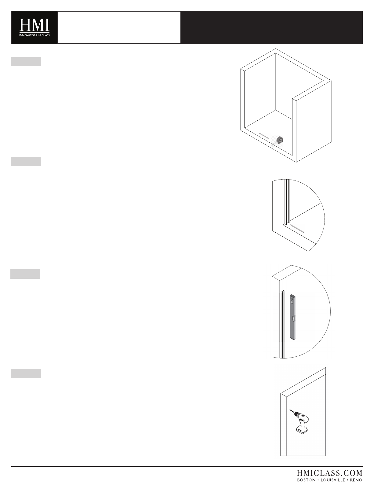
STEP 2
Take the Wall Jamb (A) and line the center of it (indicated by die line) up with
the center line of tub base found in Step 1. The post should be sitting on the
tub or shower base. (See Figure 2)
STEP 3
Make sure that the Wall Jamb (A) is level before marking for holes.
(See Figure 3)
FIGURE 2
FIGURE 3
STEP 1
Determine center line of your shower base by measuring the thickness of the
base and use a pencil to mark the center. Draw this line the entire length of the
base. (See Figure 1)
FIGURE 1
STEP 4
Once the Wall Jamb (A) is level, use a pencil to mark the holes for drilling.
Depending on the support behind the wall, Plastic Anchors (E) may or may
not be required. IF you are unsure, if unsure, use the Plastic Anchors (E) to be
safe. If using an anchor, use 1/4” drill bits to drill holes on the specied marks.
If wooden support is present and no anchor is required, use 3/16” drill bits to
drill holes on specied marks. (See Figure 4)
NOTE:You may need several drill bits when drilling through certain types of
tile or marble. Keep your drill bit cool by spraying with water throughout the
drilling process.
FIGURE 4
V5_21_26
Figure 1
Figure 2
Figure 1
Figure 2
INSTALLATION INSTRUCTIONS
FIGURE 5
TRU-FIT
DOOR & PANEL
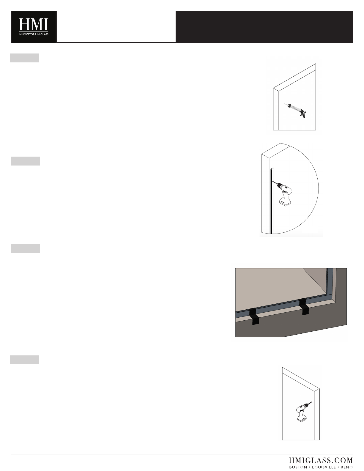
STEP 6
Set the Wall Jamb (A) in place and make sure holes line up. Using six
#10 x 2” Wall Jamb Screws (F) provided, attach Wall Jamb (A) to wall.
(See Figure 6)
NOTE: Two extra screws (F) are provided in case of installation issues.
STEP 7
Now that you have the Wall Jamb (A) mounted, it is time to mount the
panel Wall Channel (C) and Curb Channel (D). You should have two differ-
ent length pieces of the channel (ZSS 4504), the shorter one is the bottom
channel or Curb Channel (D), the longer is the Wall Channel (C). Take the
Curb Channel (D) and place on your “centerline” of your base and make
sure it is all the way against the wall. (See Figure 7)
Use your masking tape to secure the Curb Channel (D) to your base. DO
NOT SUE SILICONE OR SCREWS YET, ONLY TAPE. (See Figure 7)
STEP 8
Place Wall Channel (C) on top of Curb Channel (D) and “centerline”
up wall. Once the Wall Channel (C) is plumb, use a pencil to mark the
holes for drilling. Depending on the support behind the wall, Plastic
Anchors for Channels (J) may or may not be required. If you are unsure,
use the Plastic Anchors for Channels (J) to be safe. If using an anchor,
use 3/16” drill bits to drill holes on the specied marks. If wooden sup-
port is present and no anchor is required, use 1/8” drill bits to drill holes
on specied marks (See Figure 8)
STEP 5
Put a small amount of silicone in each hole drilled. Place Plastic
Anchors (E), if needed, in holes and gently tap with a hammer. Be
sure not to hit the tile. (see Figure 5)
FIGURE 7
FIGURE 8
FIGURE 6
V5_21_26
INSTALLATION INSTRUCTIONS
TRU-FIT
DOOR & PANEL
FIGURE 9
FIGURE 10
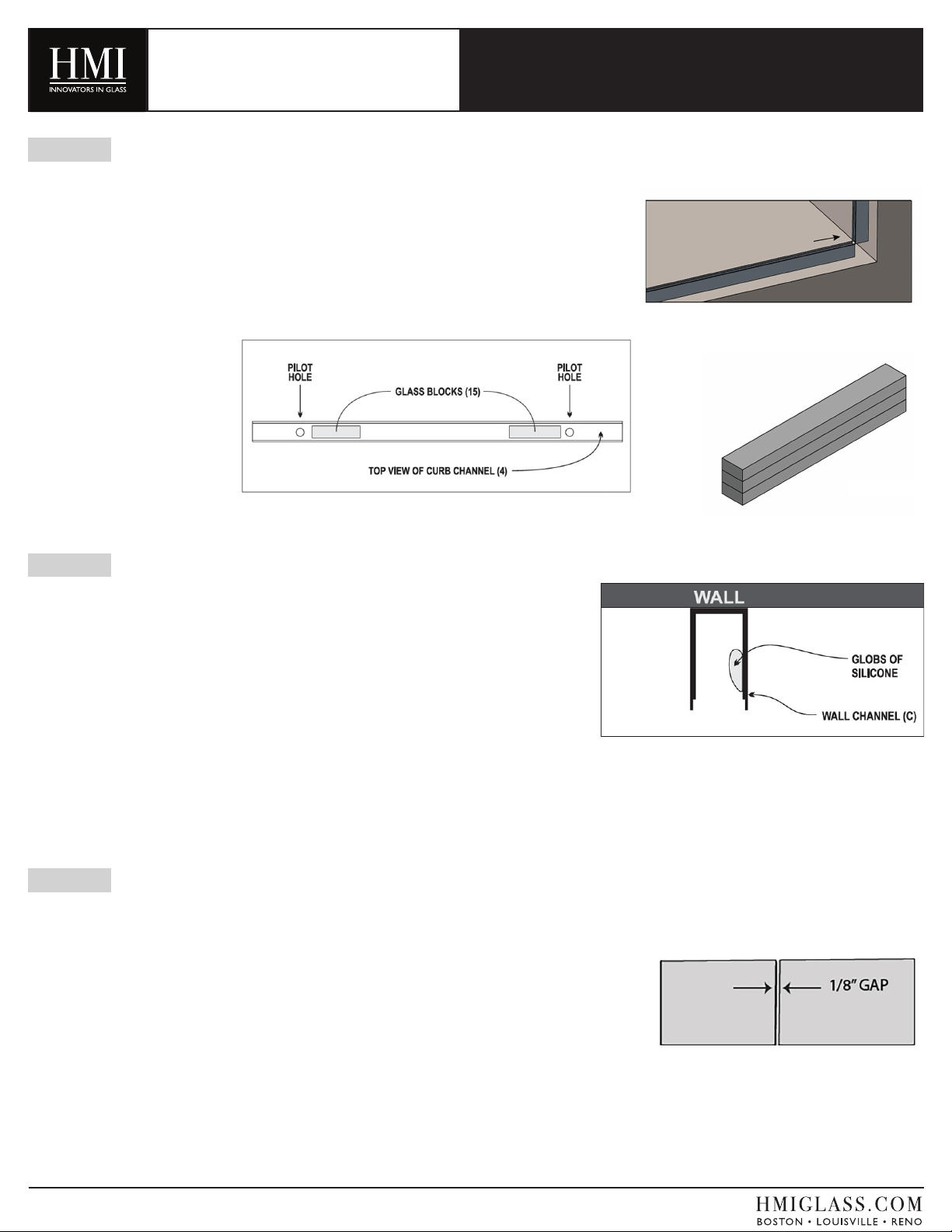
STEP 10
Once Wall Channel (C) is attached, remove tape from Curb Channel
(D) and carefully slide directly out from under Wall Channel (C)
(See Figure 10)
STEP 11
Place Glass Blocks (Q) on base to protect edge of glass
panel while adjusting for size (See Figure 11B). Set Glass
Panel (P) on blocks and gently slide into Wall Channel (C).
Make sure panel is as far in to the Wall Channel (C) as pos-
sible. THE PURPOSE OF THIS STEP IS FOR SPAC-
ING ONLY. PANEL WILL BE REMOVED AGAIN, SO
DO NOT PERMANENTLY ATTACH. Using several
pieces of tape, inside and outside, secure Glass Panel (P) to
wall for the time being. (See Figure 11A)
STEP 9
Put a small amount of silicone in each hole drilled. Place Plastic An-
chors for Channels (J), if needed, in holes gently tap with hammer until
anchor is ush. It might be necessary to use a razor knife to cut the
lip of the anchor off so it is completely ush with the wall. Be sure
not to hit the tile.
(See Figure 9)
Set Wall Channel (C) in place and make sure holes line up. Using #8
x 2” Wall Channel Screws (K) provided, attach Wall Channel (C) to
wall.
FIGURE 11A
FIGURE 11B
FIGURE 12
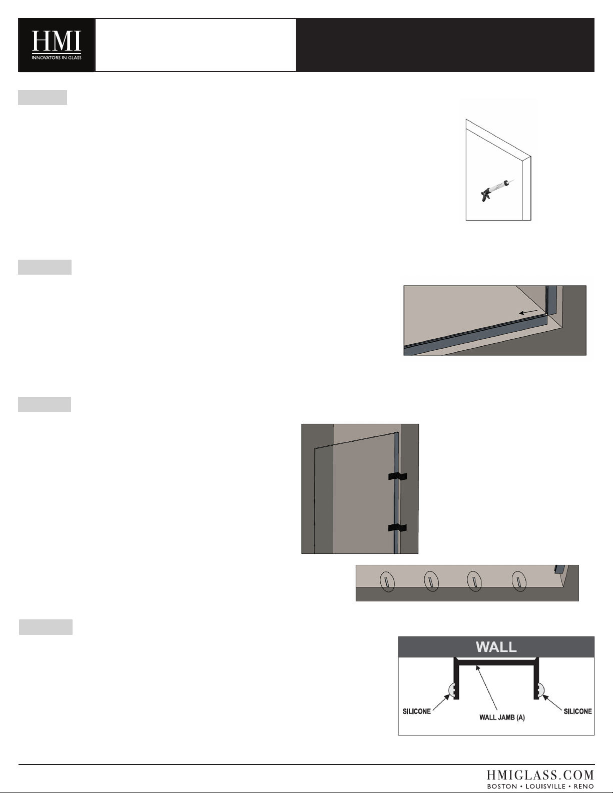
STEP 12
With all six Wall Jamb Screws (H) securely in place, apply bead of
silicone to the outside ribbed edge of Wall Jamb (A) running the entire
length of both sides. (See Figure 12)
V5_21_26

INSTALLATION INSTRUCTIONS
TRU-FIT
DOOR & PANEL
FIGURE 13
STEP 13
Set Wood Block on center of base for spacing and safety. Set the Glass
Door (O) on top of Wood Block (U) and position Hinge Jamb (B) to go
over the Wall Jamb (A). USING TWO PEOPLE (1 PERSON INSIDE,1
PERSON OUTSIDE), slide Hinge Jamb (B) over Wall Jamb (A) carefully
until fully compressed. (See Figure 13) Wood Block should still be under
the Glass Door (O).
ONCE COMPLETED, DO NOT LEAVE DOOR UNATTENDED,
IT COULD STILL FALL!
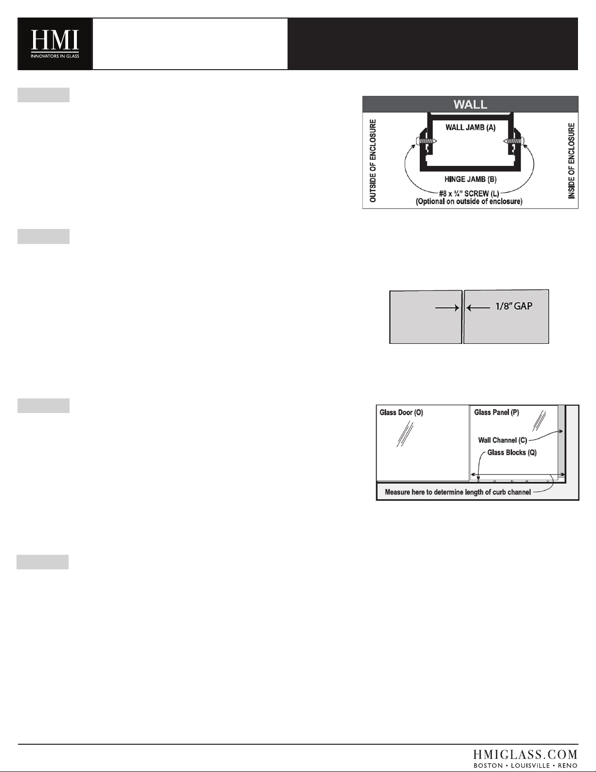
STEP 14
Note that the Glass Door (O) and Glass Panel (P) are setting in
place, while one person steadies the door the other can adjust
both pieces of glass so that you have about 1/8” gap between glass
panels. (See Figure 14) (1/8” is recommended to reduce leakage,
but can be larger if desired). It is ideal to adjust a little in both
door and panel instead of pulling all the adjustment out of one or
the other (depending on your size, you might have to fully adjust
both to ensure proper t). Make sure that the 1/8” gap is uniform
the entire length of the door. Make sure the door is level before
drilling holes. (See Figure 14)
FIGURE 14
ADJUSTMENTS
FIGURE 15
STEP 15
Once adjusted, take a 1/8” drill bit and place in pre-drilled holes on
Hinge Jamb (B). Drill three pilot holes through the Wall Jamb (A).
(See Figure 15)
V5_21_26
INSTALLATION INSTRUCTIONS
TRU-FIT
DOOR & PANEL
STEP 16
Install three #8 x 3/4” Self Tapping Screws (L) into the pilot holes
drilled. (See Figure 16)
FIGURE 16
STEP 17
Now that the Glass Door (O) is secure, double check you have an
1/8” gap between door glass and panel glass. Make any necessary
changes to the Glass Panel (P). (See Figure 17)
FIGURE 17
STEP 18
With the Glass Panel (P) in place, measure from wall to edge of
panel glass. This measurement will be the length you need to cut
your Curb Channel (D). (See Figure 18)
FIGURE 18
STEP 19
Using a pencil, mark your measurement on your Curb Channel (D).
Proceed to cut the Curb Channel (D).
V5_21_26
INSTALLATION INSTRUCTIONS
TRU-FIT
DOOR & PANEL
FIGURE 20A
STEP 20
With door in the open position, carefully remove the Glass Panel (P) and
Glass Blocks (Q) and drill pilot holes in curb channel as shown in Figure 20
A. Replace the Curb Channel (D) under the Wall Channel (C). Use a pencil
to mark for pilot holes and remove channel for drilling. Using a 3/16” drill bit,
drill two pilot holes through the Curb Channel (D) into base (See Figure 20A).
Space both holes per Figure 20A. PUT A DROP OF SILICONE in holes, re-
place Curb Channel (D) and secure with #8 x 2” Screws (K). (See Figure 20B)
FIGURE 20B
FIGURE 21A
FIGURE 21B
STEP 21
Place two stacks of three Glass Blocks (Q) inside the Curb Channel (D) per
Figure 20A. NOTE: DO NOT SET ON SCREW HEADS. These glass
blocks will be used not only to cushion and protect panel from screw heads
but to also adjust the height of the panel to match the door. You can remove
glass blocks to lower panel, cut glass blocks in half and stack more than three
to raise the panel. (See Figure 21A). When ready to install glass, put four or
ve globs of silicone on the inside of the wall channel (See gure 21B). Set
Glass Panel (P) in the Curb Channel (D) on Glass Blocks (Q) and gently push
into Wall Channel (C) until glass is event Curb Channel (D).
FIGURE 22
STEP 22
Double-check that the height of the Glass Panel (P) is even with the Glass
Door (O) and 1/8” gap between pieces of glass is uniform. (See Figure 22)
V5_21_26

INSTALLATION INSTRUCTIONS
TRU-FIT
DOOR & PANEL
FIGURE 23
STEP 23
Silicone the Glass Panel (P) in place by applying an even bead inside troughs
on both sides of Wall Channel (C) and Curb Channel (D) as well as where the
wall channel and curb channel meet the wall and base. (See Figure 23)
Clean off any excess silicone.
FIGURE 24
STEP 24
We have supplied two extra #8 x 3/4” Self Tapping Screws (L).
WE RECOMMEND PUTTING THESE ON THE OUTSIDE OF THE
UNIT FOR EXTRA SUPPORT.
These are not necessary, but highly suggested to eliminate any movement
during usage. Using a 1/8” drill bit, drill two pilot holes through both the Hinge
Jamb (B) and the Wall Jamb (A) centered vertically with the Door Hinges (E).
(See Figure 24)
FIGURE 25
STEP 25
Apply a bead of silicone where the Wall Jamb (A) meets the wall on BOTH
sides. (See Figure 25)
V5_21_26

INSTALLATION INSTRUCTIONS
TRU-FIT
DOOR & PANEL
STEP 26
The Adjustable Post Cap (N) covers the exposed top of the Wall Jamb (A)
and Hinge Jamb (B). Set the cap in place BACKWARDS (only to mark it for
cutting) with the legs going in Hinge Jamb (B) (See Figure 26A) and mark for
cutting (See Figure 26B).
MAKE SURE CAP IS TOUCHING BACK WALL BEFORE MARKING.
Cut cap on mark using scissors. (See Figure 26C)
Place drop of silicone on the outside of both legs. (See Figure 26D)
Turn the Adjustable Post Cap (N) around and install with the legs going into
the Wall Jamb (A). (See Figure 26E)
FIGURE 26A
FIGURE 26B
FIGURE 26C
FIGURE 26D
FIGURE 26E
V5_21_26

INSTALLATION INSTRUCTIONS
FIGURE 27
STEP 27
To attach the Back-to-Back C-Pull (F), rst loosen set screws with an allen
wrench and take the pull apart. (See Figure 27)
NOTE:The pull is mounted so that there is no metal touching the glass. The
clear plastic washers go on either side of the glass between the pull and the
glass.
TRU-FIT
DOOR & PANEL
FIGURE 28A
STEP 28
Place handle through holes in the Door Glass (O). Make sure that the clear
washers are touching the glass. Gently tighten handle screws so that handle
is snug on glass. DO NOT OVER-TIGHTEN THE SCREWS with the allen
wrenches supplied with the pull. Over-tightening can crack the washers. (See
Figure 28A)
Place other side of handle on studs (See Figure 28B) with set screws facing
down and tighten using allen key provided. (See Figure 28C and 28D)
FIGURE 28B FIGURE 28C FIGURE 28D
V5_21_26
INSTALLATION INSTRUCTIONS
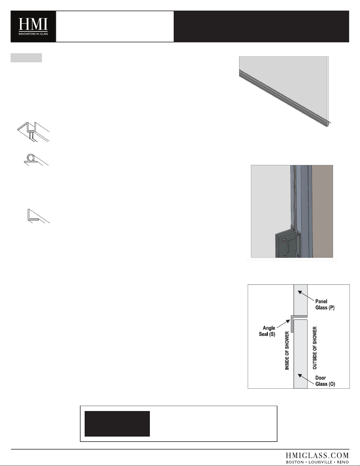
STEP 29
There are three different polycarbonates provided. All are
OPTIONAL and serve to help prevent water from escaping
shower.
NOTE: If using the optional polycarbonates, for the best adhesion,
clean glass or tile with alcohol before application.
ZV 952 Bottom Sweep (L) - This is attached by pressing it on
bottom of door while door is open. Wood block should have
been removed. (See Figure 29A)
ZV SDTB Bulb Seal (N) - This is to be placed on hinge edges
of glass. You will need to cut into 3 pieces that will t the small
areas from top hinge to top of door, bottom hinge to bottom
of door and the large area between hinges. Remove red cover-
ing to expose adhesive and apply to edge of glass.
(See Figure 29B)
ZV Angle Seal (M) - This is to be placed on handle side of
door, DIRECTLY to the Panel Glass (P) (make sure glass is
clean and dry before application). (See Figure 29C)
CAUTION: By using this angle seal, your door will no
longer be able to swing both in and out.
(See Figure 29C)
TRU-FIT
DOOR & PANEL
FIGURE 29A
FIGURE 29B
FIGURE 29C
IMPORTANT
NOTE
DOOR SHOULD NOT BE USED FOR 72 HOURS
IN ORDER TO LET SILICONE CURE PROPERLY!
V5_21_26

INSTALLATION INSTRUCTIONS
TRU-FIT
DOOR & PANEL
INSTALLATION:
If, while preparing to attach the Hinge Jamb (B) to the Wall
Jamb (A), you are unable to get a consistent 1/8” gap between
the Door Glass (O) and Panel Glass (P) without revealing the
groove lines on the Wall Jamb (A), either your walls may be
seriously out of plumb or your selected unit might not be the
right size for your conditions. Double check your wall condi-
tions and measurements.
OPERATION:
If you have not installed the #8 x 3/4” Set Screws (L) on the
outside of the enclosure securing the Hinge Jamb (B) to the
Wall Jamb (A), and you are noticing movement of the Hinge
Jamb (B) during normal operation, we strongly suggest you go
to Step 24 and install the Set Screws (L) on the outside of the
enclosure.
TROUBLESHOOTING
To make a claim under the provisions of this warranty, please
contact your local HMI Shower Enclosure dealer. They
should be able to solve any problem you might have.
If your dealer cannot solve your problem, they will contact
your local HMI Shower Enclosure distribution center.
If you are unable to obtain warranty service through your
local HMI Shower Enclosure distribution center, you can
contact us at:
HMI
4795 Shepherdsville Road
Louisville, KY 40218 USA
email: [email protected]
Please include all relevant information regarding your claim:
• The model which was installed.
• The name and address of the installer..
• The installation address.
• A complete description of the problem.
• A photocopy of your invoice/receipts for the product
installed.
Under no circumstances should HMI Shower Enclosures
products be returned to your dealer, distributor, or the HMI
Shower Enclosures without a written Return Merchandise
Authorization (RMA).
WARRANTY CLAIMS
V5_21_26
Table of contents
Popular Bathroom Fixture manuals by other brands

Croydex
Croydex AD179441 Fixing and care instructions

MAAX
MAAX 100589 installation instructions

Pfister
Pfister Penn LF-048-PE Quick installation guide

Signature Hardware
Signature Hardware St.Martin 948599 Installation

Bradley
Bradley S19-280D installation guide

BELLOSTA
BELLOSTA Zehn 7505/N4/A Installation instruction


Sanela
Sanela SLU 92PB Instructions for use

MGS
MGS CB437 manual

Galvin Specialised
Galvin Specialised Safe-Cell 50117C Installation guidelines

Axor
Axor 250 1jet 35284 7 Series Instructions for use/assembly instructions

Hans Grohe
Hans Grohe ECO Crometta Vario 26332407 Instructions for use/assembly instructions

BEMIS
BEMIS bioBidet BB-2000 user manual