DEVA VSNSEQT01 User manual

DTC INST 158 – 18.4.11 ISSUE 2
VSNSEQT01
VISION EXPOSED
VISION EXPOSED VISION EXPOSED
VISION EXPOSED
THERMOSTATIC SEQUENTIAL
THERMOSTATIC SEQUENTIAL THERMOSTATIC SEQUENTIAL
THERMOSTATIC SEQUENTIAL
SHOWER
SHOWERSHOWER
SHOWER
Guarantee
GuaranteeGuarantee
Guarantee
Your roduct comes with a 5 year guarantee; this includes
2 years arts and labour, with the following 3 years arts only,
roof of urchase will be required.
This guarantee is invalid if the roduct is misused, incorrectly
installed, maintained or cleaned.
Installation
Installations should be carried out by a com etent installer,
who must after com letion, check for leaks, from both the
roduct and i e work.
All installations must be carried out in com liance with Water
Bye Law Regulations, for further details contact your Local
Water Authority.
The roduct must be installed and used in such a way as not to
cause water damage, therefore water from the roduct must be
suitably directed and/or retained.
Cleaning
This roduct should be maintained using a clean dam cloth, do
not use abrasive agents or materials on the roduct surface.
For technical, installation, servicing advice and/or s are arts
lease call:
CUSTOMER CARE LINE
0800 1951602
Deva reserves the right to change or im rove the roducts described in any of its
ublications

DTC INST 158 – 18.4.11 ISSUE 2
Contents
ContentsContents
Contents
O erating S ecification
General Details
Technical Data
Installation
Calibration
Cartridge Change and Cleaning
Elbow Filter Cleaning
Dimensions
Guarantee
Dimensions
DimensionsDimensions
Dimensions
DTC INST 158 – 18.4.11 ISSUE 2
O erating S ecification
O erating S ecificationO erating S ecification
O erating S ecification
High Pressure Low Pressure
Maximum Static Pressure – Bar 10 10
Flow Pressure, Hot & Cold - Bar 0.5 to 5 0.2 to 1
Hot Su ly Tem erature - °C 52 to 65 52 to 65
Cold Su ly Tem erature - °C 5 to 20 5 to 20
Tem erature Differential -°C 10 10
NOTE: Valves o erating outside these conditions cannot be guaranteed by the
Scheme to o erate as Ty e 3 valves.
Hot and cold su ly ressures should be ke t balanced in order to obtain maximum
efficiency.
The valves designation of use is for High Pressure Shower (HP-S) BS EN 1111 and
the recommended mixed water outlet for showers at oint of discharge is 41°C
When ressures exceed 5 bar, a ressure reducing valve must be fitted (not
su lied) before the valve assembly.
If a water su ly is fed by gravity then the su ly ressure should be verified to
ensure the conditions of use are a ro riate for the valve.
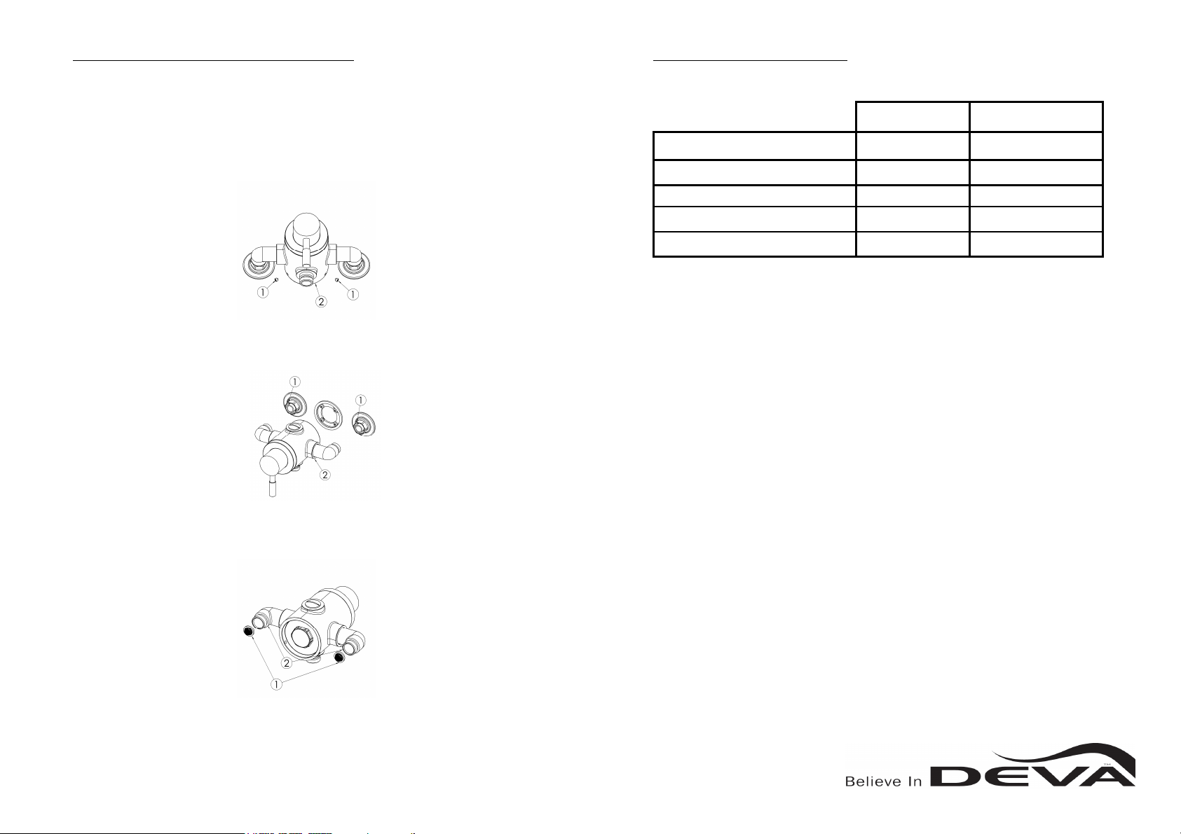
Cleaning or re lacing elbow filters
Cleaning or re lacing elbow filtersCleaning or re lacing elbow filters
Cleaning or re lacing elbow filters
Through years of use, im urities and lime scale could build u on the filters in the elbows
which could affect the erformance of the roduct, you should then remove the filters and
clean.
To do this, first turn off the water su ly to the valve, then remove the grub screws (1) from
the valve body (2) using the allen key rovided.
Disconnect the valve (2) from the nuts (1) and remove valve, ensure that you take a firm
hold of the valve body to revent it from falling into the shower/bath.
Remove the filters (1) from inside the elbows (2) and carry out maintenance, to clean hold
under running water.

DTC INST 158 – 18.4.11 ISSUE 2
General Details
General DetailsGeneral Details
General Details
The urchased roduct is a thermostatic sequential ex osed shower valve.
The shower has a single lever which allows both control of tem erature and flow.
The cold water is obtained by turning the lever from the OFF osition anti-clockwise.
(NOTE: The tem erature of the cold water de ends on the system and the re-set
tem erature of the shower).
By turning the lever both flow and tem erature will increase.
The maximum tem erature has been re-set under factory conditions at a rox 45°c,
this can be adjusted by following the instructions shown in the section headed
“CALIBRATION”
Subject to correct installation, this mixer is suitable for any water system, in case of
instantaneous heaters, hot water flow must meet at last the minimum flow required by
the heater.
Technical D
Technical DTechnical D
Technical Data
ataata
ata
The water su lies are connected to the mixer via two elbows, which include
com ression nuts and olives to suit 15mm su ly i es.
The tem erature setting has been carried out under factory conditions and in
accordance with BS EN1111.
The shower will be received with the outlet to the bottom and the hot inlet (red sticker)
to the left), if you require a to outlet, do not sim ly turn the valve over, you must
change the location of the blanking lug and outlet.
Remove the blanking lug using a wide blade screw driver and remove the outlet using
a 12mm allen key.
Once removed swa the lug and outlet and re-fit and tighten fully
.
Cleaning or re lacing cartridge
Cleaning or re lacing cartridgeCleaning or re lacing cartridge
Cleaning or re lacing cartridge
Using a 30mm s anner unscrew the cartridge and flange (1) from the valve (2) by
turning anti-clockwise.
To clean the filters (1) of cartridge (2) kee arts 1,2 & 3 together and run under
warm water or soak in vinegar or de-scaling agent, then rinser thoroughly and
re lace.
To re lace cartridge, unscrew lower section of (2) from flange (3) by turning
anti-clockwise.

DTC INST 158 – 18.4.11 ISSUE 2
Installation (Always flu
Installation (Always fluInstallation (Always flu
Installation (Always flu
sh the system rior to installation)
sh the system rior to installation)sh the system rior to installation)
sh the system rior to installation)
Pre are the su ly i es for the mixer at 150mm centres and allow the i e ends to
extend to a minimum of 10mm from the finished surface to allow tightening to the
com ression elbows.
Position the tem late onto the wall over the i e ends and drill the holes using a 6mm
drill bit
Remove the tem late and insert wall lugs (1) into the drilled holes.
Cleaning or re lacing cartridge
Cleaning or re lacing cartridgeCleaning or re lacing cartridge
Cleaning or re lacing cartridge
Through years of use, im urities and lime scale could build u on filter and
cartridge which could affect the erformance of the roduct, you should then
remove the cartridge and clean.
Firstly turn off the water su ly to the valve, then remove the lever arm (2) and
grub screw (1) from head section (3)
Remove the grub screw (1) using the allen key rovided from inside the head
section (2) and then ull head section from valve.
Remove the tem erature sto ring (1), it maybe beneficial to mark the sto ring
and valve s indle to allow re-alignment after maintenance, then remove the valve
chrome ring (2) by turning anti-clockwise.

DTC INST 158 – 18.4.11 ISSUE 2
Calibration
CalibrationCalibration
Calibration
Once installed the tem erature settings can be adjusted, but note this roduct is a
sequential mixer and therefore if the maximum outlet tem erature is increased the
minimum tem erature will also increase.
Turn the shower to fully hot and then turn off the water su ly to the valve.
Remove the lever arm (2) and grub screw (1) from head section (3)
Remove grub screw (1) from inside the head section (2) , using the allen key rovided.
You must then slightly loosen the nut (1) using a 13mm s anner, insert the allen key
inside the nut and turn the grub screw, turn it anti-clockwise to increase the
tem erature.
O
nce the desired tem erature is reached, carry out this
instruction in reverse to re-assemble
Installation
InstallationInstallation
Installation
Position the mounting bracket (1) over the drilled holes and secure to wall using
screws rovided (2)
Next lace the trim seals (1), trim lates (2), com ression nuts (3) and olives (4) over
i e ends.
Before installing the valve, if there is a variation in ressure between hot and cold, the
su lied regulators can be used in the elbow (3) to reduce the higher ressure, to do
this, insert the regulator (2) into the elbow, followed by the brass retaining ring (1)

DTC INST 158 – 18.4.11 ISSUE 2
Installation
InstallationInstallation
Installation
Screw the elbows (1) into the shower valve body and align so they oint to the rear.
Push the shower valve (1) onto the mounting bracket secured to the wall, then ush the
elbows over the i e ends and connect nuts (2) to shower valve and fully tighten nuts using
a s anner.
Secure the valve (2) using the grub screws (1) rovided into the holes on the underside
Installation
InstallationInstallation
Installation
Remove the lastic rotection cover (1) from the valve.
Insert long grub screw (1) into head section (3) using allen key su lied, then screw
on lever arm (2) .
Check that tem erature is set at 41°C before shower is used
Your installation is now com lete and the water su ly can now be turned on, the
com lete installation must now be checked for leaks.
Table of contents
Other DEVA Bathroom Fixture manuals


