HMS Networks Anybus Wireless Bolt User manual

Anybus®Wireless Bolt™
USER MANUAL
SCM-1202-007 2.8 en-US ENGLISH

Important User Information
Disclaimer
The information in this document is for informational purposes only. Please inform HMS Industrial Networks of any
inaccuracies or omissions found in this document. HMS Industrial Networks disclaims any responsibility or liability
for any errors that may appear in this document.
HMS Industrial Networks reserves the right to modify its products in line with its policy of continuous product
development. The information in this document shall therefore not be construed as a commitment on the part of
HMS Industrial Networks and is subject to change without notice. HMS Industrial Networks makes no commitment
to update or keep current the information in this document.
The data, examples and illustrations found in this document are included for illustrative purposes and are only
intended to help improve understanding of the functionality and handling of the product. In view of the wide range
of possible applications of the product, and because of the many variables and requirements associated with any
particular implementation, HMS Industrial Networks cannot assume responsibility or liability for actual use based on
the data, examples or illustrations included in this document nor for any damages incurred during installation of the
product. Those responsible for the use of the product must acquire sufficient knowledge in order to ensure that the
product is used correctly in their specific application and that the application meets all performance and safety
requirements including any applicable laws, regulations, codes and standards. Further, HMS Industrial Networks will
under no circumstances assume liability or responsibility for any problems that may arise as a result from the use of
undocumented features or functional side effects found outside the documented scope of the product. The effects
caused by any direct or indirect use of such aspects of the product are undefined and may include e.g. compatibility
issues and stability issues.
Anybus®Wireless Bolt™User Manual SCM-1202-007 2.8 en-US

Anybus®Wireless Bolt™User Manual SCM-1202-007 2.8 en-US
Table of Contents Page
1 Preface ................................................................................................................................. 3
1.1 About This Document .......................................................................................................3
1.2 Document Conventions.....................................................................................................3
1.3 Trademarks.....................................................................................................................3
2 Safety ................................................................................................................................... 4
2.1 General Safety Instructions................................................................................................4
2.2 Intended Use...................................................................................................................4
2.3 Type Identification ...........................................................................................................4
3 Installation........................................................................................................................... 5
3.1 General Information .........................................................................................................5
3.2 Limitations......................................................................................................................5
3.3 Mechanical Installation .....................................................................................................6
3.4 Connector.......................................................................................................................7
3.5 Ethernet Cabling ..............................................................................................................8
3.6 Digital Input ....................................................................................................................8
3.7 RESET Button ..................................................................................................................9
4 Configuration..................................................................................................................... 10
4.1 General ........................................................................................................................ 10
4.2 Web Interface ............................................................................................................... 11
4.3 Factory Restore ............................................................................................................. 26
A Configuration Examples .................................................................................................... 27
A.1 Ethernet Bridge via WLAN or Bluetooth®(Easy Config) .......................................................... 27
A.2 PROFINET networking via Bluetooth®................................................................................. 28
A.3 EtherNet/IP™Networking via Bluetooth®............................................................................. 29
A.4 Ethernet network to existing WLAN................................................................................... 30
A.5 Adding single Ethernet node to WLAN ............................................................................... 31
A.6 Accessing PLC via WLAN from Handheld Device................................................................... 32
B Wireless Technology Basics .............................................................................................. 34
C Radio Antenna Patterns.................................................................................................... 35
C.1 Azimuth (Horizontal) View ............................................................................................... 35
C.2 Vertical Views................................................................................................................ 36
C.3 Throughput Diagram....................................................................................................... 37

Anybus®Wireless Bolt™User Manual SCM-1202-007 2.8 en-US
D Technical Data ................................................................................................................... 38
D.1 Hardware Specifications.................................................................................................. 38
D.2 Communication ............................................................................................................. 39

Preface 3 (40)
1 Preface
1.1 About This Document
This manual describes how to install and configure Anybus Wireless Bolt.
For additional documentation and software downloads, FAQs, troubleshooting guides and
technical support, please visit www.anybus.com/support.
1.2 Document Conventions
Numbered lists indicate tasks that should be carried out in sequence:
1. First do this
2. Then do this
Bulleted lists are used for:
• Tasks that can be carried out in any order
• Itemized information
►An action
→ and a result
User interaction elements (buttons etc.) are indicated with bold text.
Program code and script examples
Cross-reference within this document: Document Conventions, p. 3
External link (URL): www.hms-networks.com
WARNING
Instruction that must be followed to avoid a risk of death or serious injury.
Caution
Instruction that must be followed to avoid a risk of personal injury.
Instruction that must be followed to avoid a risk of reduced functionality and/or damage
to the equipment, or to avoid a network security risk.
Additional information which may facilitate installation and/or operation.
1.3 Trademarks
Anybus®is a registered trademark and Wireless Bolt™is a trademark of HMS Industrial Networks
AB. All other trademarks mentioned in this document are the property of their respective
holders.
Anybus®Wireless Bolt™User Manual SCM-1202-007 2.8 en-US

Safety 4 (40)
2 Safety
2.1 General Safety Instructions
Caution
This equipment emits RF energy in the ISM (Industrial, Scientific, Medical) band. Make
sure that all medical devices used in proximity to this equipment meet appropriate
susceptibility specifications for this type of RF energy.
This equipment is recommended for use in both industrial and domestic environments.
For industrial environments it is mandatory to use the functional earth connection to
comply with immunity requirements. For domestic environments the functional earth
must be used if a shielded Ethernet cable is used, in order to meet emission requirements.
This equipment contains parts that can be damaged by electrostatic discharge (ESD). Use
ESD prevention measures to avoid damage.
2.2 Intended Use
The intended use of this equipment is as a communication interface and gateway. The
equipment receives and transmits data on various physical levels and connection types.
If this equipment is used in a manner not specified by the manufacturer, the protection provided
by the equipment may be impaired.
2.3 Type Identification
The type name consists of a type prefix followed by two designators for interface configuration
and functionality.
Prefix AWB2 Anybus Wireless Bolt
Interface configuration A
B
Interface 18-pin socket
Interface RJ45 and 3-pin power socket
Functionality A
B
C
Ethernet
Ethernet and RS232/485
Ethernet and CAN
Example: AWB2AA = Anybus Wireless Bolt with18-pin plug connector and Ethernet networking
only.
Anybus®Wireless Bolt™User Manual SCM-1202-007 2.8 en-US

Installation 5 (40)
3 Installation
3.1 General Information
Make sure that you have all the necessary information about the capabilities and restrictions of
your local network environment before installation.
The characteristics of the internal antenna should be considered when choosing the placement
and orientation of the unit.
For optimal reception, wireless devices require a zone between them clear of objects that could
otherwise obstruct or reflect the signal. A minimum distance of 50 cm between the devices
should also be observed to avoid interference.
See also Wireless Technology Basics, p. 34.
3.2 Limitations
Bluetooth PAN (Personal Area Network) may not work with some devices due to different
implementations of Bluetooth by different manufacturers.
WLAN 5 GHz cannot be used at the same time as WLAN 2.4 GHz or Bluetooth.
Anybus®Wireless Bolt™User Manual SCM-1202-007 2.8 en-US

Installation 6 (40)
3.3 Mechanical Installation
The device is intended to be mounted through an M50 (50.5 mm) hole using the included sealing
ring and nut.
The top mounting surface (in contact with the sealing) must be flat with a finish equivalent to
Ra 3.2 or finer and cleaned and free from oils and greases.
Tightening torque: 5 Nm ±10 %.
Make sure that the sealing ring is correctly placed in the circular groove in the top part of
the housing before tightening the nut.
Always hold the BOTTOM part of the unit when untightening the nut, not the top part
(the cap).
Fig. 1 Installation drawing
All measurements are in mm.
Anybus®Wireless Bolt™User Manual SCM-1202-007 2.8 en-US

Installation 7 (40)
3.4 Connector
The 18-pin connector is common for all models of the Anybus Wireless Bolt. Some pins may have
a different function depending on model. Unused pins should not be connected.
Fig. 2 Connector
The location of the RESET button can be used as a reference for the pin numbering when the
connector is attached to the Wireless Bolt. Pin 1 will be the pin closest to the button.
Pin Name Description
1 VIN Power + (9–30 V)
2 GND Power Ground
3 DI Digital input + (9–30 V)
4DI_GND Digital input ground
5ETN_RD+ Ethernet receive + (white/orange)
6ETN_RD- Ethernet receive - (orange)
7ETN_TD- Ethernet transmit - (green)
8ETN_TD+ Ethernet transmit + (white/green)
9RS485_B RS-485 B Line
10 FE/Shield Ethernet:
Serial:
Functional Earth
Functional Earth and Shield
11 RS232_TXD RS-232 Transmit
12 RS485_A/RS232_RXD RS-485 A Line / RS-232 Receive
13 RS232_RTS RS-232 Request To Send
Not supported for Wireless Bolt.
14 RS232_CTS RS-232 Clear To Send
Not supported for Wireless Bolt.
15 ISO_5V Isolated 5 V for serial interface
16 RS232_GND/RS485_GND Isolated Ground for serial interface
17 CAN_L CAN Low
18 CAN_H CAN High
Note:
• The Ethernet wire colors refer to the T568A standard.
• If using a shielded Ethernet cable the shield must be unconnected.
• RS-232 and RS-485 cannot be used at the same time.
• Use termination for RS-485 and CAN when required.
Anybus®Wireless Bolt™User Manual SCM-1202-007 2.8 en-US

Installation 8 (40)
3.5 Ethernet Cabling
To make an Ethernet connector cable for Anybus Wireless Bolt:
Fig. 3
1. Cut off one of the connectors on a standard Cat5e or Cat6 Ethernet cable.
2. Strip off about 40 mm (1½ inch) of the cable jacket and untwist the orange, orange/white,
green and green/white wires. The other wires will not be used.
3. Strip off about 7 mm (¼ inch) of the isolation on each wire.
4. Push the pin spring release next to each socket on the connector and insert the correct wire
end according to Connector, p. 7.
Connect the wires from the power supply to the connector in the same way as the Ethernet
wiring. Make sure that polarity is not reversed.
RJ-45 Adapter
An Ethernet adapter with an RJ45 female connector can be ordered as an accessory. Please
contact your sales representative for more information.
3.6 Digital Input
The digital input can be used to control roaming between Bluetooth access points (NAP). For
more information, refer to the AT Reference Guide at www.anybus.com/support.
If voltage is applied to the digital input for more that 10 seconds the unit will be reset to
factory defaults.
Anybus®Wireless Bolt™User Manual SCM-1202-007 2.8 en-US

Installation 9 (40)
3.7 RESET Button
Fig. 4 RESET button
The RESET button is located on the bottom of the unit.
When the unit is powered on, press and hold RESET for >10 seconds and then release it to reset
to the factory default settings.
Recovery Mode
If the web interface cannot be accessed, the unit can be reset by starting in Recovery Mode and
reinstalling the firmware using Anybus Firmware Manager II, which can be downloaded from
www.anybus.com/support.
To enter Recovery Mode, press and hold RESET during startup.
Firmware updates should normally be carried out through the web interface. Recovery
Mode should only be used if the unit is unresponsive and the web interface cannot be
accessed.
Anybus®Wireless Bolt™User Manual SCM-1202-007 2.8 en-US

Configuration 10 (40)
4 Configuration
4.1 General
Anybus Wireless Bolt should normally be configured via the web interface. Parameters can be set
individually or using one of the pre-configured Easy Config modes.
The web interface is accessed by pointing a web browser to the IP address of the Wireless Bolt.
The default address is 192.168.0.99. The computer accessing the web interface must be in the
same IP subnet as the Wireless Bolt.
Fig. 5 Web interface
Advanced configuration can be carried out by issuing AT (modem) commands through the web
interface or over a Telnet or RAW TCP connection to port 8080. See the AT Commands Reference
Guide or the Help page in the web interface for more information.
Anybus®Wireless Bolt™User Manual SCM-1202-007 2.8 en-US
Configuration 11 (40)
4.2 Web Interface
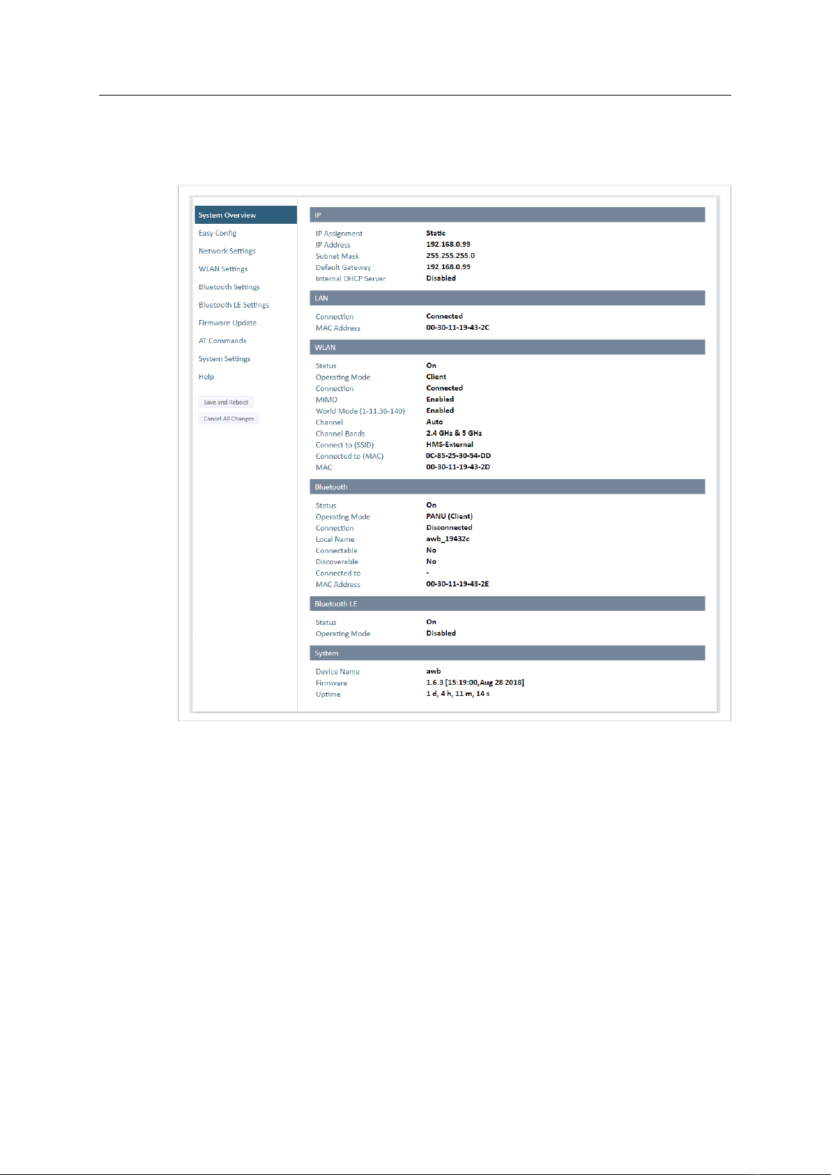
4.2.1 System Overview
Fig. 6 System Overview page
The System Overview page shows the current settings and connection status for the wired and
wireless interfaces. The different parameters are explained in the descriptions of each settings
page in this manual.
The Help page describes AT commands that can be used for advanced configuration.
Save and Reboot This button will be enabled if the unit must be restarted to apply a change.
Cancel All Changes Resets parameter changes that have not been applied.
Anybus®Wireless Bolt™User Manual SCM-1202-007 2.8 en-US
Configuration 12 (40)
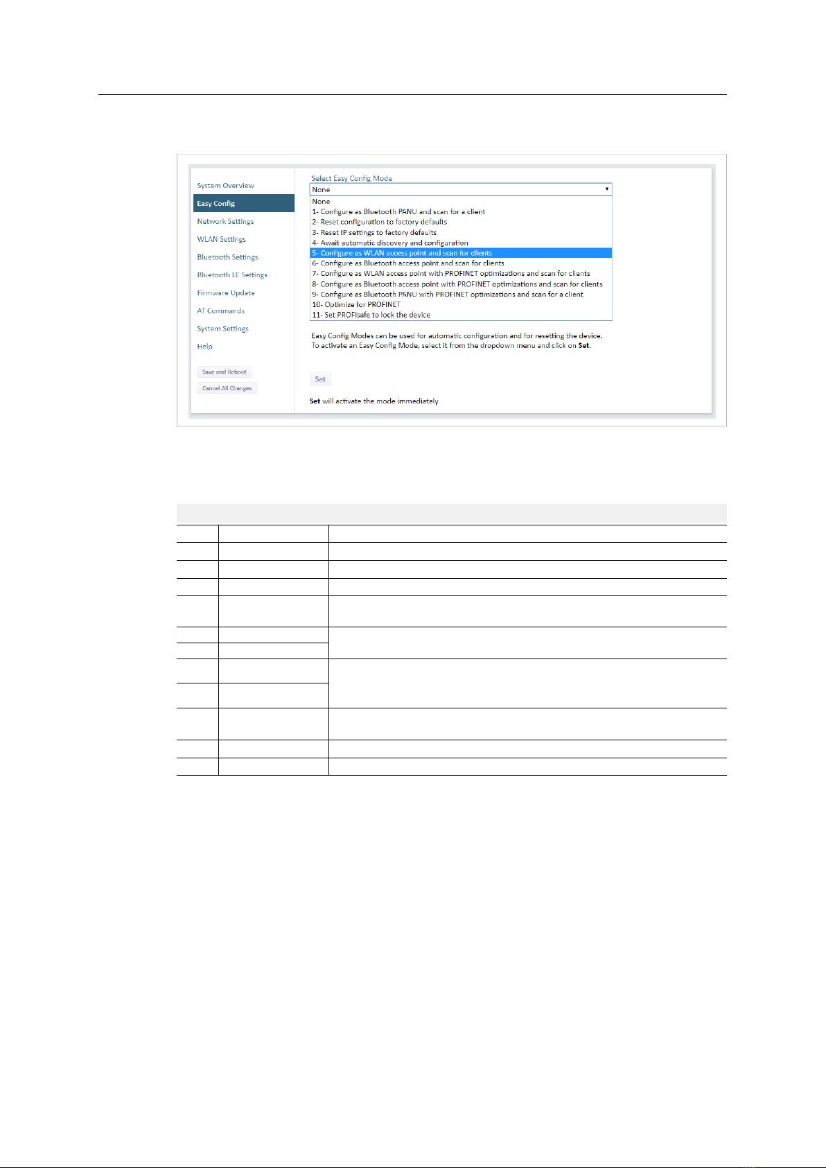
4.2.2 Easy Config
Fig. 7 Easy Config page
To activate an Easy Config mode, select it from the dropdown menu and click on Set. The mode
will be activated immediately.
Easy Config Modes
EC Role Description
1Bluetooth PANU Configure as Bluetooth client and scan for another client (PANU–PANU).
2–Reset configuration to factory defaults.
3–Reset IP settings to factory defaults.
4Client Wait for automatic configuration.
Configure units in mode 4 as clients.
5WLAN AP Configure units in mode 4 as clients.
Restart as access point and connect clients.
6Bluetooth NAP
7WLAN AP Restart as access point and connect clients.
Apply PROFINET optimization to all units.
8Bluetooth NAP
9Bluetooth PANU Configure as Bluetooth client and scan for another client (PANU–PANU).
Apply PROFINET optimization to both units.
10 (any) Apply PROFINET optimization and restart.
11 (any) Enable PROFIsafe mode.
Anybus®Wireless Bolt™User Manual SCM-1202-007 2.8 en-US

Configuration 13 (40)
Notes:
• Mode 1 will scan for units in mode 4. When a unit in mode 4 is detected, the scanning unit
will configure itself as a Bluetooth PANU client, send a connection configuration to the
detected unit, and restart. The detected unit will also restart and attempt to connect to the
first unit as a PANU client.
• Modes 5, 6, 7 and 8 will scan for units in mode 4. The detected units will be reconfigured as
clients and the scanning unit will restart as an access point. The clients will then restart and
connect to the access point.
• Modes 7 and 8 will additionally apply PROFINET optimization to all the units. PROFINET
messages will then have priority over TCP/IP frames.
• Mode 11 locks the unit in PROFIsafe mode where the configuration cannot be changed
without physical access. To cancel this mode the unit must be restored to factory defaults
by pressing and holding the RESET button.
• Modes 10 and 11 will be added to the configuration without changing any other settings.
• Modes 1 and 9 will listen for 40 seconds or until a configuration is established.
• Modes 4 will listen for 120 seconds or until receiving a configuration.
• Modes 5, 6, 7 and 8 will time out after 120 seconds.
Anybus®Wireless Bolt™User Manual SCM-1202-007 2.8 en-US

Configuration 14 (40)
4.2.3 Network Settings
Fig. 8 Network Settings page
IP Assignment Select static or dynamic IP addressing (DHCP)
IP Address Static IP address for the unit
The browser should automatically be redirected to the new address after clicking on
Save and Reboot (not supported by all browsers).
Subnet Mask Subnet mask when using static IP
Default Gateway Default gateway when using static IP
Internal DHCP Server Disabled: No internal DHCP functionality
DHCP Relay Enabled: The unit can receive a DHCP request on one interface and resend
it to a DHCP server located on one of the other interfaces.
Only a single DHCP server can be active for all the connected interfaces.
If WLAN is used, the forwarding mode must be set to Layer 3 IP Forward.
DHCP Server Enabled: Activates an internal DHCP server. This option is only available
when IP Assignment is set to Static.
Do not enable this option if there is already a DHCP server on the network!
Start Address (Y) The internal DHCP server will assign up to 7 IP addresses starting from X.X.X.Y, where X
is taken from the current static IP address setting, and Yis the value in Start Address.
Already allocated addresses will be skipped, including the address of the unit itself. The
subnet mask setting will be ignored.
Examples:
IP Address: 192.168.0.99, Start Address: 101
DHCP range = 192.168.0.101 – 192.168.0.107
IP Address: 192.168.0.103, Start Address: 101
DHCP range = 192.168.0.101 – 192.168.0.108
7 addresses are allocated but the address of the unit is skipped.
Anybus®Wireless Bolt™User Manual SCM-1202-007 2.8 en-US

Configuration 15 (40)
4.2.4 WLAN Settings - Client
Fig. 9 WLAN Settings - Client
Enable Enable/disable the WLAN interface.
Operating Mode Choose operation as WLAN Client or Access Point. If Access Point is selected, additional
settings will be available.
Channel Bands Choose to scan only the 2.4 GHz or 5 GHz channel band, or both (default).
The unit can be configured to scan on both the 2.4 GHz and 5 GHz channel bands but can only
communicate on one band at a time.
Scan for Networks Click to scan the selected frequency band(s) for discoverable WLAN networks.
Select a network from the dropdown menu to connect to it.
Connect to SSID To connect manually to a network, enter its SSID (network name) here. This can be used
if the network does not broadcast its SSID.
Authentication Mode Select the authentication/encryption mode required by the network.
Open = No encryption or authentication
Passkey Enter the passkey when using WPA/WPA2-PSK or WEP64/128.
Username, Domain,
Passphrase
Authentication details when using LEAP or PEAP (WPA2 Enterprise).
Channel Select a specific channel to use when scanning for networks.
Auto = all available channels will be scanned (default).
See also WLAN Channels and World Mode (Client Mode only), p. 17
Anybus®Wireless Bolt™User Manual SCM-1202-007 2.8 en-US

Configuration 16 (40)
Advanced Settings
Bridge Mode Layer 2 tunnel = All layer 2 data will be bridged over WLAN.
Use when multiple devices on both sides of an Ethernet network bridge must be able to
communicate via WLAN (many-to-many).
Only works between Anybus Wireless Bolt or Wireless Bridge II devices.
Layer 2 cloned MAC only = Layer 2 data from only a single MAC address (specified
below) will be bridged over WLAN (many-to-one).
Layer 3 IP forward (default) = IP data from all devices will be bridged over WLAN.
This mode must be used when using the DHCP Relay function.
Cloned MAC Address The MAC address to use with Layer 2 cloned MAC only (see above).
Cloned IP Address The IP address to use with Layer 2 cloned MAC only (see above).
WLAN Roaming
Anybus Wireless Bolt supports Fast Roaming according to IEEE 802.11r. This enables a WLAN
client to roam quicker between WLAN Access Points that have the same SSID and support IEEE
802.11r. Fast Roaming is enabled as default but can be permanently disabled using AT commands.
See the AT Commands Reference Guide or the Help page in the web interface for more
information about how to set up WLAN roaming.
Anybus®Wireless Bolt™User Manual SCM-1202-007 2.8 en-US

Configuration 17 (40)
WLAN Channels and World Mode (Client Mode only)
Which channels are available for WLAN communication is restricted by the regulatory domain
where the unit is operating. Anybus Wireless Bolt supports regulatory domain detection
according to the IEEE 802.11d specification.
The unit is initially set in World Mode which enables only the universally allowed channels in the
2.4 GHz and 5 GHz bands (see the table below). World Mode can be disabled and additional
channels added using AT commands. The unit will then search for country information during the
scan. If the scan indicates that the unit is operating within either the European (ETSI) or North
American (FCC) regulatory domains, the additional channels will be enabled. A new scan will be
performed every hour to update the regulatory domain.
If no country information or conflicting information is detected, the unit will revert to World
Mode. The unit must then be restarted to update the regulatory domain.
See the AT Commands Reference Guide or the Help page in the web interface for more
information about how to use AT commands.
Regulatory domains and WLAN channels
2.4 GHz 5 GHz
WORLD 1–11 36, 40, 44, 48, 52, 56, 60, 64, 100, 104, 108, 112, 116, 132, 136, 140
ETSI 1–11, 12, 13 36, 40, 44, 48, 52, 56, 60, 64, 100, 104, 108, 112, 116, 120, 124, 128, 132,
136, 140
FCC 1–11 36, 40, 44, 48, 52, 56, 60, 64, 100, 104, 108, 112, 116, 132, 136, 140
Notes
• The maximum output power will be reduced on some channels depending on regulatory
requirements.
• WLAN communication may take a longer time to establish during startup if World Mode is
disabled and additional channels are used.
Anybus®Wireless Bolt™User Manual SCM-1202-007 2.8 en-US

Configuration 18 (40)
4.2.5 WLAN Settings - Access Point
Fig. 10 WLAN Settings - Access Point
The following settings are specific for Access Point mode:
Network (SSID) Enter an SSID (network name) for the Wireless Bolt.
If this entry is left blank, the unit will generate an SSID which includes the last 6
characters of the MAC ID.
Authentication Mode Select the authentication/encryption mode to use for the access point.
Open = No encryption or authentication
WPA2 = WPA2 PSK authentication with AES/CCMP encryption
WPA2 Passkey Enter a string in plain text or hexadecimal format to use for authentication.
Regular (plain text) passwords must be between 8 and 63 characters.
All characters in the ASCII printable range (32–126) are allowed, except
"(double quote) ,(comma) and \(backslash).
Hexadecimal passwords must start with 0x and be exactly 64 characters.
See also the example passwords below.
Channel Bands, Channel Select the WLAN channel band and channel to use for the access point.
Valid channels are 1 to 11 for the 2.4 GHz band and 36, 40, 44, 48 for the 5 GHz band.
Password examples
For plain text passwords a combination of upper and lower case letters, numbers, and special
characters is recommended.
Example of a strong plain text password:
uS78_xpa&43
Example of hexadecimal password:
0x000102030405060708090a0b0c0d0e0f101112131415161718191a1b1c1d1e1f
Do not use the example passwords above in a live environment!
Anybus®Wireless Bolt™User Manual SCM-1202-007 2.8 en-US
This manual suits for next models
2
Table of contents
Other HMS Networks Recording Equipment manuals

HMS Networks
HMS Networks Intesis INKNXUNI001I000 User manual

HMS Networks
HMS Networks Intesis INBACPAN001I000 User manual

HMS Networks
HMS Networks Intesis INBACHIT001R000 User manual

HMS Networks
HMS Networks Intesis IN485HIT001R000 User manual

HMS Networks
HMS Networks INTESIS INMBSTOS001R000 User manual

HMS Networks
HMS Networks Intesis INMBSMIT001I000 User manual

HMS Networks
HMS Networks Intesis INBACMHI001R000 User manual

HMS Networks
HMS Networks Intesis DALI User manual

HMS Networks
HMS Networks Intesis INMBSPAN001R000 Firmware update

HMS Networks
HMS Networks Intesis INKNXDAL0640200 User manual


