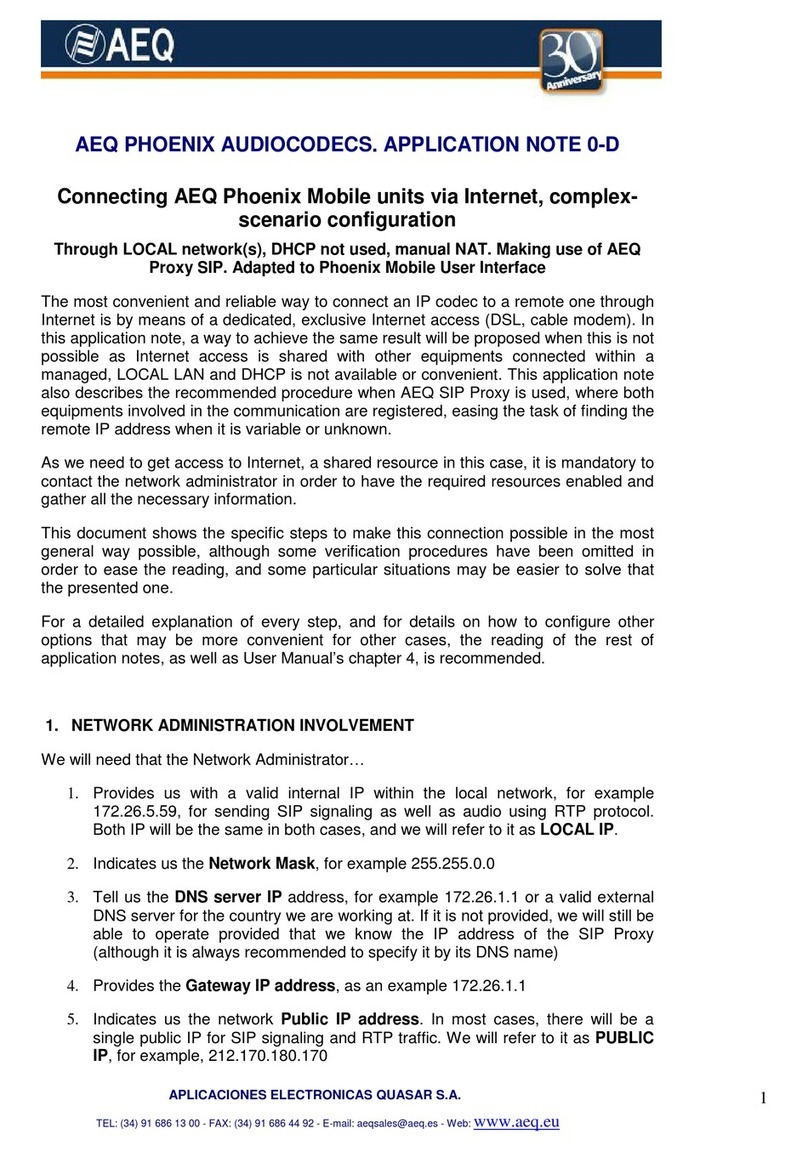
AEQ DIGITAL COMMENTARY UNIT Reference guide

A.E.Q., S.A. manufacturer of this equipment holds the AENOR ER-080/1/96
certificate according to UNE EN - ISO - 9001 Quality Standard
AEQ
DIGITAL COMMENTARY SYSTEM
CUSTOMER’S MANUAL
ED. 11/ 99
(VALID ONLY FOR EQUIPMENT WITH SOFTWARE VERSION CU V3.2 AND CM V3.4 Y3.5 OR HIGHER)

Digital Commentary System
-2-
AEQ DIGITAL COMMENTARY SYSTEM MANUAL INDEX
1.- Introduction to the Digital Commentary System
1.1.- General description
1.2.- Commentary unit (CU)
1.3.- Commentary Control Unit (CCU)
1.4.- Control software
2.- Commentary unit (CU)
2.1.- Features Description
2.2.- Functional diagram
2.3.- Installation & wiring
2.3.1.- Front panel description
2.3.1.1.- Micro headset connection
2.3.1.2.- Micro connection
2.3.1.3.- Tape connection
2.3.2.- Rear panel description
2.3.2.1.- Commentary Control Unit connection
2.3.2.2.- STAND ALONE connection
2.3.2.3.- Auxiliary line connection
2.3.2.4.- Control connection
2.3.2.5.- DIP switch configuration
2.3.2.6.- Power supply
2.3.3.- Lower panel description
2.3.3.1.- Input Sensibility adjust trimmers
2.4.- Description and operation
2.4.1.- Configuring the unit
2.4.2.- Working panel
2.4.2.1.- Commentator panel functions
2.4.2.2.- Mic/Tape functions
2.4.2.3.- Status functions
2.5.- Using the Commentary Unit (CU) with a Commentary Control Unit (CCU)
2.6.- STAND ALONE use
2.7.- Commentary unit specifications (functional and physical)
2.8.- Commentary unit specifications (electrical)

Digital Commentary System
-3-
3.- Commentary Control Unit (CCU)
3.1.- Features description
3.2.- Functional diagram
3.3.- Installation & wiring: rear panel description
3.3.1.- Monitor connections
3.3.2.- External specific connections
3.3.3.- Individual CU connection
3.3.4.- Mains switch, connector and fuses
3.4.- Description and operation : the working surface panel
3.4.1.- Introduction
3.4.2.- Control module (CM) functional description
3.4.2.1.- CM : Upper section
3.4.2.2.- CM : INTL SOUND section
3.4.2.3.- CM : Reference signals control section : GUIDE, AUX,
CUE
3.4.2.4.- CM : CU channels control section : COM1,2,3 and
MIC/LINE
3.4.2.5.- TAPE WITHOUT IS MIS
3.4.2.6.- CM : IDENTIFIER section (ID)
3.4.3.- Monitor module functional description
3.4.3.1.- MM : Upper section
3.4.3.2.- MM : Lower section
3.5.- Commentary Control Unit specifications (functional and physical).
3.6.- Commentary Control Unit specifications (electrical)
4.- Control software
4.1.- System overview
4.1.1.- System description
4.1.2.- System requirements
4.2.- Wiring the control network
4.2.1.- CCU wiring
4.2.2.- Control computer wiring
4.3.- Software installation
4.4.- Using the DCS Realtime Control software in a control network
4.4.1.- General overview
4.4.2.- Setting the network operational parameters
4.4.3.- Commentary System Network screen
4.4.4.- Commentary Control Unit monitor screen
4.4.5.- Commentary Control Module screen
4.4.6.- Commentary Unit screen
4.4.6.1.- The Commentary Unit screen
4.4.6.2.- Digital Level Processor (DLP)
4.4.6.2.1.- Independence of the DLP in a CU
4.4.6.2.2.- DLP Transfer Function
4.4.6.2.3.- Configuring the DLP
4.4.6.3.- HPF button
4.4.6.4.- Store audio parameters button

Digital Commentary System
-4-
4.4.6.5.- Retrieve audio parameters button
4.5.- Using the DCS Realtime Control software in a direct connection
4.5.1.- Controlling a single Commentary Unit
4.5.2.- Customizing the Commentary Unit audio parameters
4.5.3.- Remote control of the Commentary Unit using serial data
transmission
4.6.- Using the DCS Engineering Planning software
4.6.1.- Menu options
4.6.2.- Creating a new configuration file
4.6.3.- Opening an existing structure
4.6.4.- Adding and deleting elements in the network structure
4.6.5.- Assigning profiles to the elements
4.6.5.1.- Special Profiles : <NEW>
4.6.5.2.- Special Profiles : <NONE>
4.6.5.3.- Stored Profiles
APPENDIX 1: AEQ Warranty

Digital Commentary System
-5-
1.- INTRODUCTION TO THE DIGITAL COMMENTARY SYSTEM
The AEQ broadcaster digital commentary system was specially designed for
radio and television reporting. Its flexibility makes it versatile enough to be
used in most remote program situations.
The digital commentary system engineering and operational design meets
international broadcasters standards and requirements, making it very easy to
operate while preserving a high level of maintainability. Unit configuration and
functional changes are by software, and are centralized in the venue technical
control room and therefore can be accomplished in a very short time. It is also
possible to carry out these functions, via a modem, from the Program Control
Ccenter (PCC) or similar, located in the International Broadcasting Center
(IBC).
The controls of each Commentary Unit (CU) are easily accessible and their
number has been reduced to a minimum in order to simplify “on air” operation.
Controls are clearly identified by color and visual displays.
Normally at each venue the signal comes to each Commentary Unit (CU)
through a Commentary Control Unit console (CCU) consisting of ten
commentary modules and one associated monitor unit. Both units are
interconnected by digital cable.
A Commentary Control Unit (CCU) is not used at smaller events, the
commentary unit operates as a STAND ALONE, sending and receiving signals
through the analog inputs and outputs, while keeping remote control
capabilities through the built-in serial port.
Both, the CU and the CCU, accepts in-system programming, which insures an
easy and inexpensive way of system upgrading up to the latest available
version.

Digital Commentary System
-6-
1.1.- General description
Each Commentary System consists of ten commentator units (CU) connected
to a commentator console (CCU) through 4 pair data transmission STP or FTP
shielded cables used in data transmission.
The signals carried are as follows:
•Audio and control signals. There are two pairs for carrying digital data
related to audio feeds from commentators to the different output circuits, as
well as input signals to be monitored at the commentator’s side. Also
included are remote control signals, call signaling etc. The system includes
remote on field programming of the CU´s operational parameters (filtering,
AGC, compression etc.) and CU permanent software upgrade capabilities.

Digital Commentary System
-7-
•Power supply. There is a dedicated pair for remote CU powering from the
CCU. CUs can also be powered locally, using a external DC power supply.
•Auxiliary line. The system offers one pair for direct auxiliary line connection,
thus avoiding supplementary wiring costs.
Each commentator position at the venues will be equipped with a commentator
unit that can be used by up to three commentators and a guest announcer
simultaneously. The position of the guest announcer can also be used to
playback a pre-recorded tape. The Commentator Units have been designed to
provide the commentators with their own commentary circuit and easy access
to all their coordination talkback circuits.
Through their microphone headset combination, commentators have access to
the following circuits:
Their own commentary output circuit (Program).
•A choice of incoming signals such as International sound TV from the venue,
International sound Radio from the venue, Public Address (P.A.) system,
cues from the venue mobile producer, a local cue, beeping signals and an
optional feed from another commentator or cue circuit.
•Two-way communications with the venue technician responsible for the
commentary system and with the IBC or their home studio.

Digital Commentary System
-8-
1.2.- Commentary unit (CU)
The main function of this unit is to provide access to a combined microphone
headset for the broadcast of commentary or communication with a studio at the
IBC or the home country. The unit provides several operational possibilities,
which will vary in relation to the technical and operating criteria forecast for
each event, and in general are:
•The use of a microphone for commentary broadcast.
•Talkback from the producer at the IBC, studio or country to the commentator
at the venue.
•Commentator communication to the IBC studio or country producer.
•A return feed of the studio program output to the commentator.
•A feed which gives the results from the venue P.A. system.
•A two - way communications circuit between the commentator and the
operator at the Commentary Control Room (C.C.R.).
•Cue and venue information from the mobile producer.
•Cue information from additional organizations.
•Beeping signals of T’Back circuit.
•The option of disposing to listen the IS signal (preselected as the television
one or the radio one). from the competition site while broadcasting.
•The option of selecting a signal from the commentator GUIDE and an
auxiliary input (AUX) as a listening reference for the commentator to obtain
a data source for his commentaries.
All these functions are remotely controllable according to the technician’s
choice.

Digital Commentary System
-9-
1.3.- Commentary Control Unit (CCU)
The Commentary Control Unit (CCU) is designed to control and monitor up to
ten commentator signals from the commentator units, as well as provide the
required remote powering.
Each of the ten modular control sections has:
•a level meter for the PRG output
•an output selector (oscillator, ID, program)
•a digital mixing section, where the selected IS can be added to the
commentary signals to get the PROG/IS feed. The IS signal can be
upgraded by the Digital Level Processor (DLP). Audio parameters
associated with the DLP are fully programmable under the control software.
•A section to enable the AUX and GUIDE signals to the commentator
•A section for the routing and aperture of CUE 1 and CUE 2 signals to the
commentator
•An individual remote control and configuration section for each of the four
CU channels (COM 1, COM 2, COM 3 and MIC/LINE)
•A section for switching and signaling talkback calls
•A line identification section (ID) for the program and coordination circuits.
The monitor unit provides the operator with access to all program and cue
circuits for listening via a built-in speaker or set of earphones. A precision dB
meter is provided to measure absolute levels on all circuits. The unit also has
intercommunication functionality with the program and coordination circuits.
The monitor allows access to the local talk back circuit or a connection to the
external 4 wire circuit.
The power supply section, located on the rear panel, consists of two
independent modules, giving the redundancy level required for these types of
events. Each one of the modules is thus able to fulfill the power requirements of
the CCU and the associated CUs. The power supply design includes advanced
techniques like power factor correction, input voltage autoranging, high
efficiency switching conversion, etc.

Digital Commentary System
-10-
1.4.- Control software
The control software is a native 32 bits application, designed to run under
Windows 95 or Windows NT operating systems. It performs the following tasks:
•Can work in direct connection to a single CU, through the serial port, for
upgrading, setting audio parameters and real time remote controlling of the
unit.
•Can be used in a network configuration, carrying the full control of a given
number of CCUs and their associated CUs. Up to 32 CCUs (320 CUs) can
be controlled in this way.
•Performs real time supervision of the Commentary Control Network, using a
standard RS 485 (2 wire) interface. The required hardware is included in the
CCU as a standard option.
•Enables the user to define off-line configurations of the venue commentary
system, including audio and operational pre-settings. These pre-settings can
be downloaded to the real venue Commentary System. The setup time and
presetting tasks are dramatically reduced.
*Microsoft Corporation registered trademark

Digital Commentary System
-11-
2.- COMMENTARY UNIT (CU)
2.1 Features description
The Commentary Unit (CU) is the commentator’s interface to the AEQ Digital
Commentary System. It represents the final result of a wide variety of quality
and field tests, in which different aspects related to ergonomics, function, user
environment and operational costs have been carefully taken into account.
As does the rest of the system, the CU uses the latest available digital audio
and communications technology. Real time digital signal processing and
automation concepts have been used in order to increase the capabilities of the
system, while keeping the easiest user’s interface and a very high level of
protection against operational errors.
The equipment offers some unique features like:
Three operation modes:
-STAND ALONE self controlled digital mixer, with analog inputs and outputs.
-STAND ALONE digital mixer, with remote control through the serial interface.
-Remotely controllable digital mixer, when connected to the Commentary
Control Unit (CCU) by means of an inexpensive 4-pair FTP or STP cable and
an RJ-45 standard connector. The CU includes all the required circuitry to
perform a 5.4 Mb/s high reliability digital link to the CCU.

Digital Commentary System
-12-
Switching between the three available modes is automatic, on detection
of the communication clock signal sent from the CCU or the control
signals coming from the serial port.
•Digital Level Processor module on each one of the four input
channels. Much more than a limiter, the DLP is a single band audio
processor with a sophisticated level control algorithm, working as an
expander, compressor, limiter or unity gain amplifier, depending on
the signal’s peak power mean value. This characteristic gives
optimum utilization of the audio channel without the need for
continuous supervision by the technician.
•All audio parameters, attack and release time, gain slopes and knee
points, can be defined and stored in the CU through the serial
communications port.
•Flash EEPROM upgradeable technology. The equipment stores all
program and configuration data on non volatile memory, which can be
updated, or changed to the requirements of specific users via the RS-
232 connector and the supplied Windows 95 program.
•Includes a testing procedure for unit diagnostics and trouble detection
by technical staff.
•There are 4 different configurations stored on the CU which can be
called-up on power - up:
- 2 user defined configurations
- One special mode (required by BBC) which configures the COM 3
channel to be used by a program producer: the studiotalkback push-
button is then changed to latching mode, instead of the normal push-
to-talk mode.
- One operation procedure (ISMIX) to enable or disable the mix of
International Sound (IS) with PRG on the CU in order to suspend the
mix of IS and PRG when the line signal is sent by the tape recorder
channel.
•High quality magnetically shielded input transformers on all analog
inputs, with a high degree of RF protection.
•Wide input range DC/DC switching power supply; from 12 to 48 VDC.
•Local or remote powering with auto-switch function.
•Custom designed LCD symbols, for clear signaling of the CU status.
•The analog input and outputs are externally adjustable by high
precision trimmers.

Digital Commentary System
-13-
2.2 Functional diagram
Figure 2.2. CU Functional Diagram
The diagram displays the CU functional layout.
The signal generated in each of the four channels proceeds (through a high
pass filter HPF and a dynamic processor DLP, activated and configured

Digital Commentary System
-14-
remotely from the CCU) to the PROGRAM, TECH and STUDIO mixer circuits,
which are sent multiplexed digitally to the CCU.
The listening circuits permit each commentator to select the P.A., Guide, Aux,
IS and Program signals for his right earphone (and the rightf’back local analog
signal, if present).
These can be mixed for listening if desired, and are accompanied by the
specific coordination sounds for each commentator (CC/FB TO COM), labeled
on the front panel as “Coord RX”.
The signals set LOCAL T’B (TECH)/CUE/RINGER can be addressed from the
CCU to any ear (right, left or both).
The studio feedback PGM FB is sent to the left earphone with the analog signal
left f’b if present.
When a commentator speaks to the local CCU technician, the signal remains
separated from the program. The same happens when a commentator speaks
to the studio. The push-buttons (PTT) intercom ‘Push to Talk’ send the
commentator’s voice to the corresponding circuits.
The “Channel On” switch allows the commentator’s signal to be sent to the
program circuit. This can be remotely activated.
The “STAND ALONE” switch allows to send the commentator signal to the
program circuit. This switch can be activated remotely.
In “STAND ALONE” mode the left earphone simply receives the signals at the
corresponding “analog feedback left” banana plugs, while right earphone
receives the mix of the signal at the “analog feedback right” banana plugs with
the local program mixed in the CU.
When the unit is in STAND ALONE mode the program sound is the mix of of
the CU channels without including the sound from other external sources.
When the CU works in STAND ALONE mode, there is neither CUE nor Local
Talkback and Ringer arrives to the left ear. The intercommunication with the
CCU (LOC T/B) and CUE or the studio feedback are sent to the left earphone.

Digital Commentary System
-15-
2.3 Installation & wiring
To be able to clarify the installation and wiring process, it is necessary to be
familiar with the connectors and configurable elements (front and rear). It
should be remembered that this equipment is capable of functioning in
conjunction with a CCU or as a “STAND ALONE” unit, the necessary wiring
being distinct in either case.
2.3.1 Front panel description
The front panel houses one XLR audio connector aligned to each channel.
The commentator channels are supplied with a female XLR 7 pin connector,
usually for the connection of a micro-headset.
The Micro-Tape (LINE) channel is supplied with a female XLR 3 pin connector,
normally for the connection of a microphone or a portable tape recorder (LINE).
2.3.1.1 Micro headset connection
The micro - headset is normally supplied with plugs suitable for direct
connection to the CU. The connector wiring is given below:
1: Ground
2: Right earphone V+
3: Right earphone V-
4: Left earphone V+
5: Left earphone V-
6: Microphone V-
7: Microphone V+

Digital Commentary System
-16-
2.3.1.2 Micro connection
The microphones are normally supplied with suitable plugs for direct
connection to the CU. The connector wiring for special uses is given below:
1: Ground
2: Signal V+
3: Signal V-
2.3.1.3 Tape connection (LINE)
The cable to the tape-recorder must be connected normally, with the terminal to
the CU fitted with a 3 pin male XLR connector. The connector wiring is given
below, for both balanced and unbalanced line outputs.
Balanced line outputs:
1: Ground
2: Signal V+
3: Signal V-
Unbalanced line outputs:
1: Ground and Signal V-
2: Signal V+
3: Ground and Signal V-

Digital Commentary System
-17-
2.3.2 Rear panel description
The following facilities are situated on the rear panel:
- Local analog feedback connectors for left and right earphones (LEFT
F’BACK, RIGTH F’BACK) and trimmers for input level adjust ( LEVEL TRIM )
- Local auxiliary program output connector (MIXED OUT) and trimmers for
output level adjust (LEVEL TRIM)
- CCU communication connector (FROM CONTROL UNIT)
- Auxiliary line connector (AUXILIARY LINE)
- Data connector (CONTROL DATA PORT)
- Auxiliary power supply connector. (EXTERNAL DC INPUT)
Micro switch bank for power-up configuration selection (STARTUP
CONFIGURATION)
The following sections describe the elements listed above and their use.

Digital Commentary System
-18-
2.3.2.1 Commentary Control Unit connection
When the CU is working with a CCU, in addition to the micro-headphones for
commentators 1, 2 and 3, and the guest commentator microphone or tape
input, the links with the CCU also have to be wired.
When it works in conjunction with the CCU, a single 4 pair cable fitted with RJ
45 connectors receives and sends all the digitally multiplexed CCU working
signals, including the power supply and the analog telephone line.
The cable used must be a AWG24, STP or FTP Category 5 type, with four
twisted pairs. The connection at both sides will include the ground connection.
The male connector used will be a RJ-45, shielded, AMP-5-569530-4 or similar.
If a female-female extension is used, the ground connection (shield) continuity
must be granted.
With the wire described above a distance of 300 m. can be covered. In 2.3.2.5.
section, the equalization switch is described which must be set depending on
the length of the cable to be greater or less than 150 m.
RJ45 MALE CONNECTOR
The connections between the CCU and each of the CUs
are made without crossing the wires, maintaining the
relative position of the conductor in the RJ 45 connector.
The connector wiring is given below, showing the signals
carried by each conductor.
FRONT VIEW

Digital Commentary System
-19-
Wire Number Pair Number/Colour CU Connection CCU Connection
11 Green White DC mains 48V +DC mains 48 V+
22 Orange White Auxiliar line wire1 Auxiliar line wire1
33 Blue White Tx V+ Rx V+
44 Brown White Rx V+ Tx V+
54 Brown Rx V- Tx V-
63 Blue Tx V- Rx V-
72 Orange Auxiliar line wire 2 Auxiliar line wire 2
81 Green DC mains 48 V- DC mains 48 V-

Digital Commentary System
-20-
2.3.2.2 STAND ALONE connection
When the console is working alone without a CCU, in addition to the micro-
headphones for commentators 1, 2 and 3, and the guest commentator
microphone or a tape-recorder line output, the following links also have to be
wired:
The left channel input which carries the signals for listening in the left
earphone.
The right channel input which carries the signals for listening in the right
earphone.
The program mixed output carrying the commentators’ voice mix.
The connectors for MIXED OUTPUT, INPUT LEFT and INPUT RIGHT are 4
mm banana type, the positive (V+) are connected to the red terminal and the
negative (V-) are connected to the black terminal.
The external power supply must also be connected(DC 12-48V; 1 A @ 12V).
Table of contents
Other AEQ Recording Equipment manuals

AEQ
AEQ FORUM User manual

AEQ
AEQ FORUM User manual

AEQ
AEQ PAW 120 User manual

AEQ
AEQ Phoenix Mobile Installation and operating instructions

AEQ
AEQ PHOENIX ALIO User manual

AEQ
AEQ BRAVO User manual

AEQ
AEQ NETBOX DSP User manual

AEQ
AEQ FORUM LITE User manual

AEQ
AEQ PAW 120 Installation instructions

AEQ
AEQ NETBOX 4 MH User manual