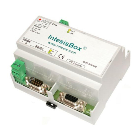
HMS Networks Intesis INMBSDAL0640000 User manual

Digitally Addressable Lighting Interface (DALI)
USER MANUAL
Issue date: 08/2019 r1.3 ENGLISH

IntesisTM Modbus Server –DALI User Manual r1.3 EN
© HMS Industrial Networks S.L.U - All rights reserved
This information is subject to change without notice
URL https://www.intesis.com
2 / 39
Important User Information
Disclaimer
The information in this document is for informational purposes only. Please inform HMS Industrial Networks of any
inaccuracies or omissions found in this document. HMS Industrial Networks disclaims any responsibility or liability for
any errors that may appear in this document.
HMS Industrial Networks reserves the right to modify its products in line with its policy of continuous product
development. The information in this document shall therefore not be construed as a commitment on the part of
HMS Industrial Networks and is subject to change without notice. HMS Industrial Networks makes no commitment to
update or keep current the information in this document.
The data, examples and illustrations found in this document are included for illustrative purposes and are only
intended to help improve understanding of the functionality and handling of the product. In view of the wide range of
possible applications of the product, and because of the many variables and requirements associated with any
particular implementation, HMS Industrial Networks cannot assume responsibility or liability for actual use based on
the data, examples or illustrations included in this document nor for any damages incurred during installation of the
product. Those responsible for the use of the product must acquire sufficient knowledge in order to ensure that the
product is used correctly in their specific application and that the application meets all performance and safety
requirements including any applicable laws, regulations, codes and standards. Further, HMS Industrial Networks will
under no circumstances assume liability or responsibility for any problems that may arise as a result from the use of
undocumented features or functional side effects found outside the documented scope of the product. The effects
caused by any direct or indirect use of such aspects of the product are undefined and may include e.g. compatibility
issues and stability issues.

IntesisTM Modbus Server –DALI User Manual r1.3 EN
© HMS Industrial Networks S.L.U - All rights reserved
This information is subject to change without notice
URL https://www.intesis.com
3 / 39
Gateway for integration of DALI devices into Modbus (RTU and
TCP) systems.
ORDER CODE
LEGACY ORDER CODE
INMBSDAL0640000
IBMBSDAL0640000
INMBSDAL1280000
IBMBSDAL1280000

IntesisTM Modbus Server –DALI User Manual r1.3 EN
© HMS Industrial Networks S.L.U - All rights reserved
This information is subject to change without notice
URL https://www.intesis.com
4 / 39
INDEX
1Description ............................................................................................................................................................5
Introduction....................................................................................................................................................5
Functionality ..................................................................................................................................................6
Gateway’s capacity .......................................................................................................................................6
2Modbus interface...................................................................................................................................................8
Functions supported......................................................................................................................................8
Modbus RTU .................................................................................................................................................8
Modbus TCP..................................................................................................................................................8
Modbus Address Map ...................................................................................................................................9
2.4.1 Single DALI device signals....................................................................................................................9
2.4.2 DALI groups’ signals............................................................................................................................17
2.4.3 Broadcast signals ................................................................................................................................19
3Connections ........................................................................................................................................................22
Powering the device....................................................................................................................................24
Connection to DALI channel........................................................................................................................24
Connection to Modbus ................................................................................................................................24
3.3.1 Modbus TCP........................................................................................................................................24
3.3.2 Modbus RTU........................................................................................................................................24
Connection to PC (Configuration tool) ........................................................................................................24
4Set-up process and troubleshooting ...................................................................................................................25
Pre-requisites ..............................................................................................................................................25
Intesis MAPS. Configuration & monitoring tool for Intesis ..........................................................................25
4.2.1 Introduction..........................................................................................................................................25
4.2.2 Connection...........................................................................................................................................25
4.2.3 Configuration tab .................................................................................................................................26
4.2.4 Signals.................................................................................................................................................27
4.2.5 Sending the configuration to Intesis ....................................................................................................28
4.2.6 Diagnostic............................................................................................................................................29
Set-up procedure.........................................................................................................................................30
5Electrical & Mechanical Features........................................................................................................................31
6Dimensions .........................................................................................................................................................32
Annex A –Quick setup and commissioning of a DALI network...............................................................................33
Create project..............................................................................................................................................33
ECG declaration in project ..........................................................................................................................34
Scan and commissioning of ECGs..............................................................................................................35

IntesisTM Modbus Server –DALI User Manual r1.3 EN
© HMS Industrial Networks S.L.U - All rights reserved
This information is subject to change without notice
URL https://www.intesis.com
5 / 39
1 Description
Introduction
This document describes the integration of DALI lighting ballasts into Modbus compatible devices and systems using
the Intesis Modbus Server to DALI communication gateway.
The aim of this integration is to monitor and control DALI lighting ballasts, remotely, from your Control Center using
any commercial SCADA or monitoring software that includes a Modbus Master driver (RTU and/or TCP). To do it so,
Intesis performs as a Modbus Server, allowing poll and write requests from any Modbus master device.
In current version of the device, following DALI device types are supported:
•DALI Fluorescent lights (DALI type 0)
•Emergency lights (DALI type 1)
•LED modules (DALI type 6)
All of them, regardless of its type, will be referred as ‘ballasts’, ‘DALI devices’ and ‘ECGs’ (Electronic Control Gears)
indistinctively throughout the document.
Up to 64 DALI lighting devices can be fitted in a single DALI channel, and therefore controlled and monitored from
Intesis. Depending on the version of the gateway, 1 line (64 lighting devices) or 2 lines (128 lighting devices) are
supported.
Version supporting 2 DALI channels does not have support for Modbus RTU –it’s a Modbus TCP-only device.
Intesis needs to be configured using Intesis MAPS software configuration tool. In the software, Modbus and DALI
lighting ballast parameters must be configured and downloaded to the Intesis.
This document assumes the user is familiar with Modbus and DALI technologies and technical terms.
Integration of DALI into
Modbus TCP / Modbus RTU control systems (product version supporting 1 DALI channel)
Modbus TCP
Modbus RTU
USB
configuration
Ethernet TCP
Ethernet
configuration
DALI (up to 64 ballasts in a line)
NOTE: There may be differences in the implementation of DALI among different
ballasts and manufacturers. Intesis is compatible with Ballasts implementing the DALI
standard and certified under the DiiA guidelines for testing and certification. Use only
DALI devices having the DALI logo with Intesis.
!

IntesisTM Modbus Server –DALI User Manual r1.3 EN
© HMS Industrial Networks S.L.U - All rights reserved
This information is subject to change without notice
URL https://www.intesis.com
6 / 39
Integration of DALI into
Modbus TCP / Modbus RTU control systems (product version supporting 2 DALI channels)
Functionality
IntesisTM continuously polls (reads) all the signals of the DALI lighting ballasts in each line and maintains the updated
values to be served in Modbus.
When a write is done from Modbus in a gateway's Modbus writeable address, the corresponding command is sent to
the corresponding DALI lighting ballast.
In the continuous polling process of the DALI channel, if there is no answer, it is indicated with a virtual signal of
communication error for this ballast in its line.
The IP address and communication parameters for Modbus side of the gateway (TCP or RTU) must be set in the
MAPS configuration tool.
From the configuration tool, it is also possible to scan each DALI channel for available ballasts, add them in
configuration, and configure its individual parameters (short address, preset levels, scenes, etc), according to their
device type (fluorescent light, emergency light, LED module).
Gateway’s capacity
Intesis capacity is listed below:
Element
Max.
Notes
Number of DALI channels
2
Number of independent DALI channels
Number DALI lighting devices
per line
64
64 DALI lighting devices are supported per line
Max number of Modbus
variables per DALI device
61
Number of available signals will vary according to device
type
Max number of Modbus
variables per DALI group
16
Number of available signals will vary according to device
type
Max number of variables per
LINE
4176
16 broadcast signals + 16 signals/DALI group + 61
signals/DALI device
Modbus TCP
USB
configuration
Ethernet TCP
Ethernet
configuration
DALI (up to 64 ballasts in a line)
DALI (up to 64 ballasts in a line)

IntesisTM Modbus Server –DALI User Manual r1.3 EN
© HMS Industrial Networks S.L.U - All rights reserved
This information is subject to change without notice
URL https://www.intesis.com
7 / 39
There are 2 different models of IntesisTM Modbus Server –DALI with different capacity. The table above shows the
capacity for the top model (with maximum capacity).
The 2 different models allow integrating respectively: 1 or 2 DALI channels.
Their order codes are:
•INMBSDAL0640000. Model supporting 1 DALI channel (up to 64 DALI devices)
•INMBSDAL1280000. Model supporting 2 DALI channels (up to 64 DALI devices per channel, 128 in total)

IntesisTM Modbus Server –DALI User Manual r1.3 EN
© HMS Industrial Networks S.L.U - All rights reserved
This information is subject to change without notice
URL https://www.intesis.com
8 / 39
2 Modbus interface
Functions supported
This part is common for Modbus RTU and TCP.
Modbus functions 03 and 04 (Read Holding Registers and Read Input Registers) can be used to read Modbus
registers.
Modbus functions 06 and 16 (Single Multiple Holding Registers and Write Multiple Holding Registers) can be used to
write Modbus registers.
Configuration of poll records is possible between Modbus addresses 0 and 20000. Addresses that are not defined in
section 2.4 (Modbus map of the device) are read-only and will always report 0.
Modbus error codes are supported, they will be sent whenever a non-valid Modbus address is queried.
All registers are 16-bit signed integer, in standard Modbus Big Endian (MSB/LSB) format.
Intesis supports Modbus RTU and Modbus TCP and both interfaces can be used simultaneously.
Modbus RTU
Modbus RTU is only available in version of the product supporting 1 DALI channel. Product version supporting 2 DALI
channels provides support for Modbus TCP only.
Whenpresent, both EIA485 and EIA232 physical layers are supported. Only the lines RX, TX and GND of the EIA232
connector are used (TX and RX for EIA485).
Baud rate can be selected between 1200, 2400, 4800, 9600, 19200, 38400, 56700 and 115200. Parity (none, even
or odd) and stop bits (1 or 2) can be selected as well.
Modbus slave number must be configured and the physical connection (RS232 or RS485) can also be selected.
Modbus TCP
TCP port to use (default is 502) and keep alive period must be configured.
IP settings of Intesis (DHCP status, own IP, net mask and default gateway) must be configured as well.

IntesisTM Modbus Server –DALI User Manual r1.3 EN
© HMS Industrial Networks S.L.U - All rights reserved
This information is subject to change without notice
URL https://www.intesis.com
9 / 39
Modbus Address Map
Note that this map only applies when Modbus Addresses parameter is set to Fixed. For more information about configuration of Modbus Addresses parameter see
Intesis MAPS Modbus Server User Manual.
2.4.1 Single DALI device signals
There are up to 94 signals for each DALI device or ballast. Their Modbus addresses can be obtained applying the following formula:
Modbus Address = 7000 x CHANNEL + (100 x BALLAST) + SIGNAL NUMBER
Where:
CHANNEL NUMBER; 0..1 (always 0 if using version with support for 1 DALI channel)
BALLAST NUMBER: 0..63 (ballast short address)
SIGNAL NUMBER: 0..93, see following table
Modbus address from the formula is expressed in link layer format. This is, first register address is 0.
Supported signals vary according to device type. Following abbreviations are done in the table:
•FL: Fluorescent light (device type 0)
•EML: Emergency light (device type 1)
•LED: LED module (device type 6)
Modbus Address
First Address is 0
Ballast /
Device type
Read/
Write
Register/signal name
Possible values
FL
EML
LED
7000 x channel + (100 x sa)
+ 0
channel stands for DALI channel and is 0 or 1
sa stands for short address and is 0 to 63
x
x
x
R
Ballast / Lamp Failure bit fields
(ECG15-ECG0)
0-OK, 1-Ballast / Lamp Failure bi[i= sa - (16 * (line-1))]
7000 x channel + (100 x sa)
+ 1
x
x
x
R
Ballast / Lamp Failure bit fields
(ECG31-ECG16)
0-OK, 1-Ballast / Lamp Failure bi[i= sa - (16 * (line-1))]
7000 x channel + (100 x sa)
+ 2
x
x
x
R
Ballast / Lamp Failure bit fields
(ECG47-ECG32)
0-OK, 1-Ballast / Lamp Failure bi[i= sa - (16 * (line-1))]

IntesisTM Modbus Server –DALI User Manual r1.3 EN
© HMS Industrial Networks S.L.U - All rights reserved
This information is subject to change without notice
URL https://www.intesis.com
10 / 39
Modbus Address
First Address is 0
Ballast /
Device type
Read/
Write
Register/signal name
Possible values
FL
EML
LED
7000 x channel + (100 x sa)
+ 3
x
x
x
R
Ballast / Lamp Failure bit fields
(ECG63-ECG48)
0-OK, 1-Ballast / Lamp Failure bi[i= sa - (16 * (line-1))]
7000 x channel + (100 x sa)
+ 4
x
x
x
R/W
Update All ECG Status
0-Update Finished, 1-Trigger Update
7000 x channel + (100 x sa)
+ 5
x
x
x
R
Ballast Status
b7-PwrCycle, b6-MissShAdd, b5-ResetSt, b4-FadeRun,
b3-BallLimErr, b2-LampPwrOn, b1-LampFail, b0-BallFail
7000 x channel + (100 x sa)
+ 6
x
x
x
R
Actual Level
0 to 100 %
7000 x channel + (100 x sa)
+ 7
x
x
x
R
Device Type
0-Fluorescent, 1-Emergency, 2 Discharge, 3-Halogen, 4-
Incandescent, 5-Digital signal, 6-LED, 7-Switching, 8-
Colour Control
7000 x channel + (100 x sa)
+ 8
x
x
x
R
Physical Minimum Level
0 to 100 %
7000 x channel + (100 x sa)
+ 9
x
x
x
R
Min Level
0 to 100 %
7000 x channel + (100 x sa)
+ 10
x
x
x
R
Max Level
0 to 100 %
7000 x channel + (100 x sa)
+ 11
x
x
x
R
Power On Level
0 to 100 %
7000 x channel + (100 x sa)
+ 12
x
x
x
R
System Failure Level
0 to 100 %
7000 x channel + (100 x sa)
+ 13
x
x
x
R
Fade Time
0 to 15
7000 x channel + (100 x sa)
+ 14
x
x
x
R
Fade Rate
1 to 15
7000 x channel + (100 x sa)
+ 15
x
x
x
R/W
Arc Power Level
0 to 100 %

IntesisTM Modbus Server –DALI User Manual r1.3 EN
© HMS Industrial Networks S.L.U - All rights reserved
This information is subject to change without notice
URL https://www.intesis.com
11 / 39
Modbus Address
First Address is 0
Ballast /
Device type
Read/
Write
Register/signal name
Possible values
FL
EML
LED
7000 x channel + (100 x sa)
+ 16
x
x
x
R/W
Arc Power Off / On
0-Off; 1-100 %
7000 x channel + (100 x sa)
+ 17
x
x
x
R/W
Step Down / Up
0-Step Down, 1-Step Up
7000 x channel + (100 x sa)
+ 18
x
x
x
W
(trigge
r)
Recall Min Level
1-Recall Min Level
7000 x channel + (100 x sa)
+ 19
x
x
x
W
(trigge
r)
Recall Max Level
1-Recall Max Level
7000 x channel + (100 x sa)
+ 20
x
x
x
R/W
Go to Scene
0 to 15
7000 x channel + (100 x sa)
+ 21
x
x
x
R/W
Store Current Level as Scene
0 to 15
7000 x channel + (100 x sa)
+ 22
x
x
x
R/W
Clear/Remove Scene
0 to 15
7000 x channel + (100 x sa)
+ 23
x
x
x
R/W
Set Fade Time
0 to 15
7000 x channel + (100 x sa)
+ 24
x
x
x
R/W
Set Fade Rate
1 to 15
7000 x channel + (100 x sa)
+ 25
x
x
x
R/W
Set Min Level
0 to 100 %
7000 x channel + (100 x sa)
+ 26
x
x
x
R/W
Set Max Level
0 to 100 %
7000 x channel + (100 x sa)
+ 27
x
x
x
R/W
Set Power-on Level
0 to 100 %
7000 x channel + (100 x sa)
+ 28
x
x
x
R/W
Set System-failure Level
0 to 100 %

IntesisTM Modbus Server –DALI User Manual r1.3 EN
© HMS Industrial Networks S.L.U - All rights reserved
This information is subject to change without notice
URL https://www.intesis.com
12 / 39
Modbus Address
First Address is 0
Ballast /
Device type
Read/
Write
Register/signal name
Possible values
FL
EML
LED
7000 x channel + (100 x sa)
+ 29
R
Not used
Default to 0
7000 x channel + (100 x sa)
+ 30
R
Not used
Default to 0
7000 x channel + (100 x sa)
+ 31
R
Not used
Default to 0
7000 x channel + (100 x sa)
+ 32
R
Not used
Default to 0
7000 x channel + (100 x sa)
+ 33
R
Not used
Default to 0
7000 x channel + (100 x sa)
+ 34
R
Not used
Default to 0
7000 x channel + (100 x sa)
+ 35
x
R/W
Set System-failure Level
0 to 100 %
7000 x channel + (100 x sa)
+ 36
R
Not used
Default to 0
7000 x channel + (100 x sa)
+ 37
R
Not used
Default to 0
7000 x channel + (100 x sa)
+ 38
R
Not used
Default to 0
7000 x channel + (100 x sa)
+ 39
R
Not used
Default to 0
7000 x channel + (100 x sa)
+ 40
R
Not used
Default to 0
7000 x channel + (100 x sa)
+ 41
R
Not used
Default to 0

IntesisTM Modbus Server –DALI User Manual r1.3 EN
© HMS Industrial Networks S.L.U - All rights reserved
This information is subject to change without notice
URL https://www.intesis.com
13 / 39
Modbus Address
First Address is 0
Ballast /
Device type
Read/
Write
Register/signal name
Possible values
FL
EML
LED
7000 x channel + (100 x sa)
+ 42
x
R
Failure Status
b7-FunctFail, b6-DurFail, b5-DurTestDelay, b4-
FunctTestDelay, b3-EmLampFail, b2-BattFail, b1-
BattDurFail, b0-CircFail
7000 x channel + (100 x sa)
+ 43
x
R
Emergency Mode
b7-HardSwOn, b6-HardInhibit, b5-DurTestProg, b4-
FunctTestProg, b3-ExtdEmMode, b2-EmMode, b1-
NormMode, b0-RestMode
7000 x channel + (100 x sa)
+ 44
x
R
Emergency Status
b7-PhysicSel, b6-Ident, b5-DurTestPend, b4-
FunctTestPend, b3-BattFull, b2-DurTestDone, b1-
FunctTestDone, b0-InhibitMode
7000 x channel + (100 x sa)
+ 45
x
R
Emergency Battery Charge
0 to 100 %
7000 x channel + (100 x sa)
+ 46
x
R
Next Function Test
0 to 16384 hours
7000 x channel + (100 x sa)
+ 47
x
R
Next Duration Test
0 to 16384 hours
7000 x channel + (100 x sa)
+ 48
x
R
Function Test Interval
0-Disabled, 1 to 255 days
7000 x channel + (100 x sa)
+ 49
x
R
Duration Test Interval
0-Disabled, 1 to 97 weeks
7000 x channel + (100 x sa)
+ 50
x
R
Test Execution Timeout
0 to 255 days
7000 x channel + (100 x sa)
+ 51
x
R
Prolong Time
0 to 127,5 minutes
7000 x channel + (100 x sa)
+ 52
x
R
Duration Test Result
0 to 510 minutes
7000 x channel + (100 x sa)
+ 53
x
R
Lamp Total Operation Time
0 to 1016 hours

IntesisTM Modbus Server –DALI User Manual r1.3 EN
© HMS Industrial Networks S.L.U - All rights reserved
This information is subject to change without notice
URL https://www.intesis.com
14 / 39
Modbus Address
First Address is 0
Ballast /
Device type
Read/
Write
Register/signal name
Possible values
FL
EML
LED
7000 x channel + (100 x sa)
+ 54
x
R
Emergency Level
0 to 100 %
7000 x channel + (100 x sa)
+ 55
x
R
Emergency Min Level
0 to 100 %
7000 x channel + (100 x sa)
+ 56
x
R
Emergency Max Level
0 to 100 %
7000 x channel + (100 x sa)
+ 57
x
R
Rated Duration
0 to 510 minutes
7000 x channel + (100 x sa)
+ 58
x
R
Features
b7-RelightRestSup, b6-PhysicSelSup, b5-HardInSup, b4-
AdjsEmLvl, b3-AutoTestCap, b2-SwitchMainCG, b1-
MainCG, b0-IntegralEmCG
7000 x channel + (100 x sa)
+ 59
x
R
Lamp Emergency Time
0 to 254 hours
7000 x channel + (100 x sa)
+ 60
x
W
Rest
1-Extinguish Lamp
7000 x channel + (100 x sa)
+ 61
x
W
Inhibit
1-Start Inhibit mode
7000 x channel + (100 x sa)
+ 62
x
W
Re-Light/Reset Inhibit
1-Cancel Inhibit Mode
7000 x channel + (100 x sa)
+ 63
x
W
Start Function Test
1-Start Function Test
7000 x channel + (100 x sa)
+ 64
x
W
Start Duration Test
1-Start Duration Test
7000 x channel + (100 x sa)
+ 65
x
W
Stop Test
1-Stop Function/Duration Test
7000 x channel + (100 x sa)
+ 66
x
W
Reset Function Test Done Flag
1-Reset Function Flag

IntesisTM Modbus Server –DALI User Manual r1.3 EN
© HMS Industrial Networks S.L.U - All rights reserved
This information is subject to change without notice
URL https://www.intesis.com
15 / 39
Modbus Address
First Address is 0
Ballast /
Device type
Read/
Write
Register/signal name
Possible values
FL
EML
LED
7000 x channel + (100 x sa)
+ 67
x
W
Reset Duration Test Done Flag
1-Reset Duration Flag
7000 x channel + (100 x sa)
+ 68
x
W
Reset Lamp Time
1-Lamp Emergency Time Reset
7000 x channel + (100 x sa)
+ 69
x
R/W
Store Test Execution Timeout
0 to 255 days
7000 x channel + (100 x sa)
+ 70
x
R/W
Store Prolong Time
0 to 127,5 minutes
7000 x channel + (100 x sa)
+ 71
x
R/W
Store Function Test Interval
0-Disabled, 1 to 255 days
7000 x channel + (100 x sa)
+ 72
x
R/W
Store Duration Test Interval
0-Disabled, 1 to 97 weeks
7000 x channel + (100 x sa)
+ 73
x
R/W
Store Emergency Level
0 to 100 %
7000 x channel + (100 x sa)
+ 74
R
Not used
Default to 0
7000 x channel + (100 x sa)
+ 75
R
Not used
Default to 0
7000 x channel + (100 x sa)
+ 76
R
Not used
Default to 0
7000 x channel + (100 x sa)
+ 77
R
Not used
Default to 0
7000 x channel + (100 x sa)
+ 78
R
Not used
Default to 0
7000 x channel + (100 x sa)
+ 79
R
Not used
Default to 0

IntesisTM Modbus Server –DALI User Manual r1.3 EN
© HMS Industrial Networks S.L.U - All rights reserved
This information is subject to change without notice
URL https://www.intesis.com
16 / 39
Modbus Address
First Address is 0
Ballast /
Device type
Read/
Write
Register/signal name
Possible values
FL
EML
LED
7000 x channel + (100 x sa)
+ 80
x
R
Failure Status
b7-RefMeasurFail, b6-ThermLightLvl, b5-ThermShut, b4-
CurrProtAct, b3-LoadInc, b2-LoadDec, b1-OpenC, b0-
ShortC
7000 x channel + (100 x sa)
+ 81
x
R
Gear Type
b3-dcSuppPoss, b2-acSuppPoss, b1-LEDModInt, b0-
LEDPowerSInt
7000 x channel + (100 x sa)
+ 82
x
R
Dimming Curve
0-Standard Logarithmic Dim Curve, 1-Linear Dim Curve
7000 x channel + (100 x sa)
+ 83
x
R
Possible Operating Modes
b3-HighCurrPulMod, b2-OutCurrContr, b1-AMModePoss,
b0-PWMModePoss
7000 x channel + (100 x sa)
+ 84
x
R
Features
b7-PhysicSelSupp, b6-LightLvlRedReq, b5-
ThermShutReq, b4-CurrProtActReq, b3-LoadIncReq, b2-
LoadDecReq, b1-OpenCQ, b0-ShortCQ
7000 x channel + (100 x sa)
+ 85
x
R
Reference Running
0-No, 1-Yes
7000 x channel + (100 x sa)
+ 86
x
R
Current Protector
0-Disabled, 1-Enabled
7000 x channel + (100 x sa)
+ 87
x
R
Operating Mode
b4-NonLogDimCurveAct, b3-HighCurrPulModeAct, b2-
OutCurrContr, b1-AMModeAct, b0-PWMModeAct
7000 x channel + (100 x sa)
+ 88
x
R
Fast Fade Time
0 to 27
7000 x channel + (100 x sa)
+ 89
x
R
Min Fast Fade Time
0 to 27
7000 x channel + (100 x sa)
+ 90
x
W
Reference System Power
1-Trigger DALI Power Referencing
7000 x channel + (100 x sa)
+ 91
x
R/W
Enable/Disable Current Protector
0-Disable, 1-Enable
7000 x channel + (100 x sa)
+ 92
x
R/W
Select Dimming Curve
0-Standard Logarithmic Dim Curve, 1-Linear Dim Curve

IntesisTM Modbus Server –DALI User Manual r1.3 EN
© HMS Industrial Networks S.L.U - All rights reserved
This information is subject to change without notice
URL https://www.intesis.com
17 / 39
Modbus Address
First Address is 0
Ballast /
Device type
Read/
Write
Register/signal name
Possible values
FL
EML
LED
7000 x channel + (100 x sa)
+ 93
x
R/W
Store Fast Fade Time
0 to 27
2.4.2 DALI groups’ signals
DALI supports group addressing of ballasts. Up to 16 groups can be defined in a DALI channel. In Intesis, there are up to 16 signals for each DALI group. Their Modbus
addresses can be obtained applying the following formula:
Modbus Address = 7000 x channel + (20 x GROUP) + SIGNAL NUMBER
Where:
LINE NUMBER; 0..1 (always 0 if using version with support for 1 DALI channel)
GROUP NUMBER: 0..15 (ballast group)
SIGNAL NUMBER: 6400..6415, see following table
Modbus address from the formula is expressed in link layer format. This is, first register address is 0.
Supported signals vary according to device type. Following abbreviations are done in the table:
•FL: Fluorescent light (device type 0)
•EML: Emergency light (device type 1)
•LED: LED module (device type 6)
Modbus Address
First Address is 0
Ballast /
Device type
Read/
Write
Register/signal name
Possible values
FL
EML
LED
7000 * line + (20 * gr) + 6400
line stands for DALI channel and is 0 or 1
gr stands for DALI group and is 0 to 15
x
x
x
R/W
Arc Power Level
0 to 100 %

IntesisTM Modbus Server –DALI User Manual r1.3 EN
© HMS Industrial Networks S.L.U - All rights reserved
This information is subject to change without notice
URL https://www.intesis.com
18 / 39
Modbus Address
First Address is 0
Ballast /
Device type
Read/
Write
Register/signal name
Possible values
FL
EML
LED
7000 * line + (20 * gr) + 6401
x
x
x
R/W
Arc Power Off / On
0-Off; 1-100 %
7000 * line + (20 * gr) + 6402
x
x
x
R/W
Step Down / Up
0-Step Down, 1-Step Up
7000 * line + (20 * gr) + 6403
x
x
x
W
Recall Min Level
1-Recall Min Level
7000 * line + (20 * gr) + 6404
x
x
x
W
Recall Max Level
1-Recall Max Level
7000 * line + (20 * gr) + 6405
x
x
x
R/W
Go to Scene
0 to 15
7000 * line + (20 * gr) + 6406
x
x
x
R/W
Store Current Level as Scene
0 to 15
7000 * line + (20 * gr) + 6407
x
x
x
R/W
Clear/Remove Scene
0 to 15
7000 * line + (20 * gr) + 6408
x
x
x
R/W
Set Fade Time
0 to 15
7000 * line + (20 * gr) + 6409
x
x
x
R/W
Set Fade Rate
1 to 15
7000 * line + (20 * gr) + 6410
x
x
x
R/W
Set Min Level
0 to 100 %
7000 * line + (20 * gr) + 6411
x
x
x
R/W
Set Max Level
0 to 100 %
7000 * line + (20 * gr) + 6412
x
x
x
R/W
Set Power-on Level
0 to 100 %
7000 * line + (20 * gr) + 6413
x
x
x
R/W
Set System-failure Level
0 to 100 %

IntesisTM Modbus Server –DALI User Manual r1.3 EN
© HMS Industrial Networks S.L.U - All rights reserved
This information is subject to change without notice
URL https://www.intesis.com
19 / 39
Modbus Address
First Address is 0
Ballast /
Device type
Read/
Write
Register/signal name
Possible values
FL
EML
LED
7000 * line + (20 * gr) + 6414
x
R/W
Burn-in time Status
0-Stopped, 1-Running
7000 * line + (20 * gr) + 6415
x
R/W
Burn-in time
0-Stop, 1-Start
2.4.3 Broadcast signals
Broadcast signals allow to control all ballasts in the same line from an individual signal. Their Modbus addresses can be obtained applying the following formula:
Modbus Address = 7000 x channel + SIGNAL NUMBER
Where:
LINE NUMBER; 0..1 (always 0 if using version with support for 1 DALI channel)
SIGNAL NUMBER: 6800..6815, see following table
Modbus address from the formula is expressed in link layer format. This is, first register address is 0.
Supported signals vary according to device type. Following abbreviations are done in the table:
•FL: Fluorescent light (device type 0)
•EML: Emergency light (device type 1)
•LED: LED module (device type 6)

IntesisTM Modbus Server –DALI User Manual r1.3 EN
© HMS Industrial Networks S.L.U - All rights reserved
This information is subject to change without notice
URL https://www.intesis.com
20 / 39
Modbus Address
First Address is 0
Ballast /
Device type
Read/
Write
Register/signal name
Possible values
FL
EML
LED
7000 * line + 6800
line stands for DALI channel and is 0 or 1
x
x
x
R/W
Arc Power Level
0 to 100 %
7000 * line + 6801
x
x
x
R/W
Arc Power Off / On
0-Off; 1-100 %
7000 * line + 6802
x
x
x
R/W
Step Down / Up
0-Step Down, 1-Step Up
7000 * line + 6803
x
x
x
W
Recall Min Level
1-Recall Min Level
7000 * line + 6804
x
x
x
W
Recall Max Level
1-Recall Max Level
7000 * line + 6805
x
x
x
R/W
Go to Scene
0 to 15
7000 * line + 6806
x
x
x
R/W
Store Current Level as Scene
0 to 15
7000 * line + 6807
x
x
x
R/W
Clear/Remove Scene
0 to 15
7000 * line + 6808
x
x
x
R/W
Set Fade Time
0 to 15
7000 * line + 6809
x
x
x
R/W
Set Fade Rate
1 to 15
7000 * line + 6810
x
x
x
R/W
Set Min Level
0 to 100 %
7000 * line + 6811
x
x
x
R/W
Set Max Level
0 to 100 %
7000 * line + 6812
x
x
x
R/W
Set Power-on Level
0 to 100 %
This manual suits for next models
3
Table of contents
Other HMS Networks Server manuals
Popular Server manuals by other brands
LOXONE
LOXONE 200120 quick start guide
IBM
IBM 86655RY - Netfinity 7600 - 8665 Hardware Maintenance Manual
Advantech
Advantech EKI-1351 user manual
Fujitsu
Fujitsu SPARC Enterprise M4000 Overview guide
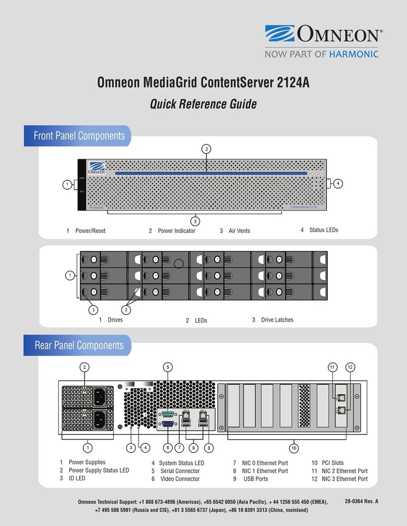
Omneon
Omneon MediaGrid ContentServer 2124A Quick reference guide

Lenovo
Lenovo ThinkServer TD100 Guide d'utilisation
IBM
IBM x3100 user guide
Paxton10
Paxton10 INS-01001 user manual
B&B Electronics
B&B Electronics Serial Servers Vlinx VESR9xx instruction manual
Lightwave Communications
Lightwave Communications SCS3230 System administrator guide
Fujitsu
Fujitsu PRIMERGY RX4770 M4 operating manual

Gooxi
Gooxi Purley Platform 1U product manual
