HMS Anybus ABC4011 User manual

Anybus®Communicator™- EtherNet/IP™Adapter to Modbus TCP Server
USER MANUAL
SCM-1202-196
Version 1.0
Publicaon date 2022-08-31
ENGLISH

Important User Informaon
Disclaimer
The informaon in this document is for informaonal purposes only. Please inform HMS Networks of any
inaccuracies or omissions found in this document. HMS Networks disclaims any responsibility or liability for any
errors that may appear in this document.
HMS Networks reserves the right to modify its products in line with its policy of connuous product
development. The informaon in this document shall therefore not be construed as a commitment on the
part of HMS Networks and is subject to change without noce. HMS Networks makes no commitment to update
or keep current the informaon in this document.
The data, examples and illustraons found in this document are included for illustrave purposes and are only
intended to help improve understanding of the funconality and handling of the product. In view of the wide
range of possible applicaons of the product, and because of the many variables and requirements associated
with any parcular implementaon, HMS Networks cannot assume responsibility or liability for actual use
based on the data, examples or illustraons included in this document nor for any damages incurred during
installaon of the product. Those responsible for the use of the product must acquire sucient knowledge in
order to ensure that the product is used correctly in their specic applicaon and that the applicaon meets all
performance and safety requirements including any applicable laws, regulaons, codes and standards. Further,
HMS Networks will under no circumstances assume liability or responsibility for any problems that may arise as
a result from the use of undocumented features or funconal side eects found outside the documented scope
of the product. The eects caused by any direct or indirect use of such aspects of the product are undened and
may include e.g. compability issues and stability issues.
Copyright © 2022 HMS Networks
Contact Informaon
Postal address:
Box 4126
300 04 Halmstad, Sweden
E-Mail: inf[email protected]

Table of Contents
1. Preface .................................................................................................................................. 1
1.1. About This Document ........................................................................................................ 1
1.2. Document Convenons ..................................................................................................... 1
1.3. Trademarks ..................................................................................................................... 2
2. Safety .................................................................................................................................... 3
2.1. Intended Use ................................................................................................................... 3
2.2. General Safety ................................................................................................................. 3
3. Preparaon ............................................................................................................................ 4
3.1. Cabling ........................................................................................................................... 4
3.2. System Requirements ........................................................................................................ 4
3.2.1. Supported Operang Systems ..................................................................................... 4
3.2.2. Supported Web Browsers ........................................................................................... 4
3.3. Mechanical Tools and Equipment ........................................................................................ 4
3.4. Support and Resources ...................................................................................................... 4
3.5. HMS Soware Applicaons ................................................................................................ 5
3.6. Third-Party Soware Applicaons ........................................................................................ 5
4. About Anybus Communicator .................................................................................................... 6
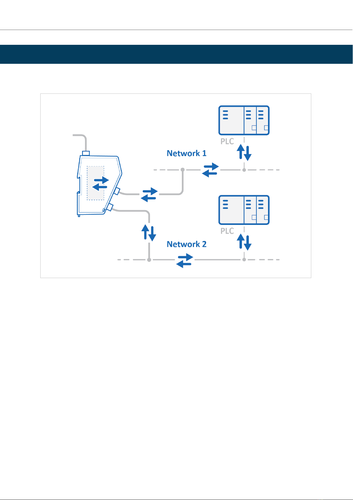
4.1. How the Communicaon Works .......................................................................................... 6
4.2. How the Data Exchange Works ............................................................................................ 7
4.3. Data Integrity .................................................................................................................. 7
5. Installaon ............................................................................................................................. 8
5.1. External Parts .................................................................................................................. 8
5.2. DIN Rail Mounng ............................................................................................................ 9
5.3. Connect to EtherNet/IP Network ........................................................................................ 10
5.4. Connect to Modbus TCP Network ....................................................................................... 11
5.5. Connect to Power ............................................................................................................ 12
5.6. Security Switch ............................................................................................................... 13
5.7. Lock the Cables ............................................................................................................... 15
5.8. DIN Rail Demount ............................................................................................................ 16
6. Communicator Conguraon ................................................................................................... 18
6.1. Connect the Communicator ............................................................................................... 18
6.2. Access the Built-In Web Interface From HMS IPcong ............................................................. 19
6.3. Access the Built-In Web Interface From a Web Browser .......................................................... 21
6.4. Communicator Built-In Web Interface Overview .................................................................... 22
6.5. EtherNet/IP Sengs ........................................................................................................ 23
6.5.1. EtherNet/IP IP Sengs .............................................................................................. 23
6.5.2. Connecon Sengs .................................................................................................. 25
6.6. Modbus TCP Sengs ........................................................................................................ 26
6.6.1. Modbus TCP IP Sengs ............................................................................................. 26
6.6.2. Timeout Time Sengs .............................................................................................. 28
6.7. I/O Conguraon ............................................................................................................ 29
6.8. Apply Conguraon ......................................................................................................... 33
6.9. Conguraon Notes ......................................................................................................... 34
6.9.1. Add Conguraon Note ............................................................................................ 34
6.9.2. View and Edit Conguraon Notes .............................................................................. 35
7. PLC Conguraon ................................................................................................................... 37
Anybus® Communicator™ - EtherNet/IP™ Adapter to Modbus TCP Server
SCM-1202-196 Version 1.0

7.1. Export Product EDS File .................................................................................................... 37
7.2. Addressing and Register Mapping ....................................................................................... 37
7.2.1. Data From Modbus TCP Network to Serial-Subnet .......................................................... 37
7.2.2. Data From Serial-Subnet to Modbus TCP Network .......................................................... 37
7.2.3. Idle Mode ............................................................................................................... 38
8. Verify Operaon ..................................................................................................................... 39
8.1. Communicator Status Monitor ........................................................................................... 39
8.2. Communicator LED Indicators ............................................................................................ 41
9. Maintenance ......................................................................................................................... 43
9.1. Conguraon File Handling ............................................................................................... 43
9.1.1. Export Conguraon ................................................................................................ 43
9.1.2. Import Conguraon ................................................................................................ 44
9.2. Clear and Revert Conguraon .......................................................................................... 45
9.3. Firmware Management .................................................................................................... 46
9.3.1. View the Firmware Version ........................................................................................ 46
9.3.2. Firmware and Conguraon Compability .................................................................... 46
9.3.3. Firmware File Validaon ............................................................................................ 46
9.3.4. Update Firmware ..................................................................................................... 47
10. Troubleshoong ................................................................................................................... 48
10.1. Diagnoscs ................................................................................................................... 48
10.1.1. I/O Data ............................................................................................................... 48
10.1.2. Event Log .............................................................................................................. 49
10.2. Reset to Factory Sengs ................................................................................................. 50
10.3. Firmware Upgrade Error Management ............................................................................... 52
10.4. Support ....................................................................................................................... 54
10.4.1. Support Package .................................................................................................... 54
11. Technical Data ...................................................................................................................... 55
11.1. Technical Specicaons ................................................................................................... 55
Anybus® Communicator™ - EtherNet/IP™ Adapter to Modbus TCP Server
SCM-1202-196 Version 1.0

1. Preface
1.1. About This Document
This document describes how to install and congure Anybus® Communicator™.
For addional documentaon and soware downloads, FAQs, troubleshoong guides and technical support,
please visit www.anybus.com/support.
1.2. Document Convenons
Lists
Numbered lists indicate tasks that should be carried out in sequence:
1. First do this
2. Then do this
Bulleted lists are used for:
• Tasks that can be carried out in any order
• Itemized informaon
User Interacon Elements
User interacon elements (buons etc.) are indicated with bold text.
Program Code and Scripts
Program code and script examples
Cross-References and Links
Cross-reference within this document: Document Convenons (page 1)
External link (URL): www.anybus.com
Safety Symbols
DANGER
Instrucons that must be followed to avoid an imminently hazardous situaon which, if not avoided,
will result in death or serious injury.
WARNING
Instrucons that must be followed to avoid a potenal hazardous situaon that, if not avoided, could
result in death or serious injury.
CAUTION
Instrucon that must be followed to avoid a potenal hazardous situaon that, if not avoided, could
result in minor or moderate injury.
IMPORTANT
Instrucon that must be followed to avoid a risk of reduced funconality and/or damage to the
equipment, or to avoid a network security risk.
Preface Anybus® Communicator™ - EtherNet/IP™ Adapter to Modbus TCP Server
SCM-1202-196 Version 1.0 Page 1 of 56

Informaon Symbols
NOTE
Addional informaon which may facilitate installaon and/or operaon.
TIP
Helpful advice and suggesons.
1.3. Trademarks
Anybus® is a registered trademark of HMS Networks.
All other trademarks are the property of their respecve holders.
Anybus® Communicator™ - EtherNet/IP™ Adapter to Modbus TCP Server Trademarks
Page 2 of 56 SCM-1202-196 Version 1.0

2. Safety
2.1. Intended Use
The intended use of this equipment is as a communicaon interface and gateway.
The equipment receives and transmits data on various physical layers and connecon types.
If this equipment is used in a manner not specied by the manufacturer, the protecon provided by the
equipment may be impaired.
2.2. General Safety
CAUTION
Ensure that the power supply is turned o before connecng it to the equipment.
CAUTION
This equipment contains parts that can be damaged by electrostac discharge (ESD). Use ESD
prevenon measures to avoid damage.
CAUTION
To avoid system damage, the equipment should be connected to ground.
IMPORTANT
Using the wrong type of power supply can damage the equipment. Ensure that the power supply is
connected properly and of the recommended type.
Safety Anybus® Communicator™ - EtherNet/IP™ Adapter to Modbus TCP Server
SCM-1202-196 Version 1.0 Page 3 of 56

3. Preparaon
3.1. Cabling
Have the following cables available:
• Ethernet cable for conguraon
• Ethernet cable x 2 for connecng to the networks
• Power cable
3.2. System Requirements
3.2.1. Supported Operang Systems
Operang System Descripon
Windows 7 SP1, 32-bit Windows 7 32-bit with Service Pack 1
Windows 7 SP1, 64-bit Windows 7 64-bit with Service Pack 1
Windows 10 64-bit Windows 10 64-bit
3.2.2. Supported Web Browsers
The Communicator built-in web interface can be accessed from the following standard web browsers.
• Google Chrome
•Microso Edge
• Mozilla Firefox
3.3. Mechanical Tools and Equipment
Have the following tools available:
• Flat-head screwdriver, size 5.5 mm
Needed when removing the Communicator from DIN-rail.
3.4. Support and Resources
For addional documentaon and soware downloads, FAQs, troubleshoong guides and technical support,
please visit www.anybus.com/support.
TIP
Have the product arcle number available, to search for the product specic support web page. You
nd the product arcle number on the product cover.
Anybus® Communicator™ - EtherNet/IP™ Adapter to Modbus TCP Server Preparaon
Page 4 of 56 SCM-1202-196 Version 1.0

3.5. HMS Soware Applicaons
Download the soware installaon les and user documentaon from www.anybus.com/support.
IPcong
Use the HMS soware applicaon IPcong and scan your network to discover and change the Communicator IP
address and to access the Communicator built-in web interface.
NOTE
As an alternave, you can set a stac IP address within the same IP address range as the
Communicator IP address on the computer accessing the Communicator built-in web interface.
NOTE
IPcong is only available for Windows.
3.6. Third-Party Soware Applicaons
Microso Excel, or equivalent soware applicaon that supports the Oce Open XML Workbook (xlsx) le
format. Needed to open and read the Event log le.
HMS Soware Applicaons Anybus® Communicator™ - EtherNet/IP™ Adapter to Modbus TCP Server
SCM-1202-196 Version 1.0 Page 5 of 56

4. About Anybus Communicator
4.1. How the Communicaon Works
Figure 1. Process data trac overview
The Communicator enables communicaon between a Master device connected to a EtherNet/IP network and a
Master device connected to a Modbus TCP network.
The Master device can, for example, be a PLC control system or a Gateway.
The Communicator main task is to transfer cyclic I/O data between the two networks.
Anybus® Communicator™ - EtherNet/IP™ Adapter to Modbus TCP Server About Anybus Communicator
Page 6 of 56 SCM-1202-196 Version 1.0

4.2. How the Data Exchange Works
Figure 2. The Communicator internal memory areas
The data exchanged between the Communicator and the EtherNet/IP and the Modbus TCP resides in the
Communicator internal memory buer.
The Communicator internal memory buer is divided into two areas: Input data and Output data.
Input Data
This Input data area is read by the Modbus TCP.
The Communicator can handle up to 1500 bytes input data.
Output Data
The Output data area is read/wrien by the EtherNet/IP.
The Communicator can handle up to 1448 bytes output data.
4.3. Data Integrity
A snapshot of the process data buer between the EtherNet/IP/Modbus TCP Client and the server interface is
used during the operaon of execung all the transacons within one cycle.
When the cycle is completed, the process data available on the server interface is updated and a new snapshot is
created for the next cycle.
How the Data Exchange Works Anybus® Communicator™ - EtherNet/IP™ Adapter to Modbus TCP Server
SCM-1202-196 Version 1.0 Page 7 of 56

5. Installaon
5.1. External Parts
Figure 3. External parts
A. Power connector
B. Label with LED designaon
C. Status LEDs
D. Conguraon port
E. EtherNet/IP port x 2
F. Modbus TCP port x 2
G. Cable e mount
H. Laser engraved connectors designaon
I. Security switch
J. Factory reset buon
K. Laser engraved label with product informaon
L. DIN rail locking mechanism
Anybus® Communicator™ - EtherNet/IP™ Adapter to Modbus TCP Server Installaon
Page 8 of 56 SCM-1202-196 Version 1.0

5.2. DIN Rail Mounng
IMPORTANT
The equipment must be electrically grounded through the DIN rail for EMC compliance. Make sure
that the equipment is correctly mounted on the rail and that the rail is properly grounded.
Figure 4. Aach the Communicator on the DIN rail
To aach the Communicator on the DIN rail:
1. Insert the upper end of the DIN rail clip into the DIN rail.
2. Push the boom of the DIN rail clip into the DIN rail.
DIN Rail Mounng Anybus® Communicator™ - EtherNet/IP™ Adapter to Modbus TCP Server
SCM-1202-196 Version 1.0 Page 9 of 56

5.3. Connect to EtherNet/IP Network
Figure 5. Connect to EtherNet/IP network
1. Connect the Communicator, upper connector, to your EtherNet/IP network.
EtherNet/IP Connector Pin Descripon
1 TD+
2 TD-
3 RD+
4 Not used
5 Not used
6 RD-
7 Not used
8 Not used
To Do Next
Connect the Communicator to the Modbus TCP network and to power.
Check LED status, refer to Communicator LED Indicators.
Anybus® Communicator™ - EtherNet/IP™ Adapter to Modbus TCP Server Connect to EtherNet/IP Network
Page 10 of 56 SCM-1202-196 Version 1.0

5.4. Connect to Modbus TCP Network
Figure 6. Connect to Modbus TCP network
1. Connect the Communicator, lower connector, to your Modbus TCP network.
EtherNet/IP Connector Pin Descripon
1 TD+
2 TD-
3 RD+
4 Not used
5 Not used
6 RD-
7 Not used
8 Not used
To Do Next
Connect the Communicator to the EtherNet/IP network and to power.
Check LED status, refer to Communicator LED Indicators.
Connect to Modbus TCP Network Anybus® Communicator™ - EtherNet/IP™ Adapter to Modbus TCP Server
SCM-1202-196 Version 1.0 Page 11 of 56

5.5. Connect to Power
CAUTION
Ensure that the power supply is turned o before connecng it to the equipment.
IMPORTANT
Using the wrong type of power supply can damage the equipment. Ensure that the power supply is
connected properly and of the recommended type.
Figure 7. Connect to power
1. Insert the cable wires to the terminal block and ghten the wire clamp screws.
Power port Pin Descripon
1 12-30 VDC Power Connector
2 Ground (GND)
3Funconal Earth (FE)
2. Connect the terminal block to the Communicator.
3. Connect the Communicator to a power supply.
4. Turn on the power supply.
To Do Next
Check LED status, refer to Communicator LED Indicators.
Anybus® Communicator™ - EtherNet/IP™ Adapter to Modbus TCP Server Connect to Power
Page 12 of 56 SCM-1202-196 Version 1.0

5.6. Security Switch
When the security switch is in its locked posion, the Communicator built-in web interface can not be accessed
and the Communicator can not be congured using the built-in web interface. Network specic parameters,
congured via the PLC is sll available.
To Lock and Unlock the Security Switch
Figure 8. Security switch in locked and unlocked posion
Use a pointed object, such as a ballpoint pen.
• To lock the security switch, push the toggle towards the Communicator front.
• To unlock the security switch, push the toggle towards the Communicator back.
Security Switch Anybus® Communicator™ - EtherNet/IP™ Adapter to Modbus TCP Server
SCM-1202-196 Version 1.0 Page 13 of 56

Security Switch Status LED
Figure 9. Security switch locked status LED
When the security switch is in its:
• locked posion, the security switch status LED turn solid green.
• unlocked posion, the security switch status LED is turned o.
Anybus® Communicator™ - EtherNet/IP™ Adapter to Modbus TCP Server Security Switch
Page 14 of 56 SCM-1202-196 Version 1.0

5.7. Lock the Cables
Figure 10. Lock the cables
To strain relieve the cables, place a cable e in the holder and lock the cables.
Lock the Cables Anybus® Communicator™ - EtherNet/IP™ Adapter to Modbus TCP Server
SCM-1202-196 Version 1.0 Page 15 of 56

5.8. DIN Rail Demount
Before You Begin
IMPORTANT
Be careful when removing the Communicator from the DIN-rail. If not removed properly, the DIN rail
locking mechanism and the product cover can break.
Have a at-blade screwdriver, size 5.5 mm, available.
Procedure
Remove the Communicator from the DIN Rail:
1. Insert the screwdriver into the Communicator DIN rail locking mechanism.
2. To unlock the Communicator DIN rail locking mechanism, turn the screwdriver clockwise.
Figure 11. Unlock the Communicator
Anybus® Communicator™ - EtherNet/IP™ Adapter to Modbus TCP Server DIN Rail Demount
Page 16 of 56 SCM-1202-196 Version 1.0
Table of contents
Other HMS Adapter manuals