SOHARD SH-ARC PCI User manual

Manual
SH-ARC PCI
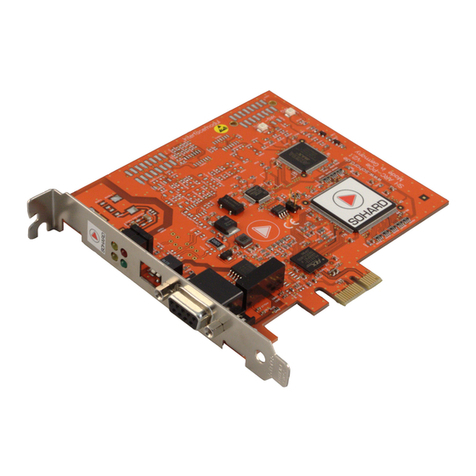
ARCNET - Adapter for the PCI Bus
Copyright by SoHard mbH, all rights reserved
V 01.00
/9/28/1998

SH-ARC PCI Manual Version 01.00
Contents
1 Introduction ...........................................................................................3
2 Features.................................................................................................3
3 Function.................................................................................................5
3.1 Network Interface Settings..............................................................5
3.2 Access..............................................................................................5
3.3 COM2002x Configuration.................................................................7
3.4 LED Indicators..................................................................................7
3.5 Dip Switch Settings..........................................................................8
4 Interfaces.............................................................................................10
4.1 Coax Interface ...............................................................................10
4.2 RS485 Interface ............................................................................10
5 Technical Specifications......................................................................12
5.1 eneral..........................................................................................12
5.2 ARCNET........................................................................................12
5.3 PCI Functionality............................................................................12
5.4 Coax Interface................................................................................12
5.5 RS485 Interface according AU ....................................................13
5.6 RS485 Interface, FARC E3 compatible.........................................13
6 Troubleshooting ..................................................................................14
7 Support................................................................................................15
8 References..........................................................................................15
9 Limited Warranty..................................................................................16
10 CE Declaration of Conformity ..........................................................17
11 INDEX................................................................................................18
page 2

SH-ARC PCI Manual Version 01.00
1 Introduction
The SH-ARC PCI is an ARCNET card for use in PCs with a PCI bus[4].
The controller used is the COM20020[1] or COM20022[2] (named below
COM2002x). The card features a 32-Bit data bus and thus, enables high
transfer rates. There are two ARCNET interfaces available although they
cannot be used at the same time.
2 Features
PCI Bus
•32 Bit Bus
•PCI 2.1 compatible
•PLX9052 chip by PLX
•PCI compatible mechanical assembly
•Mapping of the COM 2002x registers into the I/O space of the PC
RS485 Interface
•9-pin Sub-D connector
•Optically decoupled
•Bit rate 19.5 kBit/s - 10 MBit/s
•Integrated termination via dip switch
•Protective circuit
Coax Interface
•BNC jack
•Suitable for R -62 coax cable (93 Ohm impedance)
•Bit rate 2.5 MBit/s (10 Mbit/s, when transceiver is available)
•Protective circuit
ARCNET
•COM20020 or COM20022 controller
•Coax transceiver protected against invalid bitrate and mode
•LED for backplane mode on/off
•LED for ARCNET receiver activity
•LED for ARCNET transmitter activity
•LED for host access indication
•Automatic switchover between RS485 and coax interface
page 3

SH-ARC PCI Manual Version 01.00
Misce aneous
•DOS enabler for use under MS-DOS (register compatible to FARC E3
and other adapters equipped with the COM20020 controller)
•driver for Windows NT
•CE mark guarantees proper function in industrial environments (see
notes in chapter Interfaces/RS485 interface)
•optional: PC/104 add-on module
page 4

SH-ARC PCI Manual Version 01.00
3 Function
3.1 Network Interface Settings
The switchover from RS485 to coax and vice versa is effected
automatically. The RS485 interface is always active on the transmitter
side, so is the coax interface if the COM2002x is configured in an
appropriate way. Only one network line (coax or twisted pair cable) may
be connected at the same time.
3.1.1 Coax Interface
No manual settings are needed, but the interface is only activated if a
valid Bit rate (2.5 - 10 MBit/s) is selected and the controller COM2002x
is operated in Non-Backplane mode[1].
3.1.2 RS485-Interface
The termination can be turned on (S3, S4 ON) or off (S3, S4 OFF).
Default is ON. The COM2002x has to be operated in Backplane
mode[1].
The interface operates at all data rates.
3.2 Access
The SH-ARC PCI adapter is mapped automatically into the I/O or the
memory space by the BIOS of the host computer. The operating system
is able to retrieve start addresses and the interrupt used with the aid of
BIOS functions. The necessary parameters are:
page 5

SH-ARC PCI Manual Version 01.00
DEVICE ID = 0x9050h
VENDOR ID = 0x10B5h
CLASS CODE = 0x068000h
SUBSYSTEM ID = 0x00 (not used)
SUBSYSTEM VENDOR ID = 0x00 (not used)
Note: If there are any other PCI cards used in system, which use a PCI-
Parameter-combination identical to the one desciribed above, you have
to use card-specific information (i.e. serial number, controller type ) to
differentiate between the cards. Software routines written in C are
available on disk to read out this data.
For MSDOS a software is included which provides all necessary data in
form of an environment variable. For further information refer to the
Readme file on the floppy disk shipped with the adapter.
A Windows NT driver is included as well.
3.2.1 Address space
Following 4 address spaces are available:
PCI Base
Adress
Registers
LOCAL
SPACE
COM 20020 COM20022 Register
2 0 MEM / 16BIT / 512 Byte only COM2002x data
register
3 1 IO / 16 BIT / 16 Byte all COM2002x
registers in 2 byte
intervals
4 2 IO / 8BIT / 8 Byte all COM2002x
registers
5 3 MEM / 8BIT / 512 Byte only COM2002x data
register
Local Space 2[3] provides an interface compatible with all ISA bus
adapters equipped with the COM20020 controller.
Local Space 1 enables the use of the COM20022[2] 16-Bit mode. In the
COM20022 the 16-Bit mode is only implemented for the data register. All
other registers remain 8 Bits wide. For these registers the 8 high Bits are
insignificant during 16-Bit accesses by the host PC.
The Local Space 0 and 3 are intended for very fast data transfers from
PC to the SH-ARC PCI adapter. Please contact SoHard mbH if you
want to use this mode in your own applications. The Windows NT driver
already supports this operation mode.
page 6

SH-ARC PCI Manual Version 01.00
3.3 COM2002x Configuration
The COM2002x controller[1] has to be initialized in the following way:
3.3.1 Setup Register
Bit Description Bit No. Value Comment
Slow Arbitration
Bit
0 0 for Bit rate <=
2.5 MBit/s
1 for Bit rate >= 5
MBit/s
Pulse1 Mode 1 1 Push-pull driver
activated in backplane
mode
3.3.2 Access Mode
The COM2002x is operated in non-multiplexed mode. After a reset,
shifting to this mode is effected by controller unit accesses [1]
which have to be performed by the software. If this initia ization
is not performed, the COM2002x wi not function proper y.
In case of using the SoHard NT Driver or DOS Enabler, the
initialization is automatically performed.
3.4 LE Indicators
LED, PC Activity (red):
This LED indicates all I/O accesses to the SH-ARC PCI adapter by the
host PC. Every access is prolonged with the aid of a digital one-shot
page 7

SH-ARC PCI Manual Version 01.00
multivibrator (time constant of approximately 1 msec) and thus, made
visible.
LED, Coax Mode (green):
This LED is activated if the ARCNET controller is configured for a Bit
rate valid for the coax interface (2.5 MBit/s - 10 MBit/s), the controller is
transmitting and in default mode (= non Backplane). When the LED is
inactive, no data are sent via the coax interface. Note: The HIT is
specified only for operation at 2.5 Mbit/s.
LED, Receive (ye ow):
This LED indicates activity on the ARCNET receiver channel. The signal
is prolonged with the aid of a digital one-shot multivibrator and thus,
made visible. Because the signal is received again by both the coax
interface and the RS485 interface, the LED is also activated by the
transmitter signal. The LED continuously lights when the ARCNET is in
stable operation. The brightness depends on the Bit rate selected.
During reconfigurations [1] the LED periodically flickers.
LED Transmit (ye ow):
This LED indicates activity on the transmitter channel. The signal is
prolonged with the aid of a digital one-shot multivibrator and thus, made
visible. The brightness depends on the Bit rate selected, on the length of
the packets transmitted and on the number of connected ARCNET
nodes.
3.5 ip Switch Settings
The SH-ARC PCI Adapter is Plug & Play capable and does not provide
the possibility to select address or interrupt manually.
The only item with manually changeable settings is the RS485 interface.
There are four switches which can be accessed from outside.
S3 S4 Function Comment
ON ON Termination for RS485
enabled
Default setting
OFF OFF Termination for RS485
disabled
ON OFF invalid
OFF ON invalid
page 8

SH-ARC PCI Manual Version 01.00
S 1 S2 Function Comment
ON ON ND_RS and A ND
connected and wired to
ND_SEL
See chapter
„Interfaces“
OFF OFF ND_SEL not connected Default setting
OFF ON A ND wired to ND_SEL
ON OFF ND_RS wired to ND_SEL
A ND is the bracket potential. ND_RS is the ground of the
electrically decoupled RS485 circuit.
The pinning of the Sub-D Connectors is shown in chapter
„Interfaces“.
We recommend not to change the Default setting for S1 and S2.
page 9

SH-ARC PCI Manual Version 01.00
4 Interfaces
4.1 Coax Interface
Connector type: BNC jack, insulated
Pin Assignment:
Pin Description Meaning
1 Shield Shield of coax cable
2 Center Center of coax cable
4.2 RS485 Interface
There are two types of the SH-ARC PCI which differ in connector type
and pin assignment. Both are described below.
Important Notice: In order to meet the CE specifications, the cable
connected to the SUB-D connector/jack must have a shielding braid,
which has to be connected to the connector with low impedance.
4.2.1 RS485-Interface according AU (9 pin SUB-D male)
Assignment according AU standard[5]
Connector type: 9 pin SUB-D male
Pin Assignment :
Pin Description Meaning
1 ND_SEL Can be connected to A ND (S1=ON) and/or
ND_RS via S2. (see chapter Dip Switch
Settings)
2 nc Reserved for additional power supply
3 DATA-B Data line B (more negative than
DATA-A when in idle state)
4 nc Reserved for direction control
5 ND_RS Data reference potential, supply
6 +5V_RS Isolated +5V Suppy for RS485 Interface. The
maximum Current must not exceed 25 mA.
7 nc Reserved for additional power supply
8 DATA-A Data line A (more positive than DATA-B when in
idle state)
9 nc Reserved for additional power supply
Shield A ND Shield
A ND is the bracket potential. ND_RS is the ground of the
electrically decoupled RS485 circuit.
page 10

SH-ARC PCI Manual Version 01.00
4.2.2 RS485-Network Interface (9 Pin SUB-D female)
Assignment compatible to FARC E3 ARCNET adapter by SoHard.
Connector type: 9 pin SUB-D female
Pin Assignment:
PIN Description Meaning
1 ND_RS Data reference potential, supply
2 nc reserved
3 DATA-A Data line A (more positive than DATA-B when in
idle state)
4 DATA-B Data line B (more negative than
DATA-A when in idle state)
5 ND_SEL Can be connected to A ND and/or ND_RS.
(see chapter Dip Switch Settings)
6 nc reserved
7 nc reserved
8 nc reserved
9 +5V_RS Isolated +5V Suppy for RS485 Interface. The
maximum current must not exceed 25 mA.
Shield A ND Shield
A ND is the bracket potential. ND_RS is the ground of the
electrically decoupled RS485 circuit.
page 11

SH-ARC PCI Manual Version 01.00
5 Technica Specifications
5.1 General
Temperature range (operation): 0°C to +55°C
Temperature range (storage): -20°C to +85°C
Power consumption: < 10W
Dimensions (without connectors): width 125mm, height 21 mm, depth
175mm
Weight: max. 0.5 kg (incl. packaging)
5.2 ARCNET
Compatibility: ANSI/ATA 878.1
Data rates: 19,531/ 39,063/ 78,125/ 156,25/
312,5/ 625 kbps
1.25 / 2.5 / 5 / 10 Mbps
5.3 PCI Functionality
Compatibility: PCI 2.1
Power supply: +5V/-12V
5.4 Coax Interface
Data rate: 2.5 Mbps
Input impedance: >= 10 kOhm( with f= 5 MHz)
Output voltage: min. 16Vss on terminated 93Ohm line
Output signal shape: Sinus Dipuls 200ns according
ANSI/ATA 878.1
Cabling: R 62 with Z=93Ohm recommended
Connector: BNC jack, insulated
page 12

SH-ARC PCI Manual Version 01.00
5.5 RS485 Interface according AUG
Compatibility: AU (Arcnet User roup)[5]
Data rate: 19.5 kbps bis 10Mbps
Input level threshold +/- 200mV
Polarity idle level: positive
Input impedance: via dip switch configurable, approx. 150
Ohm (with DC-Biasing)
DC-Biasing: configurable via dip switch 390Ohm
+5V/390Ohm 0V
Transmission level: min +/- 3,0V
Connector: 9 pin SUB-D connector
5.6 RS485 Interface, FARC E3 compatible
Compatibility: FARC E3 ARCNET Adapter by SoHard
Data rate: 19.5 kbps to 10Mbps
Input level threshold: +/- 200mV
Polarity, idle level: positive
Input impedance: via dip switch configurable, approx. 150
Ohm (with DC-Biasing)
DC-Biasing: configurable via dip switch 390Ohm
+5V/390Ohm 0V
Diff. Transmission level: min +/- 3,0V
Connector: 9 pin SUB-D jack
page 13

SH-ARC PCI Manual Version 01.00
6 Troub eshooting
•Adapter is not mapped into the PC Address Range.
Possible Cause: The computer BIOS does not support the required
hardware mechanism (The PCIBIOS program, shipped with the
adapter, reports for "Hardware Mechanism" a value unequal 1 or 11).
Solution: Update the BIOS
•Adapter is accessib e, but no Interrupts are generated.
Possible cause: An insufficient number of interrupt lines is reserved for
PCI in the computers BIOS setup. (The PCIBIOS program, shipped
with the adapter, reports for "Interrupt" the value 0) Solution: Configure
more interrupts for PCI in the BIOS setup.
•Transmission Activity LED indicates Reconfigurations.
Possible causes:
- Only one node is present in the network
- The network is not properly terminated
- At RS485 connections DATA-A and DATA-B are exchanged
•Green LED does not ight
Possible causes:
- The COM2002x is operated at an invalid Bit rate
- The COM2002x is in backplane mode
- The COM2002x is not acitvated on the transmitter side
page 14

SH-ARC PCI Manual Version 01.00
7 Support
If you experience any problems during adapter setup or operation please
refer to the chapter "Troubleshooting" before contacting SoHard.
SoHard mbH
Bussardstr. 19
90766 Fürth
ermany
Tel: +49 (0)911 97341 - 0 (central office)
- 522 (technical support)
Fax: +49 (0)911 97341- 510
eMail: support@sohard.de
http://www.sohard.de
8 References
Reference Document
[1] Data Sheet COM20020, SMC, dated May 25th, 1997
[2] Data Sheet COM20022, SMC, dated March, 21st
1997
[3] Data Sheet PCI 9052, PLX, Rev 1.0
[4] PCI Local Bus Specification 2.1
[5] AU (Arcnet User roup) ARCNET Hardware
Manual
[6] Data Sheet Serial EEPROM NM93CS46N, April
1996, NATIONAL SEMICONDUCTOR
page 15

SH-ARC PCI Manual Version 01.00
9 Limited Warranty
SoHard mbH warrants that every product and all components are free
from defects in workmanship and materials under normal use and
service. The warranty period is one year from the date of purchase. The
warranty is limited to the original purchaser and cannot be transferred.
If a product does not operate as warranted during the applicable
warranty period, SoHard mbH shall, at its option, repair the defective
product or component or deliver to the customer an equivalent product
or component. Repaired or replaced products or components are
delivered in exchange of the defective products or components with the
option of SoHard mbH whether the delivered products or components
are new or as new. All products that are replaced will become the
property of SoHard mbH.
This limited warranty excludes damage due to accidents, catastrophes,
negligence, inadequate use or changes of the product or component
made by the customer.
Warranty service may be obtained by delivering the defective product or
component accompanied by a copy of the dated proof of purchase, to
SoHard mbH. It has to be ensured that the package is appropriate for
safe shipment. After expiration of the warranty period (one year from the
date of purchase) no warranty services can be obtained whatsoever.
The repaired or replaced item will be shipped to the customer. Carrier
and terms of shipment are concern of SoHard mbH. If there are special
requirements of the customer in terms of shipment or a destination
outside of ermany, Austria, Switzerland and the eastern european
countries the shipment will be carried out at the expense of the
customer.
The warranty described above is the only warranty SoHard grants for ist
products. There is no warranty, neither explicit nor implicit, that SoHard
mbH products can be used commercially, the usability for specific
applications or that third party rights are not violated. SoHard mbH
makes no warranty that the operation of a accompanying software will
be uninterrupted and error free. SoHard mbH shall not be responsible
whatsoever for damage by chance, special or intentional damage and
costs and failures due to the use and operation of the product, covered
by this warranty.
(Some governments don’t allow the disclaim for damage by chance or
subsequent damage in connection with this type of product. In this case
above limitations are void.)
page 16

SH-ARC PCI Manual Version 01.00
10 CE Dec aration of Conformity
DECLARATION OF CONFORMITY
According to ISO/IEC uide 22 and EN 45014
Name of Supplier: SoHard GmbH
Address of Supplier: Bussardstr. 19
D-90766 Fürth
Germany
declares that the Product
Product name: SH ARC PCI
Product Type: SH ARC PCI
is in confirmity with the following product specifications:
Safety: EN60950: 1992
+ A1: 1993 + A2: 1993
+ A3: 1995 + A4: 1997
EMC: EN 50081-2: 1994-03
EN 50082-2: 1997-11
Fürth, 21.09.1998 ___________________________________
(Wolfgang rund, Managing Director)
page 17

SH-ARC PCI Manual Version 01.00
11 INDEX
9
93Ohm 12
A
Addresses 15
ANSI 12
ARCNET Functionality
12
ATA 878.1 12
AU 10, 11
B
Backplane-Mode 5
BNC 12
C
Cabling 12
CE Specifications 10
CLASS CODE 6
COAX 5, 12
COAX-Interface 10
COM20020 15
COM20022 15
Compatibility 12
Connector 13
D
Data Rate 12
DATA-A 10
DATA-B 10
DC-Biasing 13
DEVICE ID 6
Dimensions 12
Duplex 13
E
eMail 15
F
Features 3
I
Idle Level 13
Input Impedance 12, 13
L
LED 7
LOCAL SPACE 6
M
MSDOS 6
N
Network Interface
Settings 5
Non-Multiplexed-Mode
7
O
Output Signal Shape 12
Output Voltage 12
P
PCI BaseAdres
Register 6
PCI-Funktionality 12
Pin Assignment 10
Polarity 13
Power Consumption 12
Protective round 10
S
Setup Register 7
Shield 10, 11
SoHard mbH 15
SUB-D connector 10
Support 15
T
Technical Support 15
Terminating Resistor 12
Termination 5
Transmission Level 13
V
VENDOR ID 6
W
Weight 12
page 18

SH-ARC PCI Manual Version 01.00
page 19
Table of contents
Other SOHARD Adapter manuals
