manuals.online logo
Brands
  1. Home
  2. •
  3. Brands
  4. •
  5. Hobbywing Technology
  6. •
  7. Accessories
  8. •
  9. Hobbywing Technology G3 Advance Gyro User manual

Hobbywing Technology G3 Advance Gyro User manual

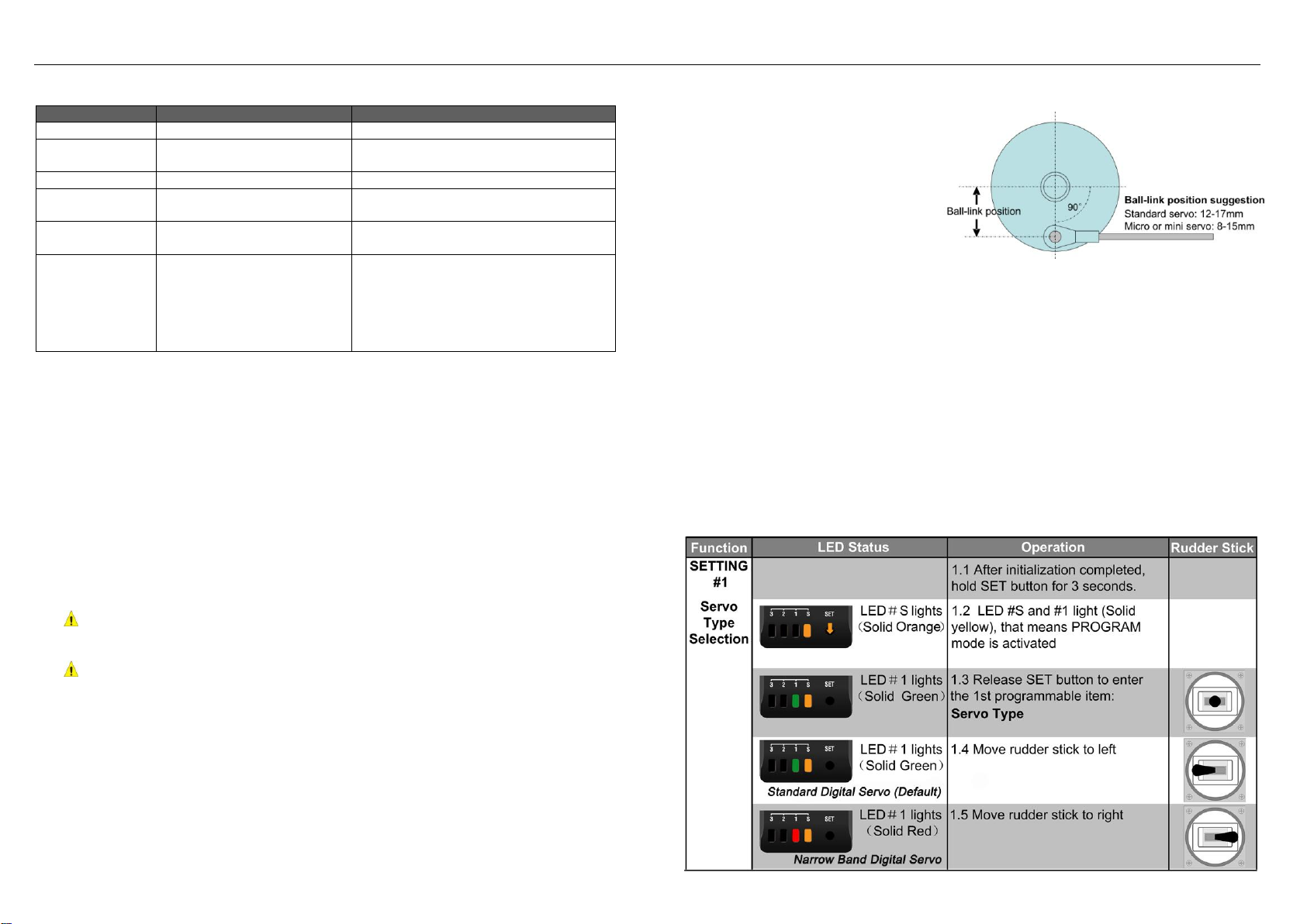
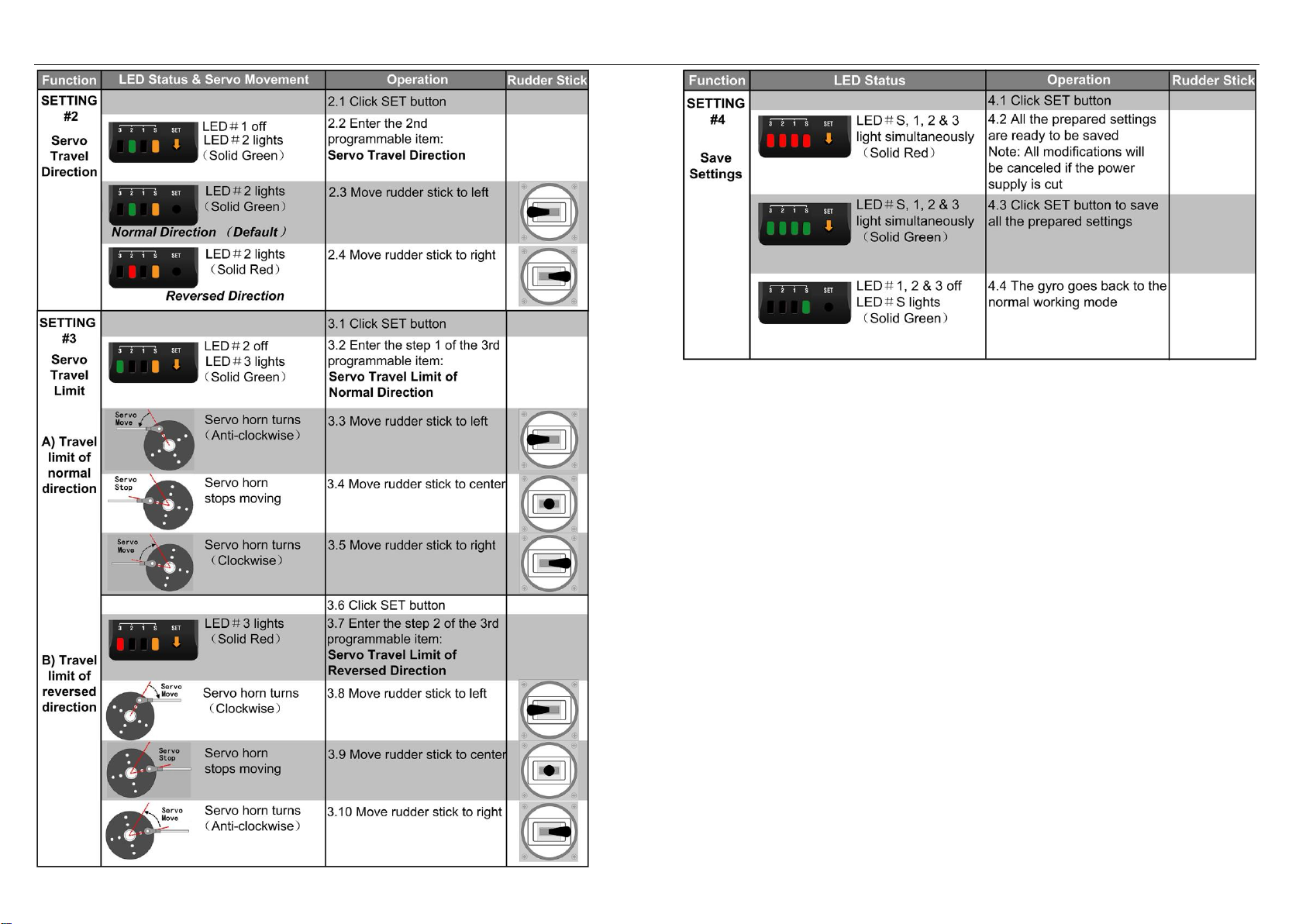
User Manual of Gyro VER: HW-100-G3 ADV-20111228 Page 1 of 4
【FEATURES】
1. This Gyro uses advanced MEMS (Micro Electro Mechanical Systems) angular rate
sensor and AVCS (Angular Vector Control System) algorithm. It is a super performance,
compact, light weight gyro developed for model helicopter.
2. Built-in temperature compensation provides high-precision direction control ability to
eliminate the drift caused by environment temperature changing.
3. Dual working mode: Normal Mode and Head-Lock Mode, switched by the sensitivity
value of the GAIN channel of your transmitter.
4. The program process is completely digitalized to make the gyro more reliable. Each
programmable value is adjusted by a “SET”button without any analog component such
as trimming potentiometer.
5. Compatible with standard (333Hz) and narrow band (560Hz) digital servos.
【SPECIFICATION】
1. Dimension: 26mm * 24mm * 9mm
2. Weight: 12g (wires and connectors included)
3. Operating voltage DC 4.5-6.5V, operating current ≈ 50mA, maximum current <100mA
4. Servo: Standard digital servos (frequency 333Hz), servo neutral point: 1520us
Narrow band digital servos (frequency 560Hz), servo neutral point: 760us
This gyro cannot work with analog servo!
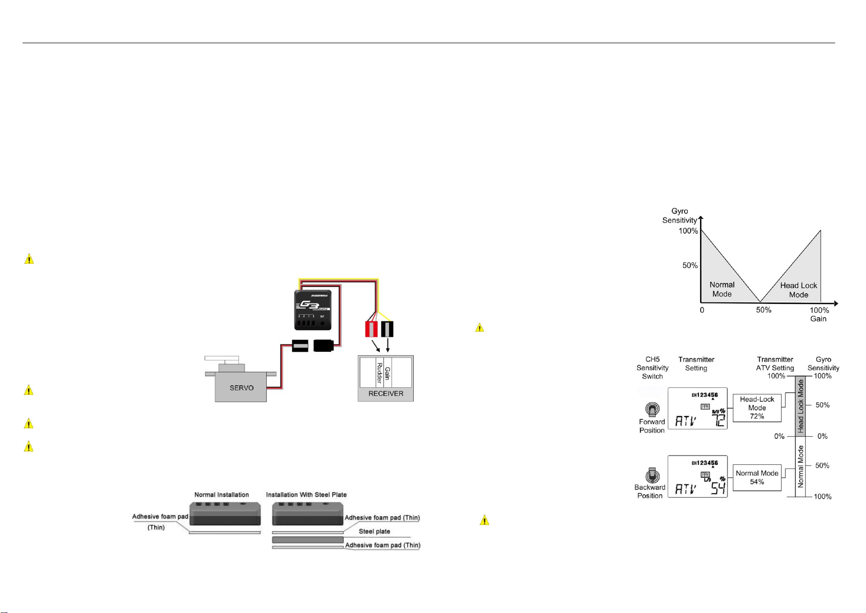
【WIRING】
1. Connect the rudder servo lead to the
female connector on the gyro.
2. There are 2 male leads coming from
the gyro, the lead with black, red
and white wires is plugged into the
Rudder channel of your receiver,
and the lead with one single orange
wire is plugged into the Gain
channel of your receiver.
For Futaba receiver, Rudder
channel is located in channel 4 (CH4)
and Gain in channel 5 (CH5).
For JR receiver, Rudder channel is located in channel 3 (CH3) and Gain channel in
AUX2.
For other remote control systems, please read their user manuals for reference.
【GYRO INSTALLATION】
Please install the gyro
close to the centre of
fuselage and keep
away from vibration.
Please don’t install the
gyro close to heat
generation sources, or
strong electromagnetic
interference sources, or high vibration sources such as motor, speed controller, etc.
To isolate the vibration to the gyro, a soft foam pad should be attached on the bottom of the
gyro. If helicopter tail drifts during flight, please check the vibration source of fuselage and
install the metal plate (package included) for high frequency vibration isolation purpose.
【SPECIAL HINTS FOR INSTALLATION ON NITRO-POWERED HELICOPTER】
Please Install and handle with care. If tail drifts, please use the following methods for trouble
shooting.
1. Install the steel plate, and try difference thickness of foam tape pads. In general, using
thinner foam pads can provide better performance.
2. Carefully fasten the gyro wires to avoid extra vibrations affect gyro performance.
3. After the above operations, run the engine under idle speed and touch the gyro case to
test vibration. If no obvious vibration conducted to gyro, which means the installation is
successful.
【START TO USE】
1. Turn on transmitter and ensure the output
signal is in good condition.
2. Set the GAIN value above 50% in
transmitter to select Head-Lock Mode.
3. Keep the rudder stick at neutral position,
and then power on the gyro (That means
connecting the battery pack to the speed
controller to supply the receiver, then the
gyro gets its power supply from the receiver).
Don’t move the rudder stick or the helicopter
until the initialization process is completed.
Gyro cannot work properly if it is not initialized with Head-Lock Mode.
4. Some old transmitters (such as Futaba FF7S, FF6S and T6XHS, etc) haven’t the gyro
sensitivity switching function, in such
a case, the gyro sensitivity setting is
performed by adjusting the ATV of
the GAIN channel, and the mode
switching of Head-Lock Mode and
Normal Mode is performed by the
switch position.
The figure is an example of
sensitivity setting with a T6XHS
transmitter. In the hovering flight,
(That is: Head-Lock Mode), the gyro
sensitivity is set to 72%, and in the
Idle-up flight (That is: Normal Mode),
the gyro sensitivity is set to 54%.
The Head-Lock Mode and Normal
Mode are switched by the CH5 switch position.
Please always keep in mind that when the sensitivity switching is performed with
the ATV setting, the Head-Lock Mode cannot be used at both side (that means forward
position and backward position) of the CH5 switch for hovering and Idle-up flight.
User Manual of Gyro VER: HW-100-G3 ADV-20111228 Page 2 of 4
【LED STATUS】
Under different working mode, the LEDs on the gyro have different status.
【SET-UP PROCEDURE】
The installation and set-up process of the gyro are almost same as other brand products. For
a better performance, please read the following instructions.
1. Select the type of digital servo (333Hz or 560Hz) correctly before connecting the tail
servo to avoid permanent damage.
2. Turn on transmitter and ensure the GAIN channel sensitivity is more than 50% (that
means the gyro will work in Head-Lock Mode). Put the rudder stick, trimmer and sub-trim
at neutral position.
3. Connect the rudder servo to the gyro; switch on the main power, the gyro starts
initialization. When the initialization is completed, LED #S lights solid green means the
gyro is working in Head-Lock Mode, while solid red means the gyro is working in Normal
Mode. Please reverse the direction of GAIN channel if the gyro is working in Normal
Mode.
4. Move the fuselage clockwise and anti-clockwise to check the rudder servo horn moving
direction. If wrong direction occurred, please program the gyro correctly.
This is an important operation!
5. Move rudder stick left and right to check the rudder servo horn moving direction. If wrong
direction occurred, please program the gyro correctly.
This is an important operation!
6. After the above procedures, disconnect the main battery pack to power-off the gyro and
then reconnect the battery pack after a few seconds. Check the gyro again to ensure the
LED #S is solid green after initialization.
7. In Head-Lock Mode, make the rudder servo neutrally, and then install the servo horn
perpendicular to servo body.
8. Adjust the length of push-rod linkage to achieve stable hovering in the normal mode.
9. Follow the program instructions to adjust the rudder servo travelling limits of left and right
side.
10. During the test flight, establish a stable hovering by adjusting the sensitivity value of gain
channel. The suggested value should around 65% to 70%, the most suitable value is
gotten by test flights adjustment. If there is any tendency for the tail to twitch quickly from
side to side, it will be necessary to lower the gain value. If the tail is precarious when
pitch and throttle is rapidly changed, please use higher gain value.
If you do need to use normal mode,
please switch to normal mode after
the gyro completes the initialization
in head-lock mode.
The picture at right side shows the
rudder servo in neutral position.
Please try your best to have a 90
degree angle as the picture
shows.
【IMPORTANT NOTES】
1. Carefully check the servo type before connecting it to gyro.
2. Please place the fuselage to the flying field for a few minutes before flight. It can let the
gyro to accommodate the environment temperature for best performance.
3. Carefully fasten the gyro wire and remain extra length to avoid extra vibration
4. Carefully check the rudder servo to maintain good condition
5. When the Gyro Is interfered accidentally, the LED #S will change to Orange color and
flash slowly, the gyro will quickly resume to working status to avoid crash. Normally, the
resuming time <100ms. After landing, please click the “SET”button to clear the LED #S
alarm. Please check the wiring, the flying field circumstance and the battery carefully to
search for the reason of interference before the next flight.
6. Please adjust the rudder channel travel range (ATV) at both left and right side to get
better symmetry and linearity.
7. Carefully check all the settings, data and connections before flight to avoid any accident.
【PROGRAM THE GYRO】
The gyro can be user-programmed by using the rudder stick of transmitter.
Working Modes
Rudder Stick Conditions
LED Status
Head-lock Mode
Neutral point
LED #S: Solid green
Head-lock Mode
Stick not at neutral position
or initialization failed
LED #S: Green, rapidly flashes 2 times
Normal Mode
Neutral point
LED #S: Solid red
Normal Mode
Stick not at neutral position
or initialization failed
LED #S: Red, rapidly flashes 2 times
Failure
No radio signal or
initialization failed
LED #S: Orange, slowly flashes
Gyro
initialization
Keep rudder stick at neutral
position and ensure fuselage
steady
All LEDs light, red for 0.5 second then
turn to green for 1 second, then LED #1,
#2, #3 turn-off, LED #S solid green. If
initialization failed, LED #1, #2 and #3
become solid green, and LED #S
flashes slowly with Orange color.
User Manual of Gyro VER: HW-100-G3 ADV-20111228 Page 3 of 4
【RESET ALL THE PROGRAMMABLE ITEMS TO DEFAULT】
1. Start up the gyro and let it finish the initialization, after that, hold the SET button until the
LED #S changes to orange and LED #3 changes to green;
2. Release the SET button, LED #3, #2, #1 change to red, LED #S changes to orange;
3. Click the “SET”button, the LED #S changes to red;
4. If you want to reset all the programmable items to default, please click “SET”button
again, all 4 LEDs change to green, and then the gyro restarts immediately. If you want to
keep the current settings, please power off the gyro to cancel the reset operation.
【INITIALIZATION THE GYRO IN WORKING STATUS】
1. Reset the rudder servo to neutral position: Shake the rudder stick left and right at least 4
times at an interval of 1 second. (The traveling range should be at least half of the full
range)
2. Reset the neutral date of Head-Lock Mode: Move the rudder stick to the neutral position,
switch the transmitter sensitivity switch between Head-Lock Mode position and Normal
Mode position at least 3 times at an interval of 1 second or less, then set the switch to
the Head-Lock Mode position.
【NONRESPONSIBILITY DECLARATION】
R/C flight has potential danger. We have tried our best to use the good quality components
and high technologies to provide superior performance. But for the unpredictable
environment and conditions, customers are also suggested to try their best to maintain proper
installation and operation, ensure power supply and control signal are stable and believable,
flight in legal flying field. In that we have no control over the correct use, installation,
application, or maintenance of our products, no liability shall be assumed nor accepted for
any damages, losses or costs resulting from the use of the product. Any claims arising from
the operating, failure of malfunctioning etc. will be denied. We assume no liability for personal
injury, consequential damages resulting from our product or our workmanship. As far as is
legally permitted, the obligation to compensation is limited to the invoice amount of the
affected product.
User Manual of Gyro VER: HW-100-G3 ADV-20111228 Page 4 of 4
【USER MEMO】

Popular Accessories manuals by other brands

Panasonic EX-F70 SERIES Ordering guide

Panasonic

Panasonic EX-F70 SERIES Ordering guide

Velleman CTC1000WS user manual

Velleman

Velleman CTC1000WS user manual

Red Arrow PC10A installation instructions

Red Arrow

Red Arrow PC10A installation instructions

Polygroup SUMMER WAVES 3D instructions

Polygroup

Polygroup SUMMER WAVES 3D instructions

Louroe AP-8-RM Installation and operating instructions

Louroe

Louroe AP-8-RM Installation and operating instructions

Lord MicroStrain SG-Link-LXRS Technical notes

Lord MicroStrain

Lord MicroStrain SG-Link-LXRS Technical notes

Denver ASA-60 manual

Denver

Denver ASA-60 manual

aci IMMERSION SERIES Installation & operation instructions

aci

aci IMMERSION SERIES Installation & operation instructions

Everest EBC37 owner's manual

Everest

Everest EBC37 owner's manual

Fetco Extractor CBS-2051 Technical bulletin

Fetco

Fetco Extractor CBS-2051 Technical bulletin

Lorex VQ2120 Specifications

Lorex

Lorex VQ2120 Specifications

ARoma trick A-Trick 100 Classic user guide

ARoma trick

ARoma trick A-Trick 100 Classic user guide

GTO FM130 installation manual

GTO

GTO FM130 installation manual

NUTRICHEF PKESPR26 user manual

NUTRICHEF

NUTRICHEF PKESPR26 user manual

Omron ZX-E - Operation manual

Omron

Omron ZX-E - Operation manual

WICKEDedge Field & sport instruction manual

WICKEDedge

WICKEDedge Field & sport instruction manual

Philio Z-Wave PHI PSM02 quick start guide

Philio

Philio Z-Wave PHI PSM02 quick start guide

Polar Electro Y6 user manual

Polar Electro

Polar Electro Y6 user manual

manuals.online logo
manuals.online logoBrands
  • About & Mission
  • Contact us
  • Privacy Policy
  • Terms and Conditions

Copyright 2025 Manuals.Online. All Rights Reserved.