Hochiki TCH-B100 User manual

Hochiki America Corporation
7051VillageDrive,Suite100•BuenaPark,CA 90621-2268
Phone:714/522-2246 • Fax:714/522-2268
Find latest revision at www.hochiki.com
TCH-B100HAND-HELDPROGRAMMER
PRODUCTPARTS
• 9 Volt Battery
• Remote Programming Cables
STANDARD FEATURES
•Compactunit
•Easy to use
•Providesaddresssettingandreading
•Can be used on both sensors and modules
•Has the diagnostic ability to display the
analogvalue
•Over8000addresssettingsfromonebattery.
1.Installsensorontoprogrammer,ensuringthat
sensor protrusions align with programmer grooves.
2. Press the left gray button to switch programmer on.
Abattery check message will appear followed by
the device's address (Unprogrammed sensors will
read address 127).
3. Set the required address by incrementing the left
and right gray buttons (the display will show three
red flashing dots if the address being programmed
is different from the device's current address).
4. When the desired address is present, press the red
button to store that address. The three red dots on
the display will no longer be present.
ADDRESS SETTING:
SPECIFICATIONS
Rated Voltage: 9 VDC
Battery: 9 VDC
Weight: 0.34 lbs
Length: 6 1/4"
Color: White
APPLICATION
TCH-B100isdesignedforusewithallanalogsensors
andmodules.
Continued on back

Specificationssubjecttochangewithoutnotice.
HochikiAmericaCorporation • TCH-B100Hand-HeldProgrammer
TESTING A SENSOR
Note:Ionizationsensorsrequirea30secondstabilizationperiodbeforeanalogvaluereadingshouldbetaken.
1. Installthesensor and power up programmer as previously describedonpage 1
2. Press the “Red” button.An “A” will appear on the display followed by the analog value. The
value will be continuously updated for three minutes
3. The“ALG’photoelectricsensorshouldhaveavaluedisplayedofbetween56-63.The“AIE”
ionization sensor should have a value displayed of between 52-73.
Values out of these ranges indicate that the sensor chamber has become contaminated. Refer to technical
bulletin“HA-96”forproperservicinginstructionsorreturnsensortofactoryforservicing.
DISPLAY MESSAGES:
bAt- On upon power up (battery check). Also on when battery is low. Low battery good for up to 3,000
address setting operation.
E0 -Attempting to set an address beyond 127.
E1-Attemptingto program an address with no deviceconnected.
E2-Cannotfinddevice after power up.
E3-Invalid sensor response.
E4-Cannotfindthedeviceprogram.
E5- Device readerror.
E6- Fail duringAnalog valuereading
PROGRAMMING BUTTONS:
LEFT GRAY BUTTON Power on. Automatically reads the addresss of a sensor.
Subsequent operations will advance the device address by ten.
RIGHT GRAY BUTTON Power off. Advances the device address by one.
RED BUTTON Stores the displayed address to the device and is used to read sensor analog
levels.
NOTE: Prior to programming, ensure battery is connected.
Programming Buttons Display
Remote Programming
Jack
Remote Programming Cable
(DCP-FRCME-S)
Remote Programming Cable
(All Modules except DCP-FRCME-S)
To Remote
Programming Jack

Hochiki America Corporation
7051VillageDrive,Suite100 • Buena Park, CA 90621-2268
Phone: 714/522-2246 • Fax: 714/522-2268
PRODUCT PARTS
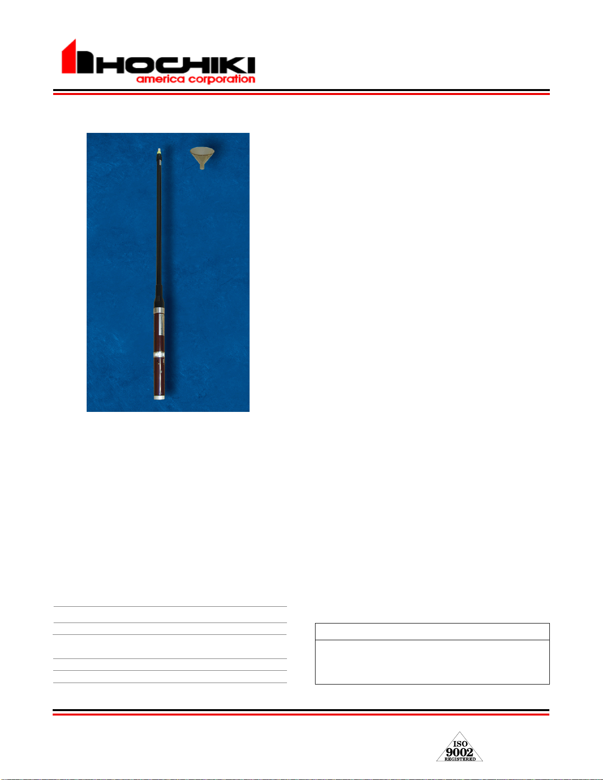
•TSE-A100Self-Contained Smoke Generator
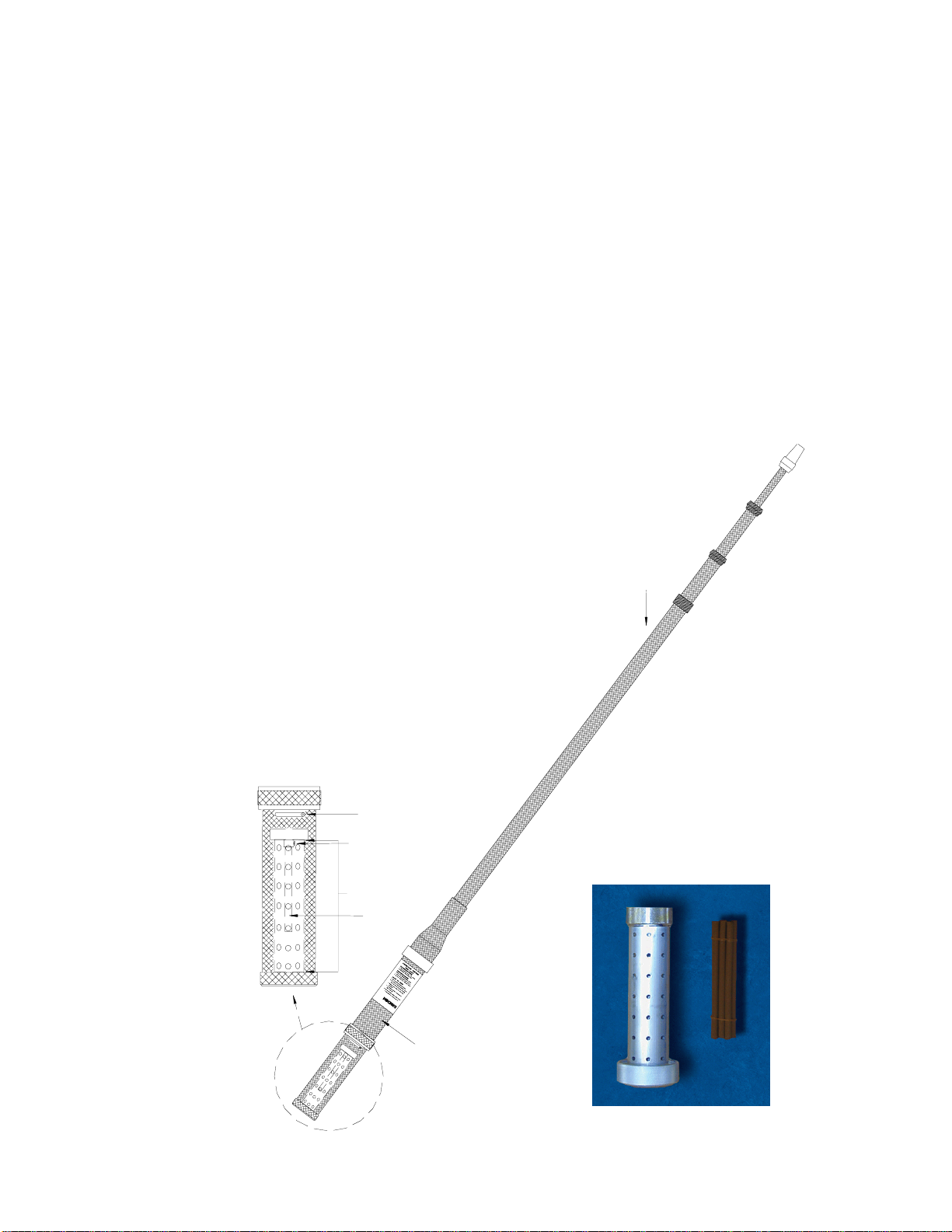
• Punk Stick (Part No. TSE-P100)
APPLICATION
The Hochiki America TSE-A100 is one of the most
advanced units of its kind and is the result of extensive
research and development aimed at making the job of
testing detectors a simple and efficient operation .
The TSE-A100 can be used to test all types of smoke
detectors by applying smoke from an internal smoke
source.
Although this is not a calibrated amount of smoke, the
TSE-A100 is an excellent choice for periodic functional
testing of smoke detectors.
OPERATION
Testing a Detector
Onceyou havepreparedtheTSE-A100,follow thesteps
in this section to test smoke detectors.
NOTE:
Allow 30 to 60 seconds after igniting punk stick
for sufficient smoke generation.
TSE-A100SELF-CONTAINED SMOKE GENERATOR
Specifications subject to change without notice.
SPECIFICATIONS
RatedVoltage 3VDC
Battery 2 - "D" Batteries
CombustionMaterial Punk Stick
(7 mm diameter, 150 mm long)
Weight 5 Lbs.
Length 5.25 to 14.1 feet
Color Brown
•Tests all types of smoke detectors.
•Completelyselfcontained and portable.
•Extends from 5.25 feet to 14.1 feet.
•InternalSmokeSource.
•Non-ToxicSmokeSource.
•Unit includes shoulder sling carrying case.
•Optionaladapterfor high velocity conditions.
•Exhaust function to clear detector.
•Built-infiltertoprevent tar residue from adhering to
thesurfaceofthe detector.
Continued on back
Preparation
1. RemovetheTSE-A100fromitscarryingcase.
2. Unscrew the combustion chamber from the
bottom of theTSE-A100.
3. Unscrew the punk stick holder retainer from
thecombustionchamber.
4. Insert a punk stick into the punk stick holder in
thecombustionchamber.
5. Light the punk stick with a flame.
6. Reassemblethecombustion chamber.
7. Screw the combustion chamber back into the
bottomof theTSE-A100
8. Extend the telescopic pole of the TSE-A100 to
a length which enables you to reach the
detector you wish to test.
STANDARD FEATURES

Specifications subject to change without notice.
HochikiAmericaCorporation•TSE-A100
OPERATION,
continued
Punk Stick Holder Retainer
Instruction Label
Combustion Chamber
Punk Stick
Power Indicator Screw
Telescopic Pole
NOTE
1. Use only the filter and combustion material
specified.
2. Check battery capacity before use to assure
efficientoperation.
3. Removebatteries beforelong-periodstorage.
Storing the TSE-A100
1. Rotate the combustion chamber to the #1
positiontoturnthe power off.
2. Compress the telescopic pole to its shortest
length.
3. Replace the TSE-A100 in its carry case.
4. Store in a cool, dry place.
5. Forextendedstorage, remove the batteries.
Testing a Detector,
continued
1. Rotate the combustion chamber so the #2
arrow line sup with the power indicator screw.
Thefanpowerson and a steady flow of smoke
is released from the tip of the TSE-A100.
2. Raise the extended tip of the TSE-A100 to
within6-8'ofthe detector. Thedetectorshould
alarm.
If no smoke comes out, check to make sure the
punk stick is ignited, and the power indicator on
the combustion chamber is set to #2.

Hochiki America Corporation
7051VillageDrive,Suite100 BuenaPark,CA 90621-2268
Phone:714/522-2246 Fax:714/522-2268
Find latest revision at www.hochiki.com
F044
Dimensions Pole extends to 15'
Material Stainless steel with easy grip
blackhandle
NSRT / NSTT
SMOKEDETECTOR REMOVALTOOL / TESTER
Specifications subject to change without notice.
NSTT-A100 WITH 15' POLE
(COMPLETE)
NSTT HEAD
SPECIFICATIONS
NSRT HEAD
STANDARD FEATURES
NSRT
• Combinationremoval tool/outercover removaltool
forAIE,ALG,SIJ,andSLR-24/-835 series sensors/
detectors.
• Choose either a Hand held or 15’ stainless steel
extension pole with easy grip black handle.
NSTT
• TestsHochikiAmerica SIJ-24 andSLR-24/-835
series smoke detector with a reed switch.
• Choose either a Hand held or 15’ stainless steel
extension pole with easy grip black handle.
• Nocombustion material needed.
• Nometer, batteries, orscrewdriverrequired.
• Meetsoutlined requirements in the NFPA72,
Inspection,Testing andMaintenance, Chapter 10.
NSRT-A100 WITH 15' POLE
(COMPLETE)
Detector Tester/Removal Tool
Dimensions NSRT HEAD: 4.0" D x 2.0" H
NSTT HEAD: 4.0" D x 1.5" H
Material Highly durablePVC
moldedplastic
Color Black-providesvisiblecontrast
Alignment
NSRT HEAD: Oneside for arrow labels for
easy visibility, one side for
removalfrombase.
NSTT HEAD: One side for sensitivity testing.
Extension Pole

Specificationssubjecttochangewithoutnotice.
HochikiAmerica Corporation NSRT & NSTT
APPLICATION
NSRT-A100
TheHochikiAmericaNSRT-A100will enable the user to easily removeandreplacetheALG,AIE,SLR,and SIJ series
sensors/ detectors from their mounting bases. Also, the NSRT-A100 is designed to remove the outer covers of the
ALG,AIE and SLR series sensors/detectors
NSTT-A100
TheSIJ-24andSLR-24/-835seriesdetectors,manufacturedwithmagneticallyactivateddualreedswitchesforsensitivity
testing, can be sensitivity tested with the NSTT-A100. This meets the requirements of a UL listed calibrated test
without the use of combustion materials.
TheNSTT-A100isincompliancewiththetestrequirementsoutlinedintheNFPA72 Inspection,TestingandMaintenance,
Chapter10.

Hochiki America Corporation
7051VillageDrive,Suite100•BuenaPark,CA 90621-2268
Phone:714/522-2246 • Fax:714/522-2268
Find latest revision at www.hochiki.com
F092
X187, S187 Programming Cable
FN-V187 VoiceNET Serial Interface Cable
FN-P187 Printer Interface Cable
Continued on back
SPECIFICATIONS
X187/S187:
CableType: FireNETFamilyProgramming
Cable Length: 10 feet (3 meters)
LeftConnector: 10 Pin Serial (Female)
RightConnector: 9 Pin - DB9 (Female)
X187: Non-JacketedVersion
S187: JacketedVersion
X187andS187 are used to program theFireNETfamily
ofpanels.
FN-P187 Printer Interface cable is used to connect a
serialprintertothe FireNET family of panels.
FN-V187VoiceNETSerialInterfaceCableisusedto
interconnectaFireNETPanel with a VoiceNETMaster
Panel.
APPLICATION
X187 Programming Cable S187 Programming Cable
FN-V187VoiceNETSerial Interface Cable FN-P187 Printer Interface Cable

Specificationssubjecttochangewithoutnotice.
HochikiAmericaCorporation •SerialCables
SPECIFICATIONS
FN-P187:
CableType: FireNET/FireNET PlusPrinterCable
CableLength: 10 feet (3 meters)
LeftConnector: 10 Pin Serial (Female)
RightConnector: 25 Pin Serial (male)
SPECIFICATIONS
FN-V187:
CableType: VoiceNETIntegration Cable
Cable Length: 10 feet (3 meters)
LeftConnector: 10 Pin Serial (Female)
RightConnector: 2 Wire Pin (male)
WIRING DIAGRAMS:
FNV-MPINTERFACE: (REFER TO FIRENET MANUALV 1.86 OR HIGHER)
PROGRAMMINGINTERFACE:
PRINTERINTERFACE:
Table of contents
Other Hochiki Motherboard manuals