Hokusei Primus EPP Supplement

HOKUSEI MODEL
WINGSPAN: 870mm
Before your build, please carefully read this manual.
RADIO CONTROLLED ALMOST READY-TO-FLY MOTOR POWERED
ALL-EPP AEROBATIC PLANE
Primus EPP
Assembly/Operation Manual
* The above color scheme is for prototyping. Real products may differ.
Warnings:
RC models are not toys!
•This product is designed for advanced hobbyists. It is
advised that less experienced users should consult people
who have experience in this type of models before starting
their build.
•Small-size parts included in the kit may pose a danger to
young children. Please keep them in places that cannot be
reached by young children.
•Always be a responsible RC flyer. Check your plane and
your flying field for safety before enjoying each flight.
•Keep this manual for future consultation.
•The product is an ARF kit. Not all parts have an exact fit
without some cutting or sanding.
* For better performance, the product design may be altered without notice.
Specifications:
Wingspan 870mm Length 940mm
Total weight 360g (without battery)
Wing area 21.22dm2
Recommended power set-up (motor)
AXI221-26 or Hyperion Z-2213-24
Prop GWS SF 1047 or 1147; or
Prop APC 1047 or 1147
Radio 4 to 6 channels, 4 servos and 1 ESC
Recommended batteries
LiPo 11.1V 600-800mAh
Not included: glass fiber tape, 3M Scotch 6225n
glue, instant glue and kicker.
Kit Contents
•1 assembly/operation manual
•1 EPP fuselage and main wing set
•x EPP stabilizers and control surfaces
•x EPP motor spacers
•1 main gear (steel wire)
•1 tail skid (steel wire)
•1 set tail skid reinforcement material
•1 plywood base for the main gear
•2 wheels for the main gear
•1 laser-cut plywood motor base
•4 laser-cut plywood horn bases
•8 laser-cut plywood servo frames
•4 micro dual-root resin horns
•1 set of push rods (3 short and 1 long)
•2 EPP sheets for repairing
•2 pieces of black-color Velcro
•x pieces of white-color Velcro
HOKUSEI SANGYO CO., LTD.
* This manual is copyrighted by Hokusei.
* It is strictly forbidden to be republished and redistributed without permission.

Before the build, please first get familiar with the EPP material. It is flexible and can stand some impact without being damaged. Even when it is
damaged, the damage is often in the form of just some tears, which can be easily fixed with glue (e.g., 3M Scotch 6225n glue).
1. Installation of the Main Wing
Glue the main wing to the fuselage. Before applying substantial amount of glue, make sure the wing align with the fuselage well: A should be
equal to A', B equal to B', and C equal to C'.
2. Gluing the Horizontal Stabilizer
Please insert the elevator first and then insert the horizontal stabilizer into the tail slot. Similarly to how the main wing is installed, make sure
that the left side of the horizontal stabilizer is of the same length as the right side of the horizontal stabilizer.
Make the trailing edge of the horizontal stabilizer perpendicular to the vertical stabilizer and glue the former to the fuselage securely.
Warning: You must insert the elevator before inserting and gluing the horizontal stabilizer. Otherwise, it would
impossible to insert the elevator.
- 1 -

3. Connecting Control Surfaces
The positions of all hinges are marked. Please align the corresponding marks when connecting control surfaces.
Make sure that control surfaces can freely rotate a sufficiently large angle around their hinge axes. All control surfaces need to be securely hinged.
It could be dangerous if control surfaces are not properly connected with the airframe in flight.
- 2 -

4. Installing Servos
The laser-cut plywood servo frames are of two kinds: the frames marked with an F are meant for Futaba servos, and the ones with a W are
meant for Waypoint servos. You need to try to fit the servos into their frames first, then glue them to the airframe. Apply glue to each frame
outside the hole for the servo.
- 3 -

5. Installing and Connecting Horns
Cut off the roots of the horn for the elevator and make the gluing surface flat. Then glue the horn to the CF reinforcement strip on the elevator.
Use the included z-shape wires and hot shrink tubes to make push rods. Each push rod is made of two z-shape wires wrapped with two or three
segments of hot shrink tubes so that the length of the push rod can be adjusted. Cut the wires and tubes into the right lengths; assemble them
and shrink the tubes with heat. Install all push rods onto the plane and connect all electronics. Power the electronics and set up neutral positions
of the control surfaces. Finally, apply CA to the shrink tubes and fix all the push rods so that their lengths will not change during flight.
Get the roots of the horns for ailerons and rudder through the control surfaces. For each of the control surfaces, glue a plywood
horn base on the other side of the surface with the roots into the holes of the plywood base so that the surface is sandwiched
in the middle.
Warning: Please make sure that push rods are properly connected and their lengths are fixed. Check them often especially before
flight.
- 4 -

6. Installing Motor and Closing the Upper Part of the Fuselage
Use the EPP spacers as needed to accommodate motors of different sizes. Glue the plywood motor base to the fuselage and wrap the joint from
top to bottom with glass fiber tape as reinforcement. Install the motor onto the plywood motor base with 4 self-tapping screws. (Use washers to
create a right thrust.)
Make sure that the motor rotates in the right direction. Seal the upper part of the fuselage with 3M Scotch 6225n glue or CA.
7. Installing Landing Gear and Tail Skid
Cut the EPP side pieces of the fuselage so that the landing gear's legs can stick out when
installed.
Close the cuts with glue after the landing gear has been glued to the fuselage.
Reinforce the part where battery will be placed with EPP sheets.
Glue one of the triangular crossing EPP pieces on top of the plywood landing gear base.
Seal the bottom of the fuselage except the part for battery replacement.
- 5 -

8. Finishing Steps …
The triangular-shape sheet is used to strengthen the tail part of the fuselage. It should be
folded to fit the tail of the fuselage. Glue the sheet to the fuselage.
Get the wire through the plywood piece and the triangular sheet. Insert the wire into the EPP
fuselage. Apply glue to glue the pieces together to make a stiff tail gear.
The micro tail gear shown in the photo on the right is not included in the kit but an optional
accessory. Using it can add a nice touch to your plane.
The receiver can be placed in the canopy part of the fuselage. Leave an opening for this part for easy maintenance of the electronics. Use the
white Velcro strips to seal the opening when maintenance is done.
Also, use the white Velcro strips to make an opening for the battery part of the fuselage for easy battery replacement.
It is a good idea to use some 3M Scotch 6225n glue when stick the white Velcro strips to the EPP fuselage to make the bonding stronger.
The black Velcro strip in the bottom-left photo indicates the position of the battery pack.
- 6 -

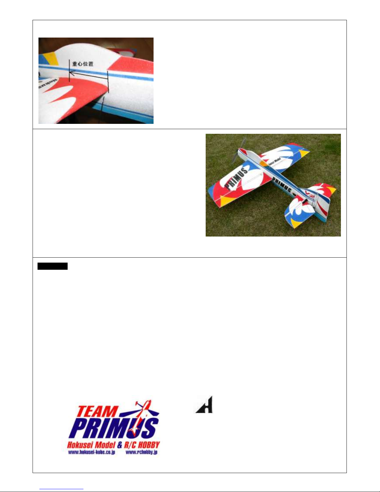
9. The Position of Center of Gravity
The Center of Gravity (CG) should be measured when everything (including the battery
pack) is put on the plane.
The suggested position of the CG for the plane is 100-110 mm behind the point where
the leading edge of the main wing meets the fuselage.
The suggested position of the CG is only meant to provide as a starting point to explore
the “best”position of the CG. The “best”position is different for different pilots and
different flying styles.
Please adjust the position of the CG by moving the position of your battery forward or
backward to find the most desirable position of the CG for your plane.
You may use batteries of different types, sizes, and weights. Find the right position for
your particular battery to get the optimum CG by experimenting.
Now your Primus EPP is ready to fly!
This plane is made of EPP (expanded polypropylene) material with carbon
fiber reinforcement. As a result, it is much more durable than balsa planes.
Minor crashes will normally not cause any damage to the airframe; and more
serious ones mostly create cracks, which are often easily repairable with glue
such as 3M Scotch 6225n glue in the flying field, in the airframe. Therefore,
this plane can be a wonderful trainer for practicing new maneuvers.
This plane is designed for slow acrobatic flying. Please do not stress the
airframe with high-speed acrobatic maneuvers.
Handling lithium polymer (LiPo) batteries
Electric acrobatic model planes are becoming more and more popular with the
advancement of LiPo battery technology. However, LiPo batteries can be a fire
hazard if they are handled properly.
Please read the instruction from your LiPo battery vendor or manufacturer carefully, and only use LiPo battery chargers to charge LiPo batteries.
Never overcharge or over-discharge your LiPo batteries.
Warnings:
This plane is designed for advanced hobbyist. Beginners please seek help from those who are experienced in acrobatic model airplanes.
This plane is designed for slow acrobatic flying using a 350-400 class brushless motor powered by an 11.1v LiPo battery pack. Please do not
overpower your plane with a much larger motor powered by a higher-voltage battery pack.
This plane is designed to have just enough strength required by slow acrobatic flying so as to keep the total weight down for high
performance. If you want to use the plane for high-speed acrobatic flying, please reinforce it with carbon fiber materials and glass fiber
tapes.
EPP material can change its shape under stress, especially in high temperature. Therefore, care must be applied in transporting and storing
your EPP planes to avoid their distorting. Do not, for example, leave your EPP planes in a vehicle for a long time on a hot summer day. The
best way to store an EPP plane is probably hanging it vertically with the nose up.
Be a responsible RC pilot. Check the power system, batteries, radio control equipment, all of the control surfaces, and the flying field before
flying. Always fly safely.
The product is an ARF kit, which needs further cutting to make all the components fit together.
Although this plane is much more durable than a typical balsa plane, it is not indestructible in a crash. The building material and parts can be
ruined if they are handled with excessive force or incorrectly. Care is still needed during either building or flying the plane
Flying the plane with wide-open throttle in level or dive flight may cause its wing to twist or flutter, which may lead to disintegration of the
plane in the air. Similarly, violent maneuvers such as blenders and snap-rolls may also lead to disintegration of the plane in the air. Please
manage the throttle and flying speed wisely. Hokusei will not be held liable for such disintegration.
Read the manual for your ESC carefully before using it for the first time. It is a good idea not to install a prop onto your motor when trying a
new power configuration for you motor start spinning unexpectedly.
Read instruction for your LiPo batteries carefully and handle them with caution.
Contact Info:
International Division, Hokusei Model
916 Shenye Mansion, 1027 Wenjin Zhong Road Luohu District,
Shenzhen, China 518001
Tel: (86)755-82253767 Fax: (86)755-82203767
Authorized International Dealer:
http://www.BestValueRC.com
- 7 -
Table of contents
Popular Toy manuals by other brands

Model Shipways
Model Shipways Charles W.Morgan instruction manual

Fisher-Price
Fisher-Price Sparkling Symphony Trumpet instructions

Freewing
Freewing FJ307 user manual

Parrot
Parrot Disco FPV user guide

Hasbro
Hasbro Marvel RISING SECRET WARRIORS E2699 instructions

VQ Model
VQ Model GRUNAU BABY instruction manual