manuals.online logo
Brands
  1. Home
  2. •
  3. Brands
  4. •
  5. HOKUYO AUTOMATIC
  6. •
  7. Repeater
  8. •
  9. HOKUYO AUTOMATIC EWF-0EA-N User manual

HOKUYO AUTOMATIC EWF-0EA-N User manual

HOKUYO AUTOMATIC CO., LTD.
Approved by
Checked by
Drawn by
Designed by
T i t l e
Drawing
No.
Symbol
Amended reason
Pages
Date
Corrector
Amended No.
Optical Data Transmission Device for
Ethernet EWF-0EA/B-N Specification
C-42-04433
1/9
×1
4
30th Aug. 2019
FA-8271
Supported network
Tamaki
19th July. 2019
OPTICAL DATA TRANSMISSION
DEVICE
For Ethernet
EWF-0EA/B-N
(Master/Normal/Slave mode)
SPECIFICATION
Oka
Oka
T i t l e
Drawing
No.
Optical Data Transmission Device for Ethernet
EWF-0EA/B-N Specification
C-42-04433
2/9
1. General
This device is a repeater that can connect to the Ethernet line directly. No need of MAC address or IP setting
and it can be used as a LAN cable. It can use Ethernet line between network cameras and host/slave for the
communication. Communication distance up to 50m, converts to optical wireless communication and
possible to communicate between moving devices. Be sure to use A type and B type as a pair.
2. Structure
Red light
EWF-0EA-N
LAN
LAN
DC24V
DC24V
EWF-0EB-N
Communication
connector
Internal power
(DC/DC)
Power supply
connector
Transformer
PHY
CPU
Waveform
circuit
Laser drive
circuit
Receiver
amplifier
Mode
switch
Indicator
lamp
T i t l e
Drawing
No.
Optical Data Transmission Device for Ethernet
EWF-0EA/B-N Specification
C-42-04433
3/9
3. Specification
Model
EWF-0EA-N
EWF-0EB-N
Transmission distance
50m
Directional angle
Full angle 1.4°
Power supply
DC24V (±10%)
Current consumption
120mA(DC24V)
Transmission method
Full-duplex two-way transmission
Transmission speed
100Mbps
Laser safety
Class 1
Interface
Ethernet
Communication standard
IEEE802.3u 100BASE-TX With Auto-Negotiation function
Modulation method
Direct modulation
Connection
Mini clamp connector (Power/CD signal), Modular jack RJ-45 (Ethernet)
Ambient temperature/
humidity
-10°C to +50°C 85%RH or less (without dew, frost)
Ambient illuminance
10000lux or less (Halogen/mercury lamp)
Impact resistance
490m/s2X, Y and Z directions each 10 times
Vibration resistance
10 to 55Hz double amplitude of 1.5mm for 2 hours in each X, Y and Z direction
Protective structure
IP40
Reception output(CD)
Photo-coupler open collector (pressure resistant 36V),
ON during light reception (Max.50mA, residual voltage 1.5V)
Level voltage output
(Analog output)
Approx.0 to 3V, connector S2B-PH-K-S (JST)
Connection connector PHR - 2*
Use during optical axis adjustment only.
External wiring is not possible.
* Cables for connection are not included. Please inquiry separately if needed.
About the laser safety
EWF-0EA/B-N laser safety standard is class 1.
Wavelength 658 nm (red)
Standard IEC60825-1 2007 & 2014
Class 1 Laser Product
Do not look directly into the laser beam.
Caution
T i t l e
Drawing
No.
Optical Data Transmission Device for Ethernet
EWF-0EA/B-N Specification
C-42-04433
4/9
・Supported network
EtherCAT® is a patent technology and registered trademark licensed by Beckhoff Automation GmbH, Germany.
4. Connection
* Attached connector cable dimension is as follows. If using the other cable, prepare suitable connector for
the used cable.
Power supply pin assignment
Pin No.
Signal
I/O circuit
1
COM
2
CD
3
-VIN (0V)
Power supply input
4
+VIN (DC24V)
Connector pin assignment for level voltage output
Model No.
AWG No.
Nominal cross-section
Finished dimension
37104-2206-000FL
AWG 20 to 22
0.3 to 0.5mm²
1.6 to 2.0mm
RJ-45 communication connector
TM11R-5M2-88-LP (Hirose product)
Mode switch
(Refer to section 6.
operation mode)
Main body side power connector
37204-1BE0-004(3M)
Connection connector (attached)
37104-2206-000FL
Connector for level voltage output
S2B-PH-K-S (JST product)
(Use lid cover during normal operation)
Connection connector (not included)
PHR-2
FG Terminal (M3 screw)
36V
CD
COM
Photo-coupler output
T i t l e
Drawing
No.
Optical Data Transmission Device for Ethernet
EWF-0EA/B-N Specification
C-42-04433
5/9
Pin No.
Signal
1
LEVEL
2
GND
*Connection connector PHR-2 and connection cable are not included.
If necessary, please contact us separately.
LAN connector (8P): RJ-45 8pin modular jack
5. Indicator lamp
W
*This device contain a circuit which corrects the delay time during high speed stable communication.
Pin No.
MDI Signal
Signal Function
1
TD +
Transmission Data (+)
2
TD -
Transmission Data (-)
3
RD +
Reception Data (+)
4
-----
Not Used
5
-----
Not Used
6
RD -
Reception Data (-)
7
-----
Not Used
8
-----
Not Used
P S L2 L1 C R
Socket view
View from the matting side
8 1
Optical axis indicator lamp
Use to confirm from the opposite side facing device,
same as level indicator lamp L2
P: Power supply indicator lamp
S : Status lamp (*)
L2: Level indicator lamp (led up when level margin 2 times)
L1: Level indicator lamp (led up when level margin 1.5 times)
C: Carrier detection indicator lamp (CD) (led up when level
margin 1 time)
R: Optical link lamp (led up when optical link is established)
T i t l e
Drawing
No.
Optical Data Transmission Device for Ethernet
EWF-0EA/B-N Specification
C-42-04433
6/9
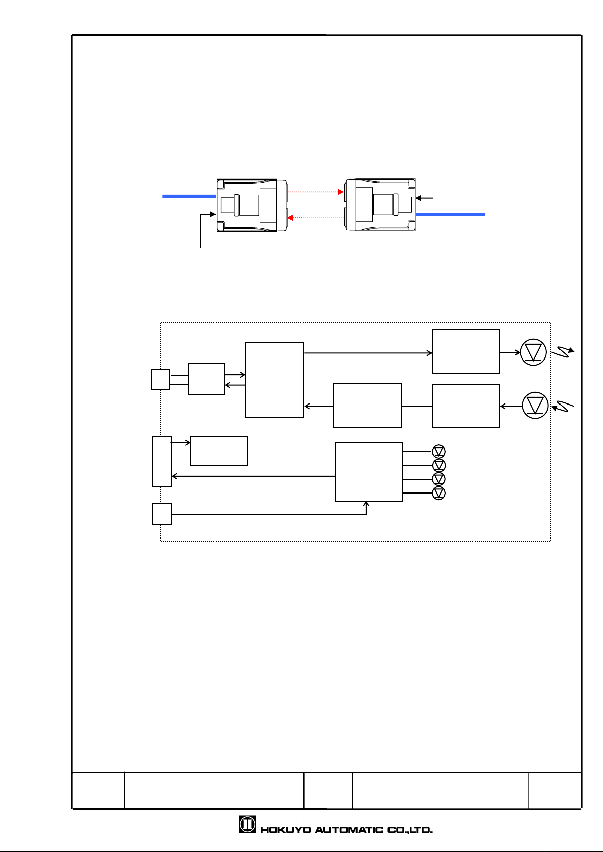
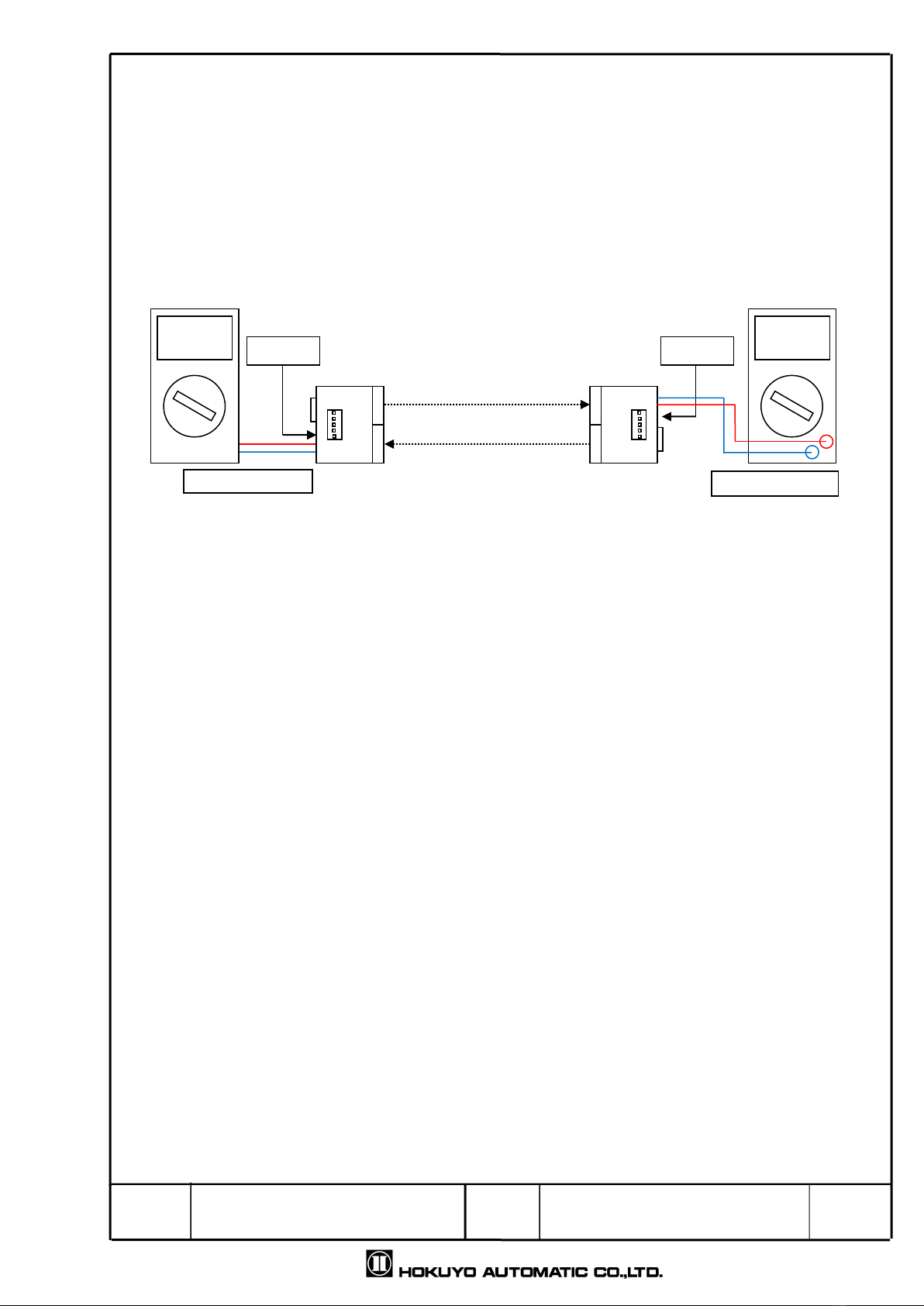
Status lamp (S) led up during normal circuit operation. Also, communication is possible when both status
lamp and CD lamp led up.
Also, in this device, the light emission power is constantly monitored inside the device. In the case, when
the light emission power is other than allowable level, the indicator lights C, L1 and L2 blinks. Stops the
emission and will be in error mode.
During error mode, check if the device returns to normal operation by restarting the power supply,
If error mode continues without recovery, please contact customer support.
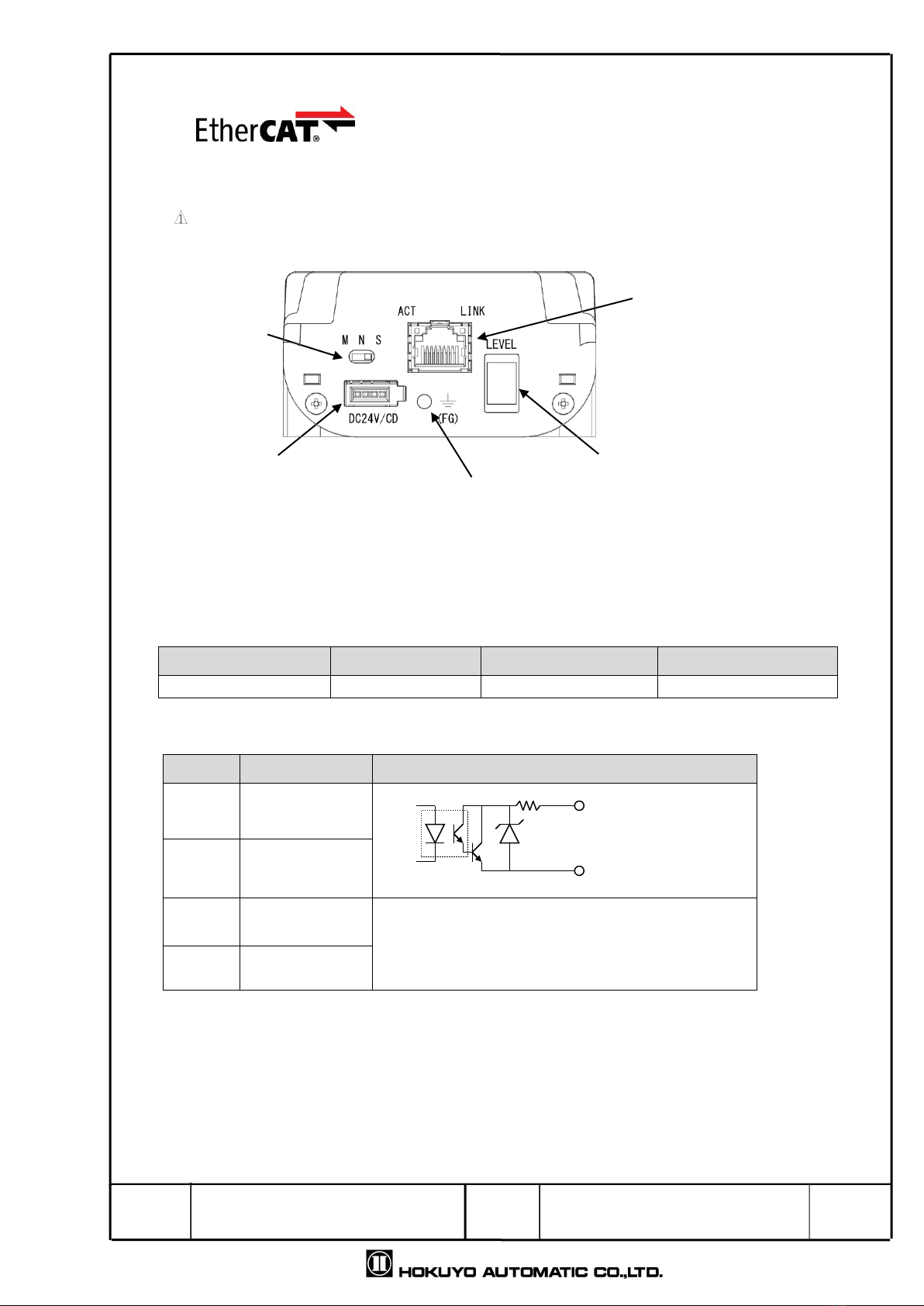
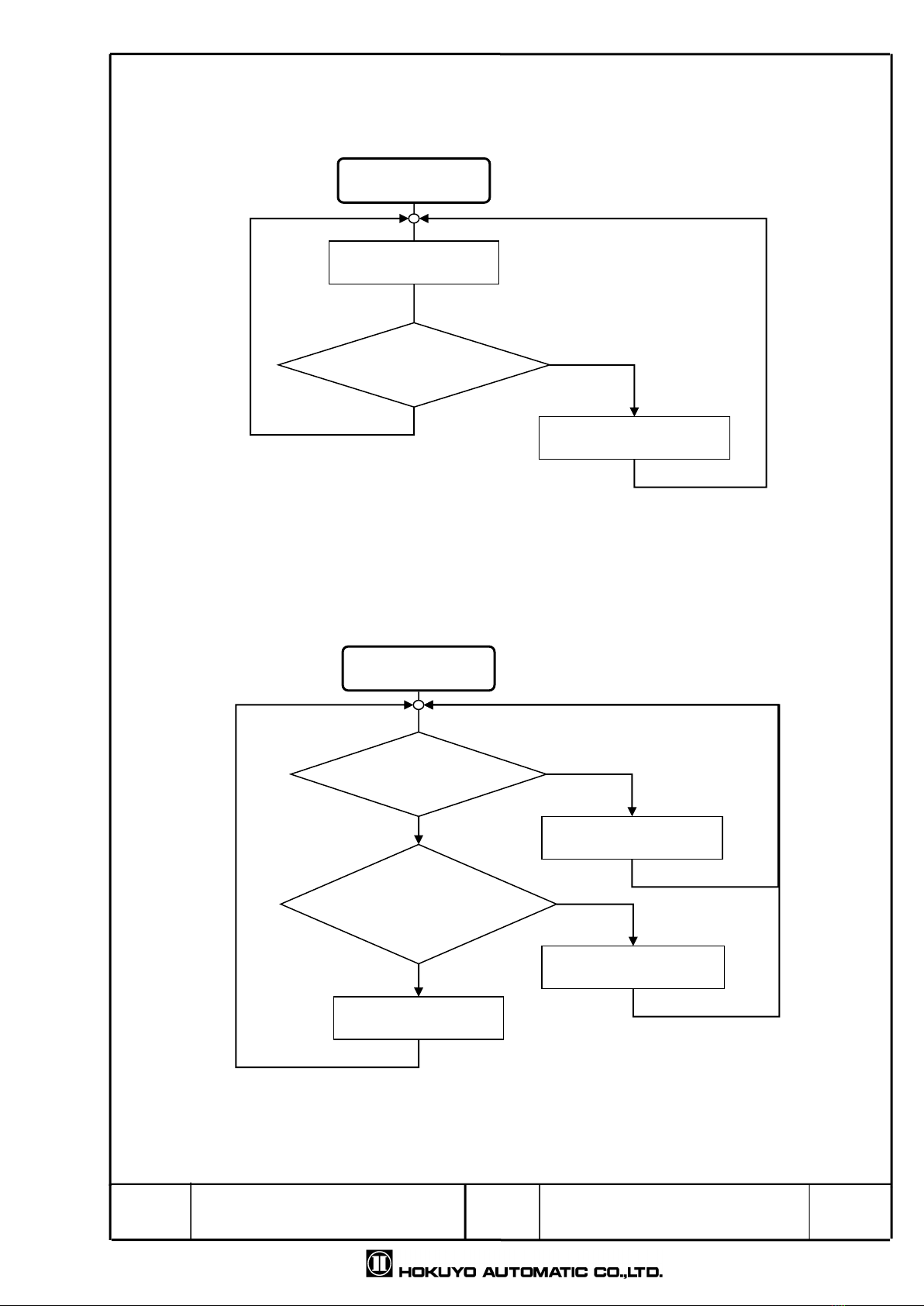
6. Operation mode
Slide switch which is located beside RJ connector, it can change to master mode, normal mode and slave
Red:LAN Active lamp
Green:LAN Link lamp
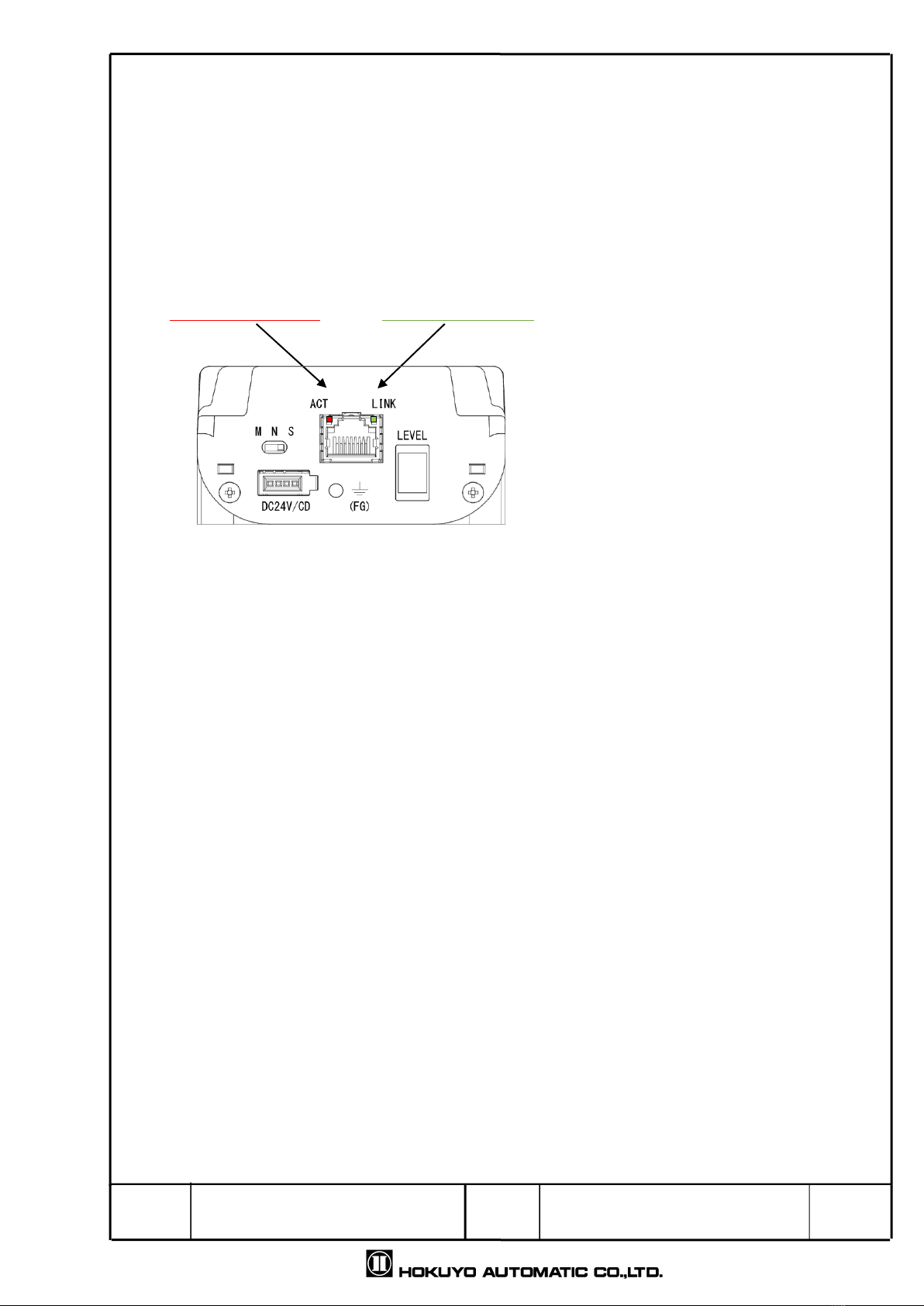
Active : Led up when transmitting/receiving data.
Link : Led up when link is established.
T i t l e
Drawing
No.
Optical Data Transmission Device for Ethernet
EWF-0EA/B-N Specification
C-42-04433
7/9
mode. During power supply, mode is set according to switch state.
Mode switching position
The possible data communication combinations are as follows
A Type or
B Type
B Type or
A Type
Communication
During light
interruption
LAN link
During light
interruption
emission state
Normal mode
Normal mode
Possible
Link connected
Emits on both side
Master mode
Master mode
Possible
Link disconnects
Emits on both side
Master mode
Slave mode
Possible
Link disconnects
Emission OFF of
Slave only
Slave mode
Slave mode
Not possible
Both link does not
connects
Does not emits on
both side
*Do not use other operation mode combination than above. It may be the reason of data communication
failure.
In normal mode only, even the communication is interrupted LAN side link will not be disconnected.
While using in the Ether CAT network, make sure EWF connecting to the master side should be in master
mode. EWF connecting to the slave should be in the slave mode.
During EWF optical adjustment, make sure to use as master mode or normal mode as a pair
(In sleep mode, if LAN link is not ON, laser does not emits.)
Each mode operation is as the following flow chart
Master
Slave①
Slave②
Red: Master mode
Blue: Slave mode
EWF
・・・
・・・
Master mode (M)
Slave mode (S)
Normal mode (N)
EWF
T i t l e
Drawing
No.
Optical Data Transmission Device for Ethernet
EWF-0EA/B-N Specification
C-42-04433
8/9
Master mode
Light projecting
Light receiving?
Disconnects LAN Link
YES
NO
Slave mode
Light receiving?
Disconnects LAN Link
YES
NO
Light projecting
Connected LAN link?
YES
NO
Stop emitting
Slave mode
・Emits when light receiving and LAN link is ON.
・When not receiving the light LAN link is
usually OFF.
Master mode
・Usually light projecting.
・When not receiving the light LAN link
is usually OFF.
T i t l e
Drawing
No.
Optical Data Transmission Device for Ethernet
EWF-0EA/B-N Specification
C-42-04433
9/9
7.Optical axis adjustment
Change EWF operation mode to normal mode or master mode of both A and B.
Make sure that each level output voltage of A and B can be checked with a tester.
Swing sidewise A to adjust so that the level output voltage of B becomes maximum
Swing sidewise B to adjust so that the level output voltage of A becomes maximum
*If a reflector is installed on the optical axis or near EWF, the level output voltage cannot be measured
properly due to the reflected light. Also, it may cause communication error. Please be careful while
installing the reflector.
DC24V
EWF-□EA
Master mode
Tester
3.00V
Level voltage output
EWF-□EB
Master mode
DC24V
Tester
3.00V
Level voltage output
Red light

This manual suits for next models

1

Popular Repeater manuals by other brands

Corinex High Performance Repeater I installation guide

Corinex

Corinex High Performance Repeater I installation guide

Blurex Wireless-N quick start guide

Blurex

Blurex Wireless-N quick start guide

AVR HR01-4K6G user manual

AVR

AVR HR01-4K6G user manual

Yaesu WIRES-X TM-400FT5D Adding proxy agent nodes

Yaesu

Yaesu WIRES-X TM-400FT5D Adding proxy agent nodes

Yaesu DR-1 Operation manual

Yaesu

Yaesu DR-1 Operation manual

COMBA mBDA-200 user manual

COMBA

COMBA mBDA-200 user manual

Orion MINI-REP V2 Installation, operation & maintenance manual

Orion

Orion MINI-REP V2 Installation, operation & maintenance manual

SpectraLink DECT Repeater installation guide

SpectraLink

SpectraLink DECT Repeater installation guide

DAVIS Wireless Repeater 7624 Instruction

DAVIS

DAVIS Wireless Repeater 7624 Instruction

General Sensors WIAR3 instruction manual

General Sensors

General Sensors WIAR3 instruction manual

Spectrum SCR1000 Operation and maintenance manual

Spectrum

Spectrum SCR1000 Operation and maintenance manual

Wurth Elektronik ANR001 manual

Wurth Elektronik

Wurth Elektronik ANR001 manual

Perle eR-S1110 quick start guide

Perle

Perle eR-S1110 quick start guide

logika WL-ZRPMNPW-G11-01 product manual

logika

logika WL-ZRPMNPW-G11-01 product manual

Tyco DSC WS8920 installation instructions

Tyco

Tyco DSC WS8920 installation instructions

Yaesu DR-1X operating manual

Yaesu

Yaesu DR-1X operating manual

HIK VISION DS-PR1-WE quick start guide

HIK VISION

HIK VISION DS-PR1-WE quick start guide

Black Box Twin Mux Repeater Module - UTP manual

Black Box

Black Box Twin Mux Repeater Module - UTP manual

manuals.online logo
manuals.online logoBrands
  • About & Mission
  • Contact us
  • Privacy Policy
  • Terms and Conditions

Copyright 2025 Manuals.Online. All Rights Reserved.