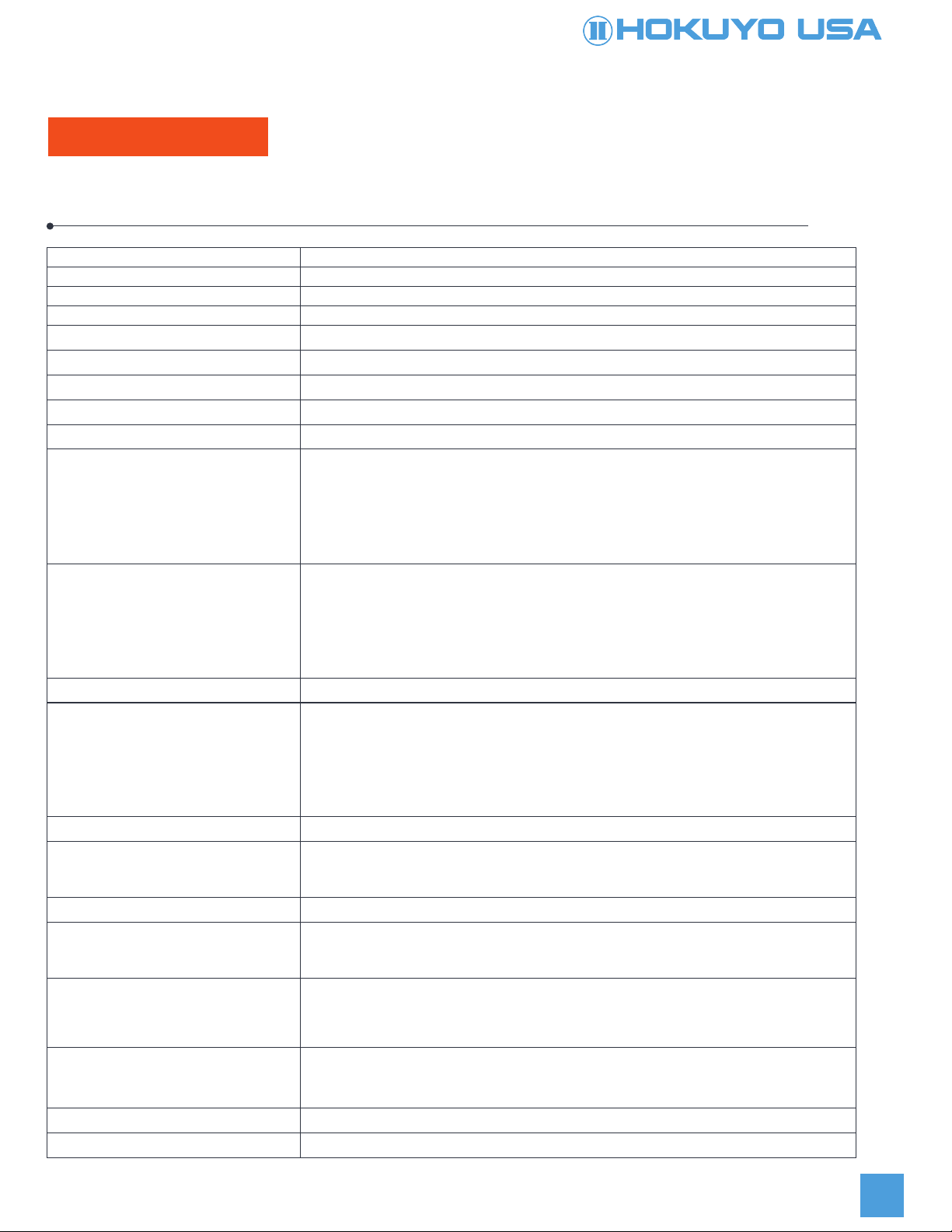
Hokuyo UGM-50LAP User manual

Scanning Laser Range Finder
UGM-50LAP
2D Lidar

The UGM-50LAP scans a semicircular field using a laser beam (λ= 905 nm), then calculates coordinates by measuring
the distance to an object and its corresponding step angle and detects obstacles within the setting area.
・This product can output distance data using the communication protocol SCIP.
・This product is Class 1 laser product.
・You can set scan speed / angular resolution from three modes.
・It is possible to reduce the influence of interference between multiple units of this product using the synchronized
rotation of the motor inside products. This function synchronizes the motor rotation to an external reference signal.
• You can configure "detached area setting" in areas away from the UGM-50LAP
・The UGM-50LAP has a function of the dirt detection (contamination detection) on the optical window. This product
can output a control signal when detecting dirt on the optical window.
2
1. General
Detection Area
UGM-50LAP
Field of view: 190°
Configuration (Laser Scanning Image)
In Normal Mode
Angular resolution: 0.32°
594 step
0 step
120m
297 step
Normal Mode 20ms / 3000rpm
Angular resolution/Scan speed
0.32°
Angular resolution
190°
Field of View
0 to 594 step
Step
297 step
Low speed mode 40ms / 1500rpm 0.16° 190° 0 to 1188 step 594 step
High resolution mode
80ms / 750rpm 0.08° 190° 0 to 2376 step 1188 step
Front step
The specifications in normal mode, low speed mode, and high resolution mode are as follows.
Measurement Area

・The UGM-50LAP (hereafter referred as sensor) is not certified for functional safety.
・This sensor cannot be used for human body detection as per the machinery directives.
・This sensor emits laser for measurement. Sensor’s operation may become unstable under the influence of strong
interference light or when emitted lights are not reflected back from object.
・The sensor’s operation may become unstable due to rain, snow and fog or due to dust pollution on the optical window.
・Rules and regulations related to safety should be followed strictly when machine users and system
designers operates the sensor.
・When there is a risk that the this sensor is used for weapons of mass destruction, weapons and equipment aimed at killing
human beings, and relevant technologies, etc., or when its usage for those purposes has become clear, sales may be
prohibited in accordance with the Foreign Exchange and Foreign Trade Act, and the Export Trade Control Order (Japanese
law). Moreover, regarding export of products, the formalities according to laws/Export Trade Control Order are
implemented in order to maintain international peace and safety.
・Use of controls or adjustments or performance of procedures other than those specified herein may result in hazardous
radiation exposure.
・Before using the sensor, please read carefully and understand this specification.
2. Disclaimer
3

3. Product Specs
Product Name 2D LiDAR
Model UGM-50LAP
Supply voltage DC 24V +/-10%
Supply current Steady state current: 1A or less, Starting Current: 1.5A or less, without Heater *1
Power Consumption 24W or less (Steady state and current)
Heater Voltage DC24V
Heater Current Steady state and Starting current : 2A or less, Only Heater*2
Heater Power Consumption 48W or less
Measurement resolution 1mm
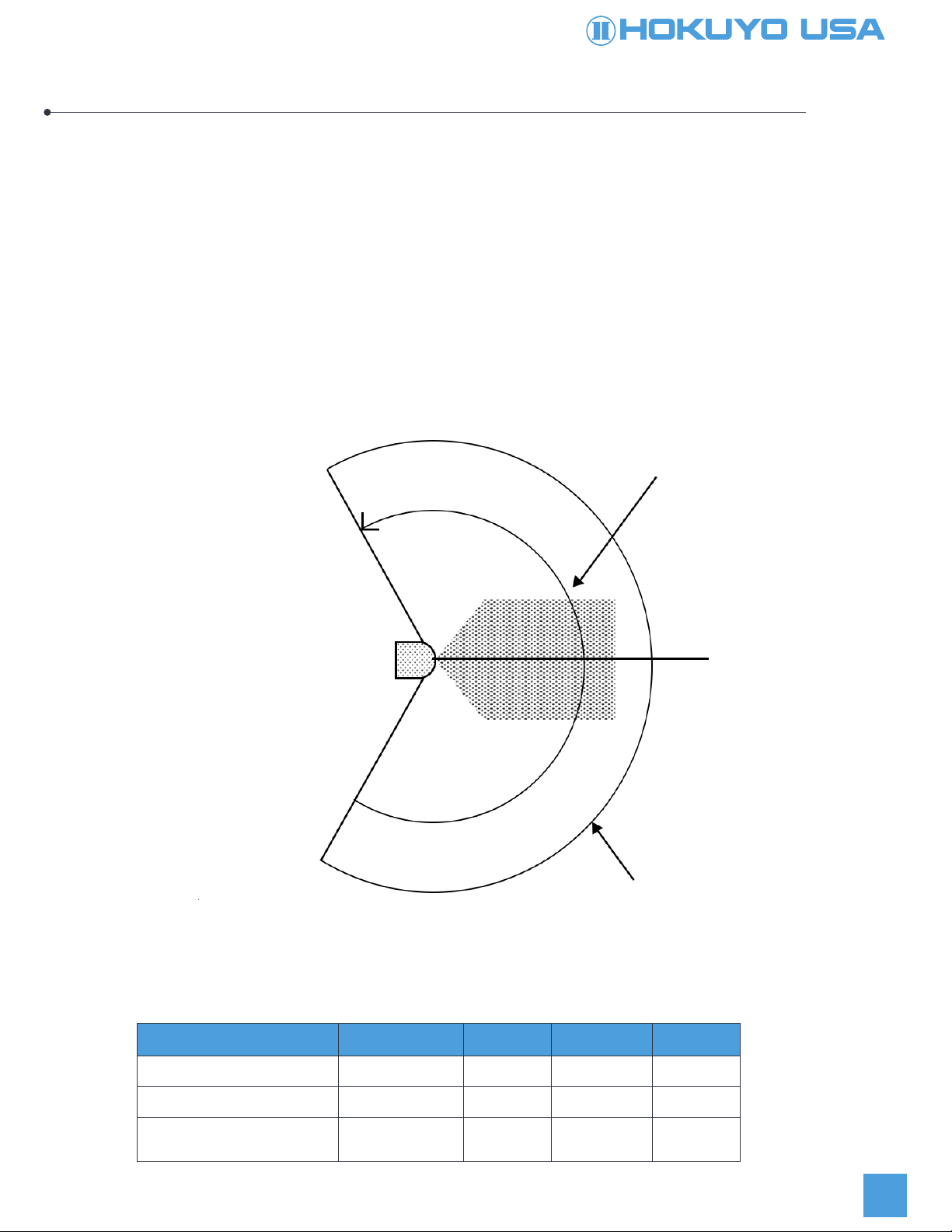
190*
Detection range and object Guarantee detection range:
0.1m to 50m*3 (10% Reflectance Black paper 500mm×500mm)
0.1m to 120m*4 (90% Reflectance white Kent paper1400mm×1400mm)
Maximum area setting : 120m (Distance output range 160m)
Minimum detectable size
Normal mode : 65mm (5m), 130mm (10m), 260mm (30m)
High resolution mode : 33mm (5m), 65mm (10m), 130mm (30m)
Average Accuracy by distance 10% Reflectance Black paper
0.1m to 30m:±30mm (Indoor 1,000lx or less)
30m to 50m:±40mmm (Indoor 1,000lx or less)
0.1m to 50m:±50mm*5 (Outdoor 100,000lx or less)
90% Reflectance white Kent paper
0.1m to 50m:±30mm
0.1m to 50m:±50mm*5 Ambient illuminance : 100,000lx or less
Repeat accuracy
Scanning angle
Within 30 sec after power supply
Start up time
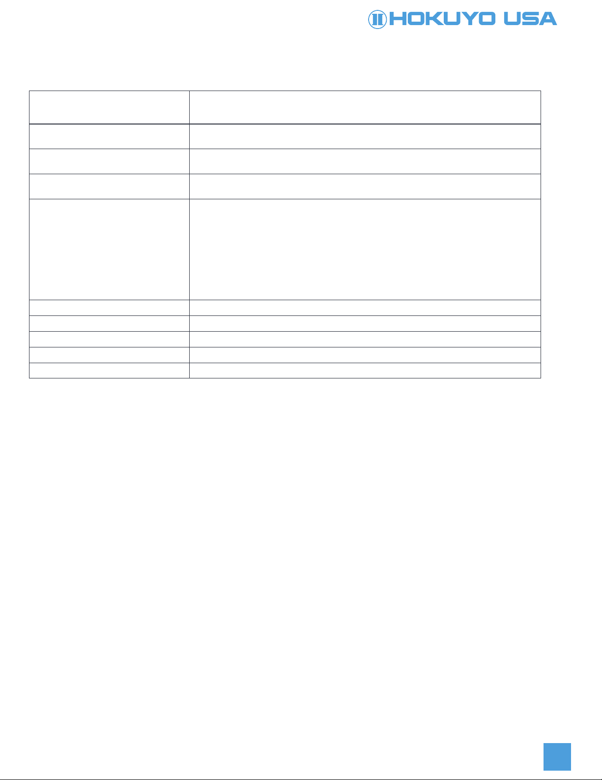
Ethernet 100BASE-TX(Auto-negotiation)
Interface
4 LEDs (Yellow green, Orange, Blue, Red)
LED display
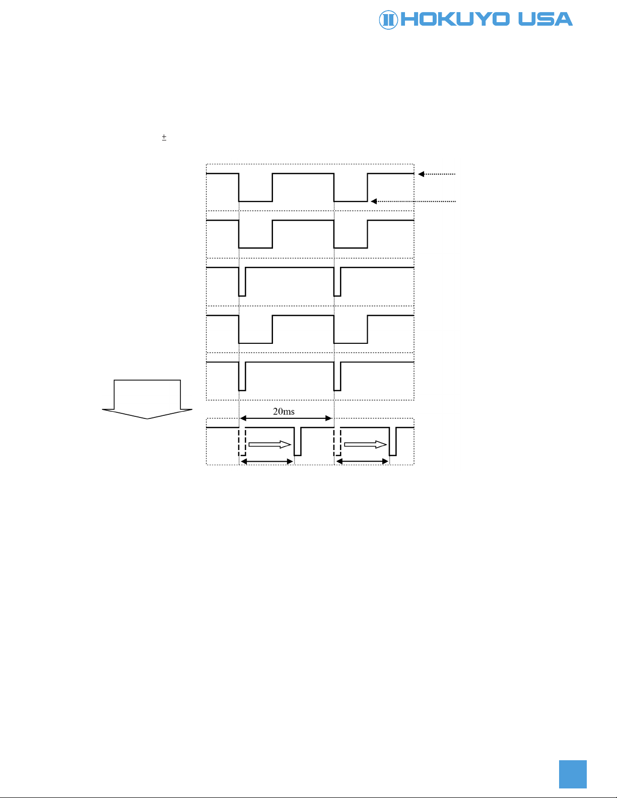
20ms*6(Normal mode 3000rpm)/ approx. 0.32°(360°/1125)
40ms*6(Low speed mode 1500rpm)/ approx.0.16°(360°/2250)
80ms*6(High resolution mode 750rpm)/ approx.0.08°(360°/4500)
Scan speed/ Angular resolution
7 PNP OUTPUTS : Synchronization master output, Synchronization output
Malfunction output, Contamination output, Area detection 1 to 3
(Open collector output DC30V 50mA MAX.)
Outputs
40msec or less (Normal mode)
80msec or less (Low speed mode)
160msec or less (High resolution mode)
In either case, change depending upon the delay setting
Output response time
7 INPUTS : Synchronous input, IP Reset input, Reboot input, Area input 1 to 4
(All 15 patterns)
(Photocoupler input, Cathode common, Input ON current 2mA)
Inputs
10% Reflectance Black paper
0.1m to 30m:σ<9mm (Indoor 1,000lx or less)
30m to 50m:σ<15mm (Indoor 1,000lx or less)
0.1m to 50m:σ<15mm*5 (Outdoor 100,000lx or less)
90% Reflectance white Kent paper
0.1m to 50m:σ<9mm (Indoor 1,000lx or less)
0.1m to 50m:σ<15mm*5 (Outdoor 100,000lx or less)
UGM-50LAP
4
Light source Laser semiconductor (905nm), FDA Laser Safety Class 1 (IEC60825-1:2014)

Protective structure IP67 IEC60529:2001
Insulation resistance 10MΩ
Weight Approx. 4.2kg (without connection cables)
Material Optical window : Polycarbonate, Body : Aluminum
Dimensions(W×D×H) 155mm × 166mm × 176mm (Without connector) External dimension:MC40-03391
*1 When a heater power is not connected or OFF.
*2 This is the current consumption of only heater. Details of heater operation is described in “8. Heater Function”.
*3 Indoor environment (under fluorescent lamps, 1,000 lx or less)
*4 In the high resolution mode(750rpm), the guarantee detection range is 120m.
*5 Detection cannot be guaranteed when direct light (such as sunlight) enters into the inside of the product.
*6 You must restart the sensor after changing the scan speed.
*7 Please check the influence of ambient environment on the detection accuracy using a product.
Ambient temperature and humidity -10 to +50°C below 85%RH
-30 to +50°C below 85%RH (While using the heater)
(Without dew, frost)
Environment eect A measured distance will be shorter than an actual distance under the influence of rain,
snow and direct sunlight.*7
Vibration resistance 10 to 150Hz 5G
IEC60068-2-6:2007
Shock resistance 3 times 50G, 1000 times 25G
IEC60068-2-27:2008
EMC standards (EMI)
EN61326-1:2013
EN55011:2009 + A1:2010
(EMS)
EN61326-1:2013
EN61000-4-2:2009
EN61000-4-3:2006 + A1:2008 + A2:2010
EN61000-4-4:2012
EN61000-4-6:2009
EN61000-4-8:2010
5
Notes:
Specifications (continued)

Sensor power supply +V(24V±10%)1
2
3
4
Function
Sensor power supply GND -V (0V)
Heater power supply (24V±10%)
Heater power supply GND(0V)
M12 4 core A-code socket (Female)
M12 4 core D-code plug (Male)
I/O1 : M12 8 core A-code socket (Female)
I/O2 : M12 12 core A-code socket (Female)
6
4. Connection
PIN No.
TX+1
Function
RX+2
TX-3
RX-4
PIN No.
Reboot1
Function
IP Reset2
Synchronization input3
Synchronization output4
PIN No.
IN
IN
IN
OUT
Synchronization master output
5
NC6
+COM7
-COM8
OUT
-
-
-
Contamination output1
NC2
Malfunction output3
Area output 14
OUT
-
OUT
OUT
Area output 2
5
Area output 36
Area input 17
Area input 28
OUT
OUT
IN
IN
Area input 3
9
Area input 410
+COM11
-COM12
IN
IN
-
-
I/O
FunctionPIN No. I/O
4.1 Power supply connector
4.2 Ethernet Connector
4.3 I/O Connector

Input: Photocoupler input (Cathode common, 5mA during each input ON, 0.5 mA or below during OFF)
Output:Open-collector output
Example of connecting the input/output circuit
Connect both +COM and –COM to I/O Power.
Maximum output current 50mA
30V
1V or less
24±10%V
Item
Maximum voltage
Output residual voltage
+COM Power supply range
Specification
7
I/O Power
Load
10K
10K
1K
4.7K
VCC
GND
VCC
GND
-COM
IN
OUT
+COM
Internal Circuit
4.4 Input/output circuit

5. Control signal
8
5.1 Malfunction Output
5.2 Synchronization output
(1) Laser malfunction : When laser emission is not possible or laser power has exceeded the safety class 1.
(2) Motor malfunction : When motor rotation inside the sensor is unstable. When a malfunction occurs, the UGM-50LAP
switches the malfunction output to OFF (Low level), and then stops laser emission and motor rotation. You can check the
error code using communication protocol SCIP. Refer to troubleshooting table in section 6 for error details.
The UGM-50LAP outputs a pulse of 1ms every one scan for synchronizing with the scanning. The timing of the
synchronization signal is shown in the figure below.
* Scan speed 20ms (In normal mode)
* Description based on scan speed 20 ms
5.3 Synchronization master output
This is a reference clock signal for synchronizing motor rotation of each sensor.
The UGM-50LAP outputs the clock signal with cycle of 20ms and the output-OFF period (Low level) of 5ms (Duty25%).
Synchronization master output is continued even in the malfunction state.
Scan Direction
Synchronization
Signal
Synchronization output is ON under malfunction.
Output=OFF
(High level)
Output=ON
(Low level)
Synchronization Output
is OFF duration
19ms1ms
Measurement Range
Synchronization Output
1ms

・When the synchronization master output of the master is not connected to the synchronization input of the slave, the
synchronization output terminals of both the master and the slave sensors continue to output pulse signals accordingly
with a cycle of 20ms and low of 1ms.
9
5.4 Synchronization input
5.6 Timing chart of synchronization input/output
In a multiple connection of UGM-50LAP, you can synchronize with motor rotation inside each sensor.
By connecting the synchronization input terminal of the slave to both synchronization master output terminal and the
synchronization input terminal of the master, you can synchronize the motor rotation of the slave with the motor rotation of
the master. Synchronization is performed on the falling edge of the clock signal.
As shown in the figure above, it is possible to synchronize the motor rotation of the slave with the motor rotation of the
master according to the shifted scanning time of each slave sensor by setting phases of each slave sensor.
You can confirm and configure phases using the application software.
5.5 Example of connection between multiple sensors for synchronization of motor rotation
UGM-50LAP
Slave
UGM-50LAP
Master I/O power supply
Input -COM
Input -COM
Synchronization input
Synchronization master output
Output+COM
0V
DC24V
Synchronization
input
ON: High Level
Synchronization
master output
(Master)
Synchronization
input (Master)
*No Input
Synchronization
output
(Master)
Synchronization
Input (Slave)
*No input
Synchronization
output
(Slave)
OFF: Low Level
ON: High Level

ON: High Level
OFF: Low Level
Synchronization
master output
(Master)
Synchronization
Input (Master)
Synchronization output
(Master)
Phase: 0°
Synchronization
Input (Slave)
Synchronization output
(Slave) Phase : 0°
Phase Dierence
180°
Phase Dierence
180°
Synchronization output
(Slave)
Phase :180°
10
When the synchronization master output of the master is connected to the synchronization input of the slave,
the master sensor can synchronize falling edges of the synchronization master output signal with falling edges of the
synchronization output signal.
When the phase value is set, the synchronization output with the phase is shifted by the set value only. Error of phase
setting should be within 1ms.
Change of phase
setting by application
5.7 IP Reset input
Return the IP address to the initial value (192.168.0.10).
Switch to ON (High level) for 2 seconds or more, then switch to OFF (Low level) for IP address initialization.
Notes:
Before you switch o the sensor power, you need to make sure that IP Reset input is in the Low level. If you switch o the
sensor while IP Reset input is in High level, the sensor may not start normally after that.
5.8 Reboot input
When switching to ON (High level) for 2 seconds or more, you can restart the sensor operation.
5.9 Contamination output
When detecting dirt on the optical window (contamination detection) : ON (High level)
When not detecting dirt on the optical window (No contamination detection) : OFF (Low level)

5.10 Area input and selection area set
The setting of three regions are available for one area. The three regions correspond to the detection output 1, output 2,
and output 3 respectively. You can select an area set number by switching the area input 1 to input 4. The setting of 15
patterns are available.
However, when inputs 1 to 4 are all on (High level), the sensor operates in the emission stop mode.
* ON:High level, OFF : Low level
* Input response time is up to 2 scans.
* In the emission stop mode, detection outputs (1 to 3) are switched to ON.
* If all areas (input 1 to 4) are open, area 15 is selected.
11
ON ON ON ON Stop emission
OFF ON ON
ON
ON Area 1
ON OFF ON Area 2
OFF OFF ON ON Area 3
ON ON OFF ON Area 4
OFF ON OFF ON Area 5
ON OFF OFF ON Area 6
OFF OFF OFF ON Area 7
ON ON ON OFF Area 8
OFF ON ON OFF Area 9
ON OFF ON OFF Area 10
OFF OFF ON OFF Area 11
ON ON OFF OFF Area 12
OFF ON OFF OFF Area 13
ON OFF OFF OFF Area 14
OFF OFF OFF OFF Area 15
Area input 1 Area Input 2 Area Input 3 Area Input 4 Area Set

5.11 Detection Output
When detecting within configured area, output is switched to OFF (Low level). When not detecting within configured area,
output is switched to ON (High level). In a malfunction state, each detection output is switched to OFF state.
12
AON ON OFF
BON OFF OFF
COFF OFF OFF
Position of objects Detection Output 1
Example of detection outputs for object A, B and C are as shown below
UGM-50LAP
Detection Output 2 Detection Output 3

You can obtain the causes of errors from STAT line of the “II” command response in the communication protocol SCIP.
The error codes and solutions from the STAT line are as follows in table.
* Output signals will be undefined immediately after power-ON. The undefined time
depends on a motor speed(scan speed).
6. Troubleshooting
6.1 Error code table
6.2 Relation between product states and LED displays
6.3 Relation between product states and output signals
no error.000
Message
internal setup failed.051
internal chip access failed
052
100
ID
Product
states
Yellow green
(Power)
LED
Normal operation
Sensor processing system error
Same as above
encoder error.
motor startup failed. Motor error
Unstable motor rotation
Laser error
Same as above
Same as above
250
motor rotation error.251
laser too high.300
Encoder error
Meaning
No action is required.
Sensor has failed and
needs to be repaired.
Reduce the vibration and noise to the sensor
Reduce the ambient light and
noise to the sensor
During start up ON OFF
ON when heater is
activated.
Blinks
(2sec. intervals)
201
200
laser too low.301
laser no echo.302
During operation ON OFF
ON when heater is
activated.
ON when an object
is detected.
During Malfunction ON OFF
OFF OFF
During Motor stop
(sleep) ON OFF
ON when heater is
activated.
Blinks
(4sec. intervals)
During contamination
detection Same as operation
IP initialization ON ON when heater is
activated.
Blinks
(1sec. intervals)
Blinks
(1sec. intervals)
Solution
13
Red
(Malfunction)
Blue
(Detection)
Orange
(Heater)
Synchronization
master output
Product States
During start up Tr=ON(High) Tr=ON(High)
During operation
Continuous output
after power supply
is ON.
1 ms per cycle
Tr=OFF(Low) Tr=ON(High)
During Malfunction Tr=ON(High) Tr=OFF(Low)
During Motor stop
(sleep) Tr=ON(High)
Same as operation
Tr=ON(High)
Tr=ON(High)
Tr=OFF(Low)
Tr=ON(High)
Tr=OFF(Low)
Tr=OFF(Low)
Tr=OFF(Low)
Tr=ON(High)
Tr=OFF(Low)
During contamination
detection
IP initialization Tr=ON(High)
Malfunction
output
Contamination
detection
Synchronization
output

TheUGM-50LAPhasaheaterinsidetheproducttopreventdewcondensationontheopticalwindow.Youcanselect
either“Active”or“Inactive”usingtheapplicationsoftware.TheinitialoperationmodeoftheheaterfunctionisInactive.
Whentheheaterfunctionisactivated,theheaterwilloperateifthetemperatureinsidetheproductdecreasesbelow
0°C.Whenthetemperatureinsidetheproductincreasesmorethan10°C,theheaterwillstopitsoperation
automatically.
7. Heater function
Thisfunctionisenabled“Active”usingtheapplicationsoftware.Whenthisfunctionisenabled“Active”,contamination
outputwillswitchtoON(High)iftheopticalwindowiscontaminatedabovecertainlevel.TheUGM-50LAPwill
continuetooperateandtherewillbenomalfunctionstop.
8. Optical window contamination warning function
Thisfunctionisenabled“Active”usingtheapplicationsoftware.Whenthisfunctionisenabled“Active”,contamination
outputwillswitchtoON(High)iftheopticalwindowiscontaminatedabovecertainlevel.TheUGM-50LAPwill
continuetooperateandtherewillbenomalfunctionstop.
IPdefaultvalue:192.168.0.10
Portnumber:10940
9. Ethernet setting
9.1 Default value
YoucanchangeIPaddressusingadedicatedapplicationsoftware.
9.2 About changing IP address
SwitchIPresetinputtoON(High)for2secondsormore,thenswitchtoOFF(Low).
9.3 IP address initialization

Table of contents