XL-FW1114-01 1
FW3510
FW3510/FW3410 &
FW3110
FIFTH WHEEL
OPERATING MANUAL
WARNING
You must read and understand
the instructions in this
manual before operating
your fifth wheel.
Failure to follow all of the
important operating procedures
contained in these instructions
may result in a hazardous
condition or cause a hazardous
condition to develop.
These instructions apply to the
proper operation of your fifth
wheel only. There are other
important checks, inspections,
and procedures not listed here
that arenecessary,prudent,
and/or required by law.
Table of Contents
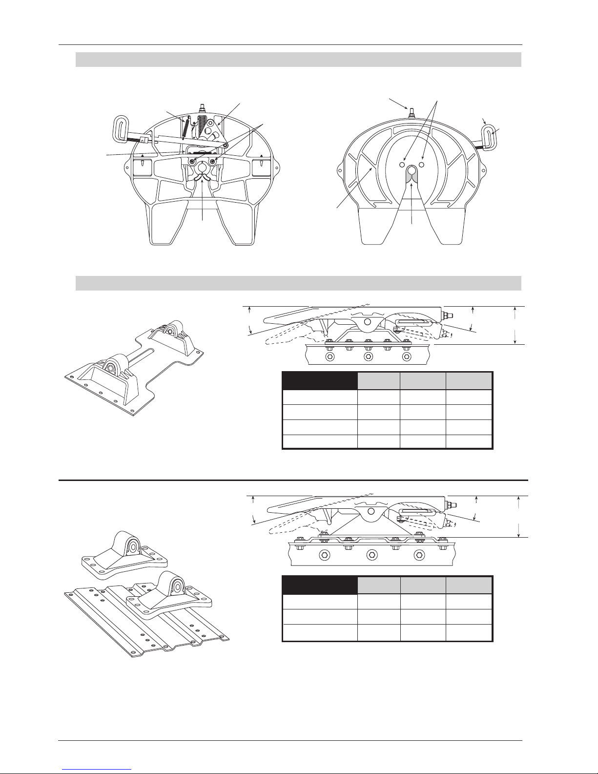
1. Component Part Identification and Specifications
1.1 Identification of component parts . . . . . . . . . . . . . . . . . . . . . . . . . . . . . . . . . . .2
1.2 Important specifications . . . . . . . . . . . . . . . . . . . . . . . . . . . . . . . . . . . . . . . . . . .2
2. Operating Instructions
2.1 Pre-service inspection . . . . . . . . . . . . . . . . . . . . . . . . . . . . . . . . . . . . . . . . . . . . .3
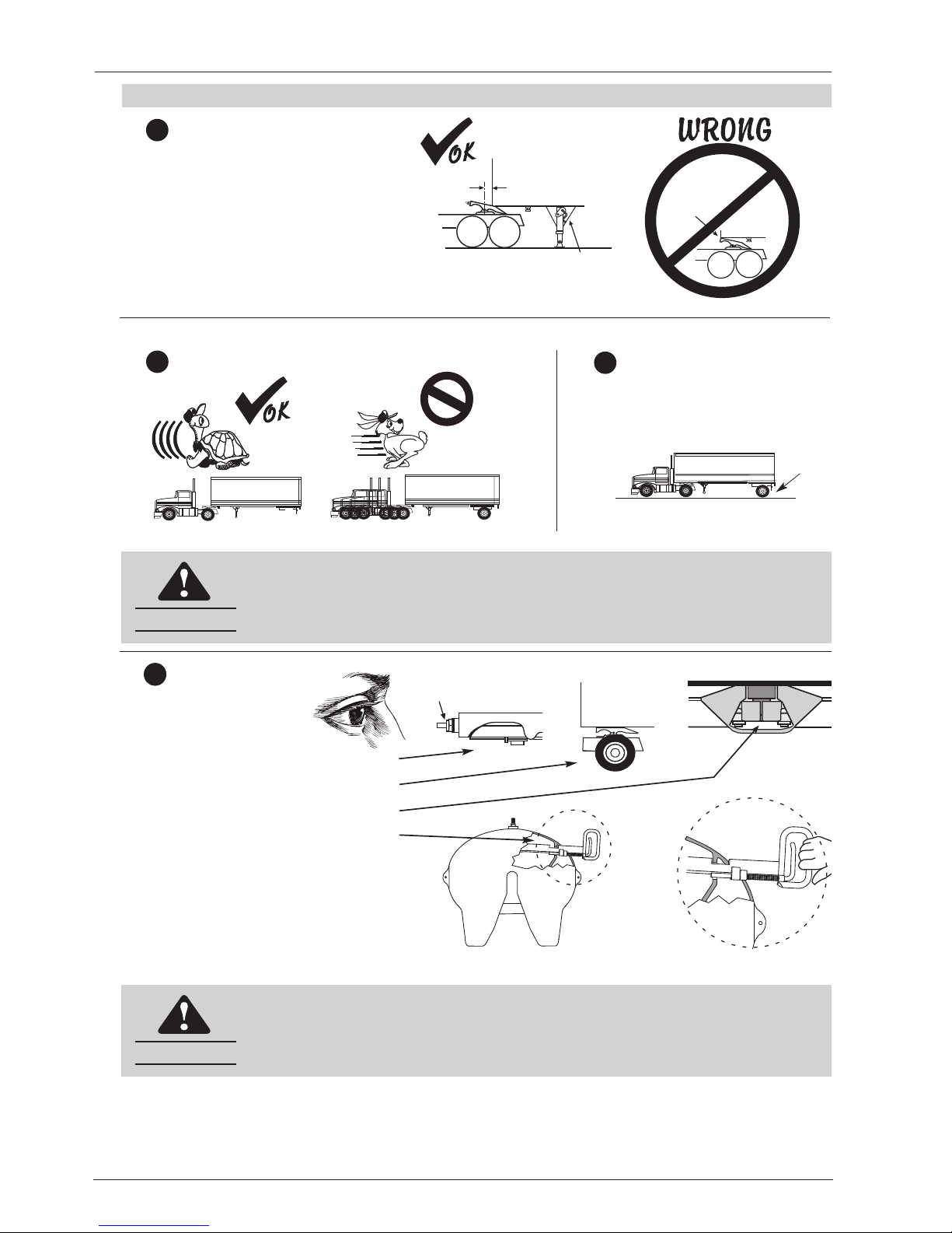
2.2 Trailer coupling procedures . . . . . . . . . . . . . . . . . . . . . . . . . . . . . . . . . . . . . . . . .3-4
2.3 Trailer uncoupling procedures . . . . . . . . . . . . . . . . . . . . . . . . . . . . . . . . . . . . . .5
3. Routine Inspection and Maintenance
3.1 As Needed Lubrication . . . . . . . . . . . . . . . . . . . . . . . . . . . . . . . . . . . . . . . . . . . .6
3.2 Required Inspections and Adjustments . . . . . . . . . . . . . . . . . . . . . . . . . . . . . . . .6-8
3.2.1 General fifth wheel inspection . . . . . . . . . . . . . . . . . . . . . . . . . . . . . . . . .6
3.2.2 Inspection of locking mechanism . . . . . . . . . . . . . . . . . . . . . . . . . . . . . . .7
3.2.3 Lock adjustment procedure . . . . . . . . . . . . . . . . . . . . . . . . . . . . . . . . . . . .7
 User manual")

 User manual")