BENDIX Sheppard Mounting instructions

1
The Sheppard®Active Steering System by Bendix CVS
SD-25-50062
Figure 1 – The Sheppard®Active Steering System by Bendix CVS Uses a Windshield-Mounted Camera
Vehicle Equipped with the
Sheppard®Active Steering System by Bendix CVS
Compatible Windshield-
Mounted Camera NOT TO SCALE
DESCRIPTION
The Sheppard®Active Steering System by Bendix
CVS is a driver assistance system, helping the driver
with a suite of steering assist features and driver
assist steering features integrated with the Bendix®
FLC-20™ camera, Bendix®Wingman®Fusion™or a
compatible third party camera. The active steering system
does not replace the driver or driving skills.
The driver is solely responsible for maintaining control
of the vehicle with both hands on the steering wheel.
The active steering system combines unique active
steering technology with a forward-facing camera for active
lane correction. This system helps mitigate potential side
collisions and lane-departure related accidents, as well as
increase driver comfort.
Bendix safety technologies complement safe driving
practices. No commercial vehicle safety technology
replaces a skilled, alert driver exercising safe driving
techniques and proactive, comprehensive driver
training. Responsibility for the safe operation of the
vehicle remains with the driver at all times.
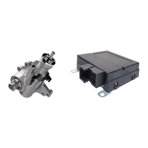
Figure 2 – System Components
Active Steering
Electronic Control
Unit (ECU)
• For installation of the Bendix®AutoVue®FLC-20™
camera see Bendix Service Data sheet SD-64-20124,
available on Bendix.com.
• For installation of the steering gear see the Sheppard®
D-Series Integral Power Steering Gear manual,
available on RHSheppard.com.
• For installation of the ECU see the OEM service
information.
Additional Reference Information
Magnetic Torque Overlay
Steering Gear
Bendix®AutoVue®
FLC-20™Camera
Trackable Lane Lines

2
Due to the inherent limitations of image recognition
technology, camera-based safety technology — on
rare occasions — may not be able to detect or may
misinterpret lane markings. At these times, alerts
may not occur, or erroneous alerts may occur.
Bendix safety technologies complement safe driving
practices. No commercial vehicle safety technology
replaces a skilled, alert driver exercising safe driving
techniques and proactive, comprehensive driver
training. Responsibility for the safe operation of the
vehicle remains with the driver at all times.
IMPORTANT: It is the responsibility of the driver to remain
vigilant and change driving practices depending on trac
and road conditions.
Improper use of the Sheppard®Active Steering
Assist System by Bendix CVS can result in a collision
resulting in property damage, serious injuries, or
death. Be sure to read, understand, and carefully
follow the instructions this document.
This product may expose you to chemicals
including Nickel, which is known to the State of
California to cause cancer and birth defects or other
reproductive harm. For more information, go to
P65Warnings.ca.gov.

3
DRIVER ASSISTANCE FEATURES
LANE KEEP ASSIST (LKA)
• Detects lane markings and evaluates relative vehicle
position
• Recognizes when the vehicle begins to drift towards
the lane markings
• Distinguishes between planned lane changes and
lane drifting
• Intervenes before the vehicle reaches the lane markings
• Automatically applies a correction torque to the steering
wheel
• Smoothly releases steering torque as soon as the
vehicle trajectory is re-established
• The system enables the driver to suppress or override
steering torque
• LKA is activated at 37 mph / 60 kph
STEERING ASSIST
• Speed Dependent Steering Assist - Provides variable
steering assist based on vehicle speed. It helps the
driver experience easier steering at low speeds and
a rmer steering response at higher speeds. It also
aids the driver by reducing fatigue and helps the driver
maintain better control of the vehicle.
• Active Return - Helps to reduce driver fatigue through
easier maneuvering by returning the steering wheel to
the center position at lower vehicle speeds.
• Crown/Side-Wind Compensation - Helps to reduce
driver fatigue, or steering eort, by helping keep the
vehicle straight during heavy side winds, crowned
roads, or some alignment issues.
• Road Disturbance Compensation - Helps improve
driver comfort by reducing steering wheel vibration
typically caused by road disturbances like potholes,
road debris, or other bumps in the road.
SYSTEM COMPONENTS
BENDIX®AUTOVUE®FLC-20™CAMERA
• The forward-facing camera tracks the lane markers and
provides the lane characteristics for the left and right
marker to the Sheppard®Active Steering System by
Bendix CVS system over the vehicle communication
network. In addition, the system also provides
information on when the lane departure warnings
will be suppressed, allowing the LKA feature to be
suppressed at the same time. See Figure 3.
• For additional information, see the Bendix®AutoVue®
FLC-20™ Camera Service Data sheet SD-64-20124
available for download on bendix.com.
• Is compatible with later versions of Bendix®Wingman®
Fusion™systems.
LDW WINDSHIELD MOUNTING BRACKET
• The bracket that holds the camera secure and keeps
it facing the correct direction to successfully determine
lane width and position. See Figure 3.
Figure 3 – Bendix®
AutoVue® FLC-20™Camera & Bracket
Bendix®AutoVue®
FLC-20™Camera
Camera
Bracket
ACTIVE STEERING ECU
• The Electronic Control Unit (ECU) for the Sheppard
Active Steering System by Bendix CVS is a standalone
unit designed to work with J1939 Vehicle CAN and a
forward-facing lane sensing camera. See Figure 4.
Figure 4 – Lane Keep Assist Electronic Control Unit (ECU)
ECU
Connector
4
MAGNETIC TORQUE OVERLAY POWER
STEERING GEAR
• Perform a visual inspection to ensure proper installation
and functionality. The power steering gear with magnetic
torque overlay should be clean and free of uid. All
connectors around the gear should be connected and
secured. See Figure 1.
• For additional service and troubleshooting information
see the Sheppard®D-Series Integral Power Steering
Gear manual available online from the Customer
Service tab on RHSheppard.com.
TROUBLESHOOTING
SAFETY GUIDELINES
Read and follow the General Safety Guidelines shown
on Page 2 of this document.
IMPORTANT
All vehicle Diagnostic Trouble Codes (DTCs)
related to the engine, transmission, instrument
cluster, engine cruise control, and Bendix®ABS,
ATC, or ESP® systems must rst be resolved, with
no DTCs present during the vehicle operation
while in cruise control, prior to running Bendix®
ACom®Pro diagnostics to resolve Sheppard®
Active Steering System by Bendix CVS DTCs
faults.
IMPORTANT
System Problems. If a problem with the Sheppard®
Active Steering System by Bendix CVS is detected, it
should be serviced as soon as possible to restore full
functionality. The vehicle does not need to be taken
out of service, the Lane Keep Assist (LKA) will be
deactivated.
STARTING BENDIX®ACOM®PRO
DIAGNOSTIC SOFTWARE
The Bendix®ACom®PRO Diagnostics Software can
be started from the desktop shortcut, or from the main
Windows®screen with “Start…Programs…Bendix…ACom
PRO Diagnostics Software”. To begin, the technician
selects “Connect” from the upper panel. See Figure 5.
Figure 5 – Starting Bendix® ACom®PRO Diagnostic
Software
NOTE: When using ACom PRO Diagnostic Software for
the rst time, the service technician will need to check the
communication adapter for the Sheppard Active Steering
System by Bendix CVS controller. The technician will
need to indicate which communication protocol to use with
“Application Settings…Preferences…Connection”. Once
a successful connection has been made, these steps will
no longer be necessary. See Figure 6.
The Bendix ACom PRO Diagnostic Software for Active
Steering System User Guide is available in the software
download and should be used as a reference to all functions
of the ACom PRO service tool.

5
Figure 6 – Bendix®ACom®Diagnostic Software –
Hardware Interface Screen
READING DIAGNOSTIC
TROUBLE CODES (DTCs)
If the system generates a Diagnostics Trouble Code (DTC),
where a lamp or icon is illuminated on the instrument
cluster, use a current version of Bendix®ACom®PRO
Diagnostic Software to troubleshoot. Select “Sheppard®
Active Steering by Bendix CVS” from the list on the left
panel. Read the DTCs from the list on the top-right panel.
See Figure 7.
DIAGNOSTIC TROUBLE CODES (DTCs)
Use a J1939 detection software to nd the DTC code(s).
Then go to Table 1 on page 6 to identify the appropriate
service action code needed to remedy the issue.
Figure 7 – Vehicle Selection Screen
Sheppard
®
Active Steering System by Bendix CVS

6
Table 1 – Diagnostic Trouble Codes
DIAGNOSTIC TROUBLE CODES (DTCs) AND CORRECTIVE ACTION
SPN FMI
DTC
Failure Condition Reset Condition Corrective ActionName Description
516700 0 System Thermal Error-
Temperature High
High
Temperature
of ECU
Temp >=115 C for 5 seconds Temp<=95C for 5 seconds
Perform ignition cycle.
516701
3Device Power- Voltage
Above Threshold Over Voltage VBATT>32 VBATT<=32
4Device Power- Voltage
Below Threshold Under Voltage VBATT<9 VBATT>=9
516702
5
Steering Assist
Hydraulic Pressure-
Open Circuit
Open Circuit Volt<0.5 for L and R
Ignition Reset
Diagnose either
pressure sensor,
wiring, or connection.
(Refer to connector
pinout page 11.)
3
Steering Assist
Hydraulic Pressure-
Short Circuit
Short Circuit Volt<4.5 for L and R
517554
2 Coil Implausible Data
Out of Range
Current
Command
Coil Current<-5 amps or
Coil Current >5 amps Ignition Reset
Check coil connection.
Potential coil and/or
Electronic Control Unit
(ECU) replacement
or software update.
10 Coil Current Stuck
Out of Range
Current
Command
Actual ≠ Measured
coil current within 5
percent tolerance
Ignition Reset
Potential coil/
wiring update or
software update.
516222
3ECU H Bridge
Short to Battery Short to Battery
When no drivers are ON:
Voltage on coil A > 5V
or
Voltage on coil B > 5V
or
When LS1 is ON: Current on
coil A in positive direction
(A-Coil-I-Plus)> 0A
or
When LS2 is ON: Current on
coil A in negative direction (
Ignition Reset Replace the ECU.
4 ECU H Bridge
Short to Ground
Short to
Ground
When no drivers are ON:
Voltage on coil A < 5V
or
Voltage on coil B < 5V
or
When HS1 is ON: Current
on coil A in positive
direction (A-Coil-I-Plus)>
0A
or
When HS2 is ON:
Current on coil A in
negative direction
(A-Coil-I-Minus)> 0A
Ignition Reset Replace the ECU.

7
DIAGNOSTIC TROUBLE CODES (DTCs) AND CORRECTIVE ACTION - CONTINUED
SPN FMI
DTC
Failure Condition Reset Condition Corrective ActionName Description
516222
2 ECU H Bridge NOK NOK
When LS1 is ON: Voltage
on coil A = 5V then LS 1
is NOK
or
When LS2 is ON: Voltage
on coil B = 5V then LS2
is NOK
or
When HS1 is ON: voltage
on coil A = 5V then HS1
is NOK
or
When HS2 is ON:
voltage on coil B = 5V
then HS2 is NOK
Ignition Reset
Replace the Electronic
Control Unit (ECU).
5 ECU H Bridge Openload Openload
When the measured
voltage at A and B = 0
when Low Side 1 Driver
is OFF
or
When the measured
voltage at A and B
= 0 when Low Side
2 Driver is OFF
Ignition Reset
516705 3 Warning Lamp Failure Failure LSS1-WL1-IN = 0 (Pin 4) LSS1-WL1-IN = 1
516706 19 Network Configuration
Mismatch SW Fault
Wakeup not configured
correctly (Mismatch in
Wakeup input) (CAN
wake up but ignition
line is connected)
Wakeup input
configured correctly
(Remove ignition line in
case of CAN wake up)
Using Bendix®ACom®
PRO perform the
End of Line (EOL)
configuration to
match the wiring.
516707
13
System Configuration-
Calibration Data set
Not Programmed
SW Fault
EOL Calibration not
performed. (Pressure
sensor trimming flag
! = 1 or coil polarity
check flag ! = 1)
EOL Calibration
performed (pressure
sensor trimming flag
= 1 or coil polarity
check flag = 1)
Using ACom PRO
perform the EOL
calibration.
12 System Configuration-
Bad Device SW Fault Flash Memory Error Ignition Reset Reflash to remove
memory failure
19 System Configuration-
Software Version SW Fault Version Mismatch
on DM13 No Version Mismatch
Match the software
version - Reflash the
correct software.
520193 5 Vehicle CAN BUS OFF CAN Fault BUS Open/ Short BUS Connected
Verify J1939 data
is on the vehicle
communications bus.
520194 5 Proprietary CAN
BUS OFF CAN Fault BUS Open/ Short BUS Connected
Check if the CAN bus
speed of the radar
and camera's private
CAN are identical
70 9 CAN_TO_CCVS1 CAN Time Out
Timeout > 300 ms and No
CAN_NO_BUS_
CONNECT Detected
CCVS_1 Transmitting Check the sending
ECU for proper
function and
active faults.
1121 9 CAN_TO_EBC1 CAN Time Out
Timeout > 300 ms and No
CAN_NO_BUS_
CONNECT Detected
EBC1 tranmitting
Table 1 – Diagnostic Trouble Codes - Continued

8
DIAGNOSTIC TROUBLE CODES (DTCs) AND CORRECTIVE ACTION - CONTINUED
SPN FMI
DTC
Failure Condition Reset Condition Corrective ActionName Description
904 9 CAN_TO_EBC2 CAN Time Out
Timeout > 300ms and
No
CAN_NO_BUS_
CONNECT Detected
EBC2 transmitting
Check the sending
Electronic Control
Unit (ECU) for
proper function
and active faults.
190 9 CAN_TO_EEC1 CAN Time Out
Timeout > 300ms and
no CAN_NO_BUS_
CONNECT Detected
EEC1 transmitting
1702 9 CAN_TO_FLI2 CAN Time Out
Timeout > 300ms and
No
CAN_NO_BUS_
CONNECT Detected
FLI2 transmitting
1814 9 CAN_TO_VDC1 CAN Time Out
Timeout > 300ms and
No
CAN_NO_BUS_
CONNECT Detected
VDC1 transmitting
1807 9 CAN_TO_VDC2 CAN Time Out
Timeout > 300ms and
No
CAN_NO_BUS_
CONNECT Detected
VDC2 transmitting
5676 9 CAN_TO_AEBS CAN Time Out
Timeout > 300ms and
No
CAN_NO_BUS_
CONNECT Detected
AEBS transmitting
5876 9 CAN_TO_OEL CAN Time Out
Timeout > 300ms and
No
CAN_NO_BUS_
CONNECT Detected
OEL transmitting
9751 9 CAN_TO_FLIC CAN Time Out
Timeout > 300ms and
No
CAN_NO_BUS_
CONNECT Detected
FLIC transmitting
70 19 CAN_OR_CCVS1_
PRK_BRK_SWT
CAN Out of
Range Signal
1 < signal < 0 0 <= signal <= 1
563 19 CAN_OR_EBC1_
ABS_CRTL_ACT 1 < signal < 0 0 <= signal <= 1
562 19 CAN_OR_EBC1_
ASRBrk_CRTL_ACT
CAN Out of
Range Signal 1 < signal < 0 0 <= signal <= 1
561 19 CAN_OR_EBC1_
ASREng_CRTL_ACT
CAN Out of
Range Signal 1 < signal < 0 0 <= signal <= 1
1121 19 CAN_OR_EBC1_
EBS_BRK_SWT
CAN Out of
Range Signal 1 < signal < 0 0 <= signal <= 1
521 19 CAN_OR_EBC1_EBS_
BRK_PDL_POSN_PER
CAN Out of
Range signal 100 < signal < 0 0 <= signal <= 100
904 19 CAN_OR_EBC2_
FA_SPD
CAN Out of
Range signal 64254 < signal < 0 0 <= signal <= 64254
190 19 CAN_OR_EEC1_
ENG_SPD
CAN Out of
Range signal 64255 < signa l< 0 0 <= signal <= 64255
2876 19 CAN_OR_OEL_
TRN_SIG_SWT
CAN Out of
Range signal 2 <signal < 0 0 <= signal <= 2
Table 1 – Diagnostic Trouble Codes - Continued

9
DIAGNOSTIC TROUBLE CODES (DTCs) AND CORRECTIVE ACTION - CONTINUED
SPN FMI
DTC
Failure Condition Reset Condition Corrective ActionName Description
1711 19 CAN_OR_FLI2_FWD_
LANE_TRK_R
CAN Out of
Range signal 1 < signal < 0 0 <= signal <= 1
Check the sending
Electronic Control
Unit (ECU) for
proper function
and active faults.
1710 19 CAN_OR_FLI2_
FWD_LANE_TRK_L
CAN Out of
Range signal 1 < signal < 0 0 <= signal <= 1
7474 19 CAN_OR_FLI2_
DRV_ALRT_LVL
CAN Out of
Range signal 100 < signal < 0 0 <= signal <= 100
7475 19 CAN_OR_FLI2_DRV_
ALRT_WAR_STATE
CAN Out of
Range signal 3 < signal < 0 0 <= signal >= 3
1816 19 CAN_OR_VDC1_ROP_
ENG_CON_ACTIVE
CAN Out of
Range signal 1 < signal < 0 0 <= signal >= 1
1818 19 CAN_OR_VDC1_ROP_
BRK_CON_ACTIVE
CAN Out of
Range signal 1 < signal < 0 0 <= signal >= 1
1817 19 CAN_OR_VDC1_YC_
ENG_CON_ACTIVE
CAN Out of
Range signal 1 <s ignal < 0 0 <= signal >= 1
1819 19 CAN_OR_VDC1_YC_
BRK_CON_ACTIVE
CAN Out of
Range signal 1 < signal < 0 0 <= signa l>= 1
5624 19 CAN_OR_VDC1_
TRLR_VDC_ACTIVE
CAN Out of
Range signal 1 < signal < 0 0 <= signal >= 1
5676 19 CAN_OR_AEBS_FOR_
COL_AEBS_STATE
CAN Out of
Range signal 7 < signal < 0 0 <= signal <= 7
1808 19 CAN_OR_VDC2_
YAW_RATE
CAN Out of
Range signal 3.92 < signal < -3.92 3.92 <= signal <= 3.92
Check the parameter
set of the sensor.
Check the sending
ECU for proper
function and
active faults.
1809 19 CAN_OR_VDC2_
LAT_ACC
CAN Out of
Range signal 15.687 < signal <- 15.687 15.687 <= signal
<= 15.687
Check the sending
ECU for proper
function and
active faults.
1807 19 CAN_OR_VDC2_
STR_WHL_ANG
CAN Out of
Range signal 31.374 < signal < -31.374 31.374 <= signal
<= 31.374
9751 19 CAN_OR_FLIC_LN_
KP_ASST_EN
CAN Out of
Range signal 1 < signal < 0 0 <= signal >= 1
9760 19
CAN_OR_FLIC_
ReqActSteering
DriverPrf_Md
CAN Out of
Range signal 1 < signal < 0 0 <= signal >= 1
520195 9 CAN_NO_BUS_
CONNECT
Open Fault
CAN
No (non UDS) messages
present on vehicle CAN
for 250 ms at all (not
limited to messages
explicitly received by unit)
At least one non-
diagnostic message
received
Verify J1939 data
is on the vehicle
communications
bus bar.
520196 2 Lane_Direction_
Qualifier
Mismatch
in camera
Left Right Lane
Information SAFE = Invalid
Left Right Lane
Information
SAFE = Valid
Verify that the
voltage at the
camera connector is
greater than 9 VDC.
520197 19 CAN_OR_VP131_X_
LCS_HazardDetected
CAN Out of
Range Signal
Signal < 0 OR sinal
= 2 OR signal = 3
0 <= signal <= 1
OR
signal = 4
Check the sending
ECU for proper
function and
active faults.
Table 1 – Diagnostic Trouble Codes - Continued

10
Pin 1-18: 1241374-2 Pin 19-25: 1-968851-1
Figure 9 – Terminals for Connector X2
CONNECTOR PIN IDENTIFICATION
Pins X2.1 through X2.18
Pins X2.19 through X2.25
Unsealed (Carrier) Housings for AMP
MCP 1.5 Receptacle Inserts
Pins Color Key TYCO Number
25 Black A 1-1718484-1
AMP MCP 1.5 Receptacle Insert
18 Black - 1718489-1
AMP MCP 2.8 Receptacle Insert
7 Natural - 1718488-1
Figure 8 – Connector X2

11
Pin Pin Name Function Pin Size
(Area)
X2.1 PRESSURE_SENS_1 Pressure signal (left sensor)
.5 mm2
X2.2 PRESSURE_SENS_2 Pressure signal (right sensor)
X2.3 PRESSURE_SENS_GND Pressure sensor GND
X2.4 PRESSURE_SENS_SUPPLY Pressure sensor supply
X2.5
X2.6
X2.7
X2.8
X2.9
X2.10 VEH-CANL Vehicle CAN Low
X2.11 VEH-CANH Vehicle CAN High
X2.12 SYS-CANL System CAN Low
X2.13 SYS-CANH System CAN High
X2.14
X2.15
X2.16 COIL_CURRENT_A Output current (5A)
X2.17 COIL_CURRENT_B Output current (5A)
X2.18
X2.19 WL1 Warning Lamp
2.5 mm2
X2.20 TRM-15 Ignition / Terminal 15
X2.21 SWITCH1 Input Switch for LKAS
X2.22 TRM-30A Ubat / Terminal 30A
X2.23
X2.24 SWITCH1_GND Input Switch GND
X2.25 TRM-31A GND / Terminal 31A
CONNECTOR PIN IDENTIFICATION
Table 2 – Connector Pin

12
PRESSURE SENSOR, COVER,
AND GASKET REPLACEMENT
If a pressure sensor has been identified as faulty or
damaged, it must be replaced. (A service kit is available
from R.H. Sheppard.) Once the faulty or damaged
pressure sensor is removed, follow the steps below for the
installation of the new sensor.
1. Align the gasket and pressure sensor with the half circle
cut-out in each part. See Figure 10.
2. Align the pressure sensor and gasket on the bearing
cap. See Figure 10.
3. Hand start and torque the front right, and back left
pressure sensor bolts to 13-16 ft-lb (17.6-21.7 Nm) with
the 5 mm hex (Allen®) bit. See Figure 10.
Figure 10 – Pressure Sensor and Gasket Figure 11 – Bolt Installation
Gasket
Pressure
Sensor
Pressure
Sensor Bolts
Cut-Out
Pressure
Sensor Bolts
Magnetic Torque
Overlay Steering
Gear
4. Remove the alignment xture (if used) and install the
pressure sensor cover by aligning the bottom tabs with
the open bolt holes. See Figure 11.
5. Hand start and torque the front left and back right bolts
to 13-16 ft-lb (17.6-21.7 Nm) through the tabs of the
pressure sensor cover with the 5 mm hex (Allen) bit.
See Figure 11.
MAGNETIC TORQUE OVERLAY
STEERING GEAR AND ECU
REPLACEMENT
To replace the steering gear or the ECU, please contact
the Bendix®Tech Team or Sheppard®Technical Support.
See page 13.

13
ADDITIONAL SUPPORT
Additional support at bendix.com / 1-800-AIR-BRAKE (1-800-247-2725), option 2
For the latest information, and for downloads of the Bendix®ACom®PRO Diagnostics software, and its User Guide, visit
the Bendix website at: bendix.com.
For direct telephone technical support, the Bendix Tech Team is available at 1-800-AIR-BRAKE (1-800-247-2725),
option 2. Follow the instructions in the recorded message. Representatives are available to assist you Monday - Thursday,
8 a.m. - 6 p.m. ET and Friday, 8 a.m. - 5 p.m. ET.
R.H. Sheppard Technical Support 1-800-274-7437
The Sheppard hours are: Representatives are available Monday – Friday, 7 a.m. to 6 p.m. ET.

14
10
17
18
11
7 8
16
19
14
13
12
15
2
4
3
1
5
6
9
Twisted Pair
120 Ohm
Twisted Pair
Tin, Twist, and Solder
Over Exposed Wire
Detail A
Heat Shrink
Heat Shrink
Heat Shrink
Heat Shrink
Heat Shrink
Heat Shrink
Twisted Pair
Orange TXL 14 AWG 3M
Red TXL 14 AWG 3M
Black TXL 14 AWG 3M
Yellow TXL 18 AWG 3M
Green TXL 18 AWG 3M
Gray GXL 20 AWG 3M
Blue GXL 20 AWG 3M
Violet GXL 20 AWG 3M
Green GXL 20 AWG 3M
Red GXL 18 AWG 3M
Green GXL 20 AWG 3M
Yellow TXL 20 AWG 3M
Black GXL 18 AWG 3M
Heat Shrink
Heat Shrink
Detail A
Heat ShrinkHeat Shrink
MS3102
R16S-1P
MS3106E1
6S-1S
Figure 13 – System Schematic

15
System Schematic Key (See page ??)
1Pins Color Key Tyco P/N
25 Black - 1718484-1
2
AMP MCP 1.5K, Contact
TE Internal Number:1241374-1
TE Internal Number:1355036
3
AMP MCP 1.5K Receptacle Insert
Pins Color Key Tyco P/N
18 Black - 1718489-1
4
AMP MCP 2.8Receptacle Insert
Pins Color Key Tyco P/N
7 Natural - 1718488-1
5Pins Only
TE P/N: 1534097-1 TE P/N: 1534101-1
6TE P/N: 5-963715-5
7Nylon Sheath from E.G. Manufacturer
8Heat Shrink E.G. from 3M
9120 Ohm 5% Resistor, Tinned, and Twisted with Line and
Soldered, Shrink Tube Covered - Qty 1
10 Recommend 5A Fuse
11 Free Ended Leads, User Suit to Application
12 TE Pins P/N: 2-964298-1
13 Delphi Connector P/N: 15498443
14 Molex®Pins P/N: 330122003
15 Molex Connector P/N: 31404-6213
16 Twisted Pair CAN (Lines should have no fewer than 1 turn
per 25 mm)
17 All Tolerances +/- 5 mm (unless otherwise specified)
18 All Crimp Terminals to be Fastened Per the Connector
Manufacturer Specifications (unless otherwise specified)
19 TE P/N: MS3102R16S-1P, TE P/N: MS3106E16S-1S,
TE P/N: 97-79-513-8 (boot on both male and female sides)
SYSTEM SCHEMATIC KEY

16
SD-25-21025 Rev. 000 © 2020 Bendix Commercial Vehicle Systems LLC, a member of Knorr-Bremse • 10/20 • All Rights Reserved.
Log-on and Learn from the Best
On-line training that's available when you are 24/7/365.
Visit brake-school.com.
Printed on recy
cled paper
This manual suits for next models
1
Table of contents
Other BENDIX Automobile Accessories manuals

BENDIX
BENDIX BlindSpotter BW2860 Configuration guide

BENDIX
BENDIX VORAD VS-400 Installation and operation manual

BENDIX
BENDIX Bendix Wingman Advanced User manual

BENDIX
BENDIX VORAD VS-400 User manual

BENDIX
BENDIX TABS-6 TRAILER ABS MODULE Mounting instructions

BENDIX
BENDIX SmarTire User manual

BENDIX
BENDIX Gen. 4 ABS ECU User manual

BENDIX
BENDIX ADB22X-V Mounting instructions

BENDIX
BENDIX Bendix Wingman ACB Mounting instructions

BENDIX
BENDIX Intellipark User manual