IM-142-A
marked on one of the remaining wires and make the connection.
Carefully, place connections in wiring chamber for future access.
See Figure 1.
2.2.4 Replace wireway cover. Tighten screws.
2.2.5 Access the lamp compartment by disengaging the latch
and lifting the top of the unit up. Disengage latch by rotating flat
side toward center of luminaire. Open slowly until the weight is
supported by the door stop. Install the proper lamp type. Tighten
the lamp carefully but securely. See Figure 1.
OPTICS ORIENTATION NOTES
Some of the fixtures in this series are equipped with optical
components that produce distributions of light that are not
symmetric and are intended to be aimed by orienting the prismatic
refractor a specific direction. The “Street Side” marking on the
refractor should be pointed toward the street. The marking is on
the top edge of the refractor.
2.2.6 Close top cover and engage latch.
2.2.7 Energize the luminaire. Check for proper operation.
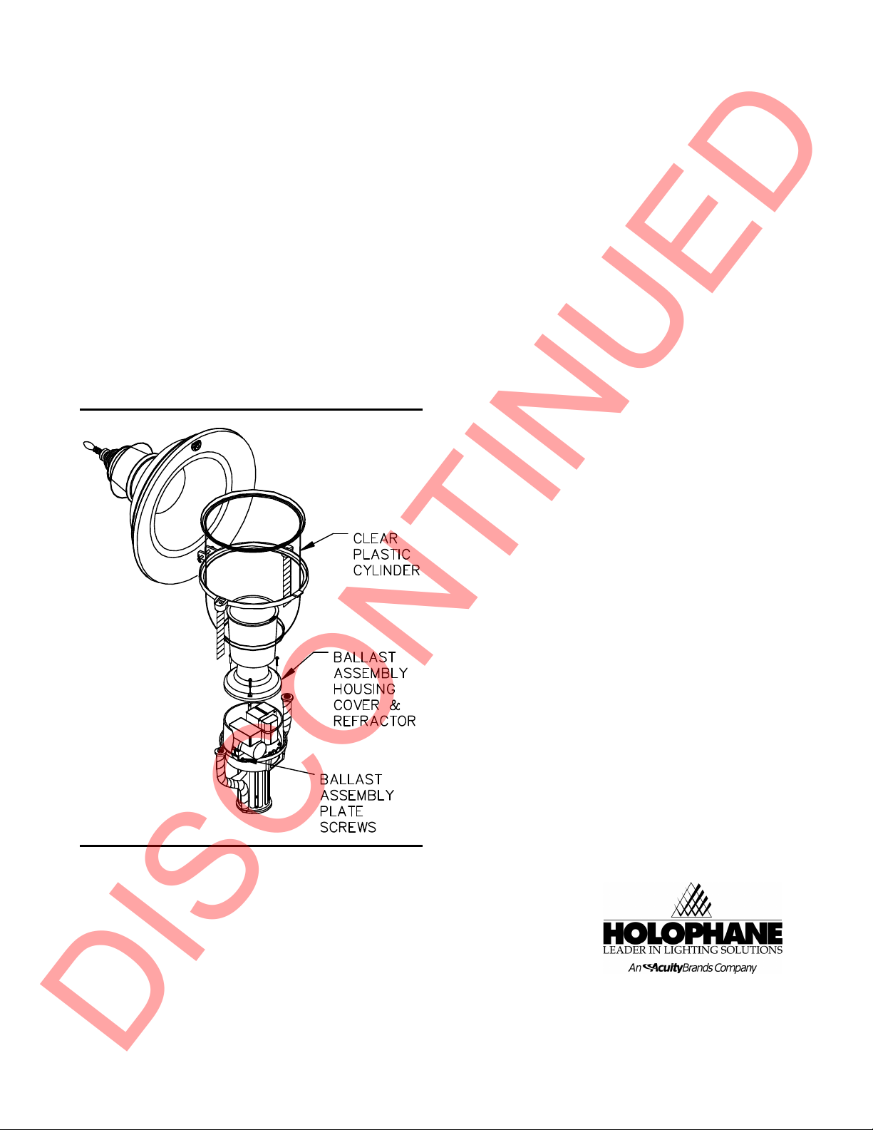
Figure 2
GR901
3. MAINTENANCE
3.1 Re-lamping and Cleaning
3.1.1 Wipe off exterior dirt and debris using a soft, clean cloth.
CAUTION
DO NOT USE ABRASIVE CLEANSERS ON OPTICAL
SURFACES. THEIR USE MAY RESULT IN THE LOSS OF
OPTICAL EFFICIENCY.
3.1.2 Disengage latch, by rotating flat side toward center of
luminaire, and open top cover. Refer to Figure 1.
3.1.3 Remove lamp and dispose of in a safe and proper manner.
3.1.4 Remove clear plastic cylinder by lifting straight up. Refer to
Figure 2.
3.1.5 Wipe plastic cylinder with damp soft cloth (do not use
chemical agents on plastic).
3.1.6 Wipe the refractor interior with a clean dry cloth.
3.1.7 Install the proper lamp type. Tighten the lamp carefully but
securely.
3.1.8 Close top cover and engage latch.
3.1.9 Energize the luminaire. Check for proper operation.
3.2 Electrical Component Replacement
3.2.1 Remove two screws to wireway cover and remove wireway
cover.
3.2.2 Disengage latch by rotating flat side toward center of
luminaire and open top cover. See Figure 1.
3.2.3 Remove the lamp.
3.2.4 Remove refractor and ballast assembly housing cover by
removing the three screws in cover. Note the orientation of the
glass for reinstallation.
3.2.5 Lift ballast assembly housing cover up with one hand while
using other hand to remove wire nuts.
3.2.6 Once wire nuts are removed gently pull apart the
connecting wires. Tag and disconnect common and line leads.
3.2.7 Loosen the three hex head screws which hold ballast
assembly plate in place. Refer to Figure 2.
3.2.8 Pull ballast assembly with plate up from the ballast
assembly housing.
3.2.9 Unpack replacement ballast assembly. Check voltage
leads.
3.2.10 Verify all wire leads are pulled down through wireway
hole of ballast assembly plate.
3.2.11 Set replacement ballast assembly down into casting. See
Figure 2. Reconnect electrical connections in accordance with
tags and approved wiring practices.
3.2.12 Rotate ballast assembly around the three screws and
tighten the screws.
3.2.13 Replace the ballast assembly housing cover and refractor
in its original orientation and tighten the three screws.
3.2.14 Install the proper lamp type. Tighten the lamp carefully
but securely.
3.2.15 Close top cover and engage latch.
3.2.16 Energize the luminaire. Check for proper operation.
4. LIMITED WARRANTY AND
LIMITATION OF LIABILITY
The Holophane limited warranty and limitation of liability is
published in the "Terms and Conditions" section of the current
Holophane buyer's guide, and is available from your local
Holophane sales representative.
®
Acuity Lighting Group, Inc.
214 Oakwood Ave., Newark, OH 43055
IM-142-A, 8/02 ©2002 Acuity Lighting Group Inc.
Visit our web site at www.holophane.com
Printed in USA
DISCONTINUED


