HOLOPHANE GranVille GR174A Manual

IM-30-G
HOLOPHANE
HOLOPHANEHOLOPHANE
HOLOPHANE
®
GranVille
®
Installation and
Maintenance
Manual
AFTER INSTALLATION DELIVER THIS
MANUAL TO OWNER
Simple Arcadian Fluted Octagonal Leaf
GR174A, GR173A, GR177A, GR176A, GR175B
IMPORTANT SAFETY INSTRUCTIONS
WARNING
– READ THESE INSTRUCTIONS
CAREFULLY BEFORE ATTEMPTING TO INSTALL OR
MAINTAIN THIS FIXTURE. WORK MUST BE DONE BY
QUALIFIED PERSONNEL.
WARNING
– BE CERTAIN THAT ALL ELECTRICAL
POWER IS DISCONNECTED
FROM THE FIXTURE BEFORE INSTALLING
OR MAINTAINING THE FIXTURE.
WARNING
– FOLLOW LAMP MANUFACTURER’S
OPERATING AND MAINTENANCE INSTRUCTIONS.
FAILURE TO FOLLOW THESE WARNINGS
MAY RESULT IN DEATH, INJURY OR SIGNIFICANT
PROPERTY DAMAGE.
1. INTRODUCTION
1.1 Product Description.
•Granville luminaires are designed to produce three optional
patterns of light on the surface below. (3323 and 3324 optics
have house and street side orientation.)
•Granville luminaires have been designed for easy maintenance
and repair of components.
•The lamp can be accessed by disengaging four set screws
which secure the glass optics to the casting. The glass is then
removed from the unit to expose the lamp.
•All electrical components are mounted on a cast plate, creating
a replaceable ballast assembly.
•Access to the ballast assembly is made by removal of the optics
and socket plate.
1.2 Alternate Information Sources.
Holophane
Field Service Department
P.O. Box 3004
Newark, OH 43058-3004
(866) 759-1577
2. INSTALLATION
2.1 Tools and Material Required.
Table 1. Installation Tools and Materials
DESCRIPTION USE
3/16” Allen wrench 3/8” set screws in pole fitter
7/16” wrench or socket Set screws (mounting and optical)
¼” nutdriver or Socket plate, and access cover screws
medium slotted
screwdriver
Torque wrench Set screws
2.2 Fixture Installation.
2.2.1 Installation for Arcadian, Fluted, and
Octagonal Styles. Refer to Figures 1, 2, and 3.
a. Wires in pole or tenon should enter the ballast housing via the
opening provided in the bottom of the wiring chamber.
DISCONTINUED

IM-30-G
b. Place and level electrical housing on pole. Alternate tightening of
the four set screws will assist in centering the ballast housing on
the tenon. Tighten the four set screws 25 to 30 inch pounds.
c. Connect incoming ground wire to ground wire attached to the
inside bottom of wiring chamber. Connect incoming common wire
to wire marked COM which is attached to the ballast assembly. If
a single voltage ballast, check the voltage number on the
remaining wire to verify the ballast voltage. Connect this wire to
the incoming supply line. Note: Lead may need to be stripped. If
a multi tap ballast, find the correct voltage marked on one of the
remaining wires and make the connection. Carefully place
connections in wiring chamber for future access.
d. Install the proper lamp type. Tighten the lamp carefully but
securely.
e. Wipe the gasket and seal area with a clean, dry cloth to ensure a
proper seal.
Figure 1
GR178C
Figure 2
Glass Refractor must be oriented for correct lighting distribution.
Blue dot on inside of glass refractor is street side.
GR847
OPTICS ORIENTATION NOTES
Some of the fixtures in this series are equipped with optical
components that produce distributions of light that are not symmetric
and are intended to be aimed by orienting the prismatic glass
refractor a specific direction. The “Street Side” marking on the
refractor should be pointed toward the street.
f. Install glass onto electrical housing. Verify that the lip on the glass
slips past the optics mounting clips on the electrical housing. See
Figures 2 and 3. Tighten the optics mounting clip screws.
g. Energize the fixture and check for proper operation.
Figure 3
GR1033
2.2.2 Installation for Simple and Leaf Style.
Refer to Figure 2, 3, 4, and 5.
a. Remove access cover and gasket on electrical housing to provide
access to wiring chamber.
b. Wires in pole or tenon should enter the electrical housing via the
opening provided in the bottom of the wiring chamber.
Figure 4
GR179C
DISCONTINUED

IM-30-G
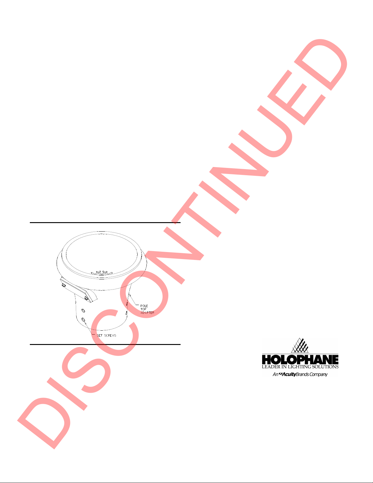
c. Place and level electrical housing on pole. Alternate tightening of
the four set screws will assist in centering the electrical housing on
the tenon. Tighten the four set screws 25 to 30 inch pounds.
Figure 5
GR180C
d. Connect incoming ground wire to ground wire attached to the
inside bottom of wiring chamber. Connect incoming common wire
to wire marked COM which is attached to the ballast assembly. If
a single voltage ballast, check the voltage number on the
remaining wire to verify the ballast voltage. Connect this wire to
the incoming supply line. Note: Lead may need to be stripped. If
a multi tap ballast, find the correct voltage marked on one of the
remaining wires and make the connection. Carefully place
connections in wiring chamber for future access.
e. Replace gasket and access cover.
f. Install the proper lamp type. Tighten the lamp carefully but
securely.
g. Wipe the gasket and seal area with a clean, dry cloth to ensure a
proper seal.
OPTICS ORIENTATION NOTES
Some of the fixtures in this series are equipped with optical
components that produce distributions of light that are not symmetric
and are intended to be aimed by orienting the prismatic refractor a
specific direction. The “Street Side” marking on the refractor should
be pointed toward the street.
h. Install refractor onto electrical housing. Verify that the lip on the
refractor slips past the optics mounting clips on the electrical
housing. See Figures 2 and 3. Tighten the optics mounting clip
screws.
i. Energize the fixture and check for proper operation.
3. MAINTENANCE
3.1 Re-lamping and Cleaning
3.1.1 Wipe off exterior dirt and debris from the plastic surfaces
using a soft, clean cloth.
CAUTION
DO NOT USE ABRASIVE CLEANSERS ON OPTICAL SURFACES.
THEIR USE MAY RESULT IN THE LOSS OF OPTICAL
EFFICIENCY.
3.1.2 Note the orientation of the “Street Side” marking on the glass
refractor. Loosen the optic mounting clip screws. Lift the glass
refractor off of the electrical housing. See Figures 2 and 3.
3.1.3 Remove the lamp and dispose of it in a safe and proper
manner.
3.1.4 Install the proper lamp type. Tighten the lamp carefully but
securely.
3.1.5 Install glass refractor onto electrical housing. Verify the optics
are oriented the same as previously installed. Verify that the lip on
the glass refractor slips past the optics mounting clips on the
electrical housing. See Figure 2 and 3. Tighten the optics mounting
clip screws.
3.1.6 Energize the fixture and check for proper operation.
3.2 Electrical Component Replacement.
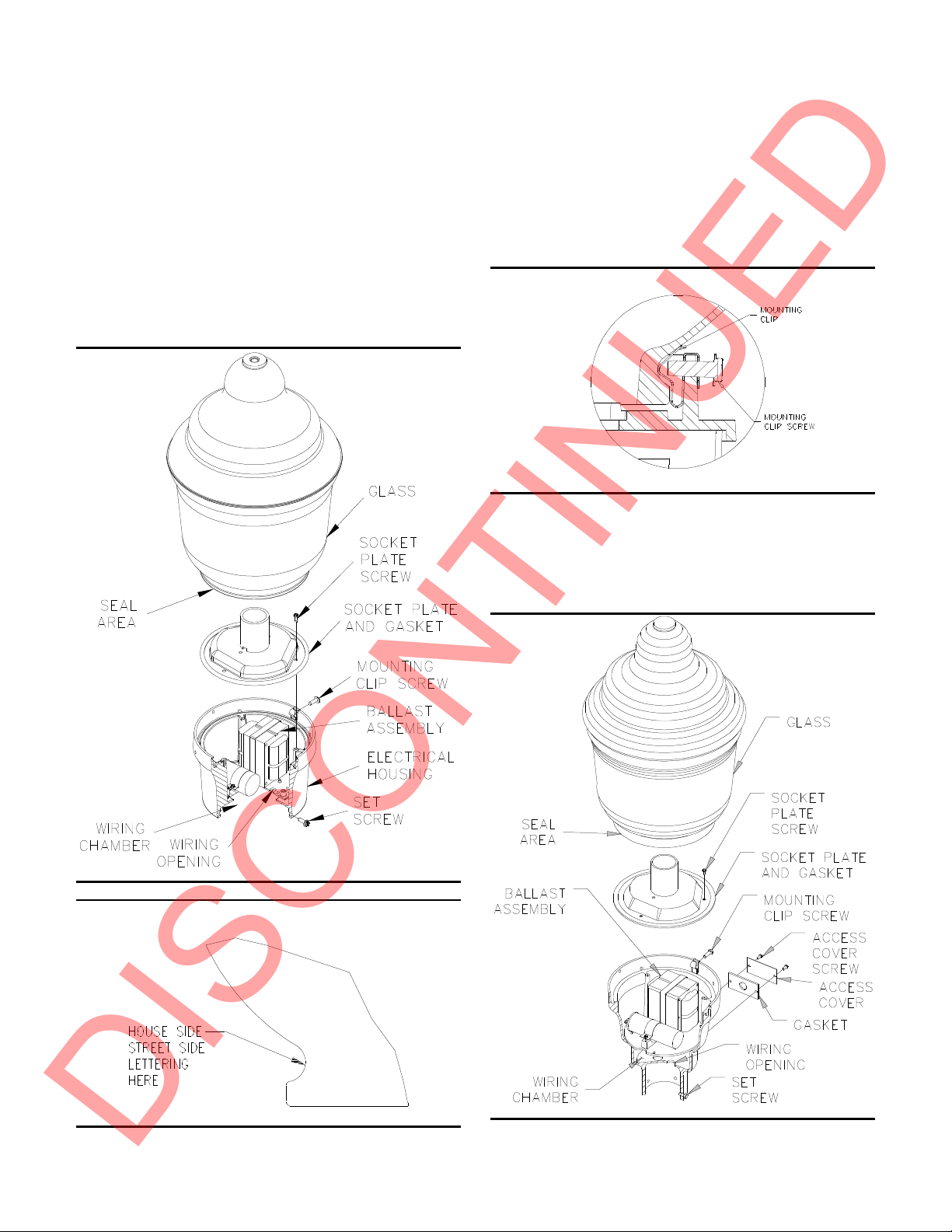
3.2.1 Replacement for Arcadian, Fluted, and
Octagonal Style. Refer to Figures 1, 2, 3, and 6.
a. Wipe off exterior dirt and debris.
b. Loosen the four mounting clip screws holding refractor assembly
to electrical housing.
c. Remove the refractor by lifting it from the housing.
d. Remove lamp.
e. Remove three screws and lift the socket plate and gasket.
f. Remove entire ballast assembly by loosening three screws and
rotating assembly.
g. Tag and disconnect common and line leads.
h. Remove and retain component mounting hardware.
i. Tag associated electrical leads, and remove involved component.
j. Install new component using existing retained mounting hardware.
k. Make electrical connections in accordance with tags and
approved wiring practices.
l. Reinstall ballast assembly, rotate until screws engage plate, and
tighten screws.
m. Reconnect incoming supply leads.
n. Replace socket plate and gasket using the existing screws.
o. Reinstall the lamp.
p. Wipe off gasket area with clean, dry cloth to ensure a proper seal.
q. Install refractor onto electrical housing. Verify the optics are
oriented the same as previously installed. Verify that the lip on the
refractor slips past the optics mounting clips on the electrical
housing. See Figures 2 and 3. Tighten the optics mounting clip
screws.
r. Energize the fixture and check for proper operation.
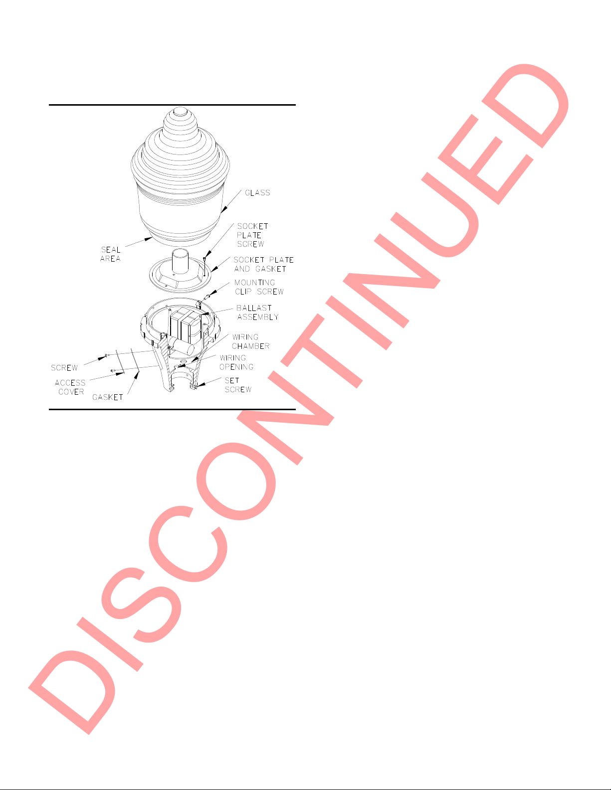
3.2.2 Replacement for Simple and Leaf Style.
Refer to Figures 2,3,4,5.
a. Wipe off exterior dirt and debris.
b. Loosen the four mounting clip screws holding refractor assembly
to electrical housing.
c. Remove the refractor by lifting it from the housing.
d. Remove lamp.
e. Remove three screws and lift the socket plate and gasket.
f. Remove access cover on tenon fitter to provide access to wiring
chamber.
DISCONTINUED

IM-30-G
g. Tag and disconnect common and line leads.
h. Remove and retain component mounting hardware.
i. Tag associated electrical leads, and remove involved component.
j. Install new component using existing mounting hardware.
k. Make electrical connections in accordance with tags and
approved wiring practices.
l. Reconnect incoming supply leads.
m. Replace access cover.
n. Replace socket plate and gasket using the existing screws.
o. Reinstall the lamp.
p. Wipe off gasket area with clean, dry cloth to ensure a proper seal.
q. Install refractor onto electrical housing. Verify the optics are
oriented the same as previously installed. Verify that the lip on the
refractor slips past the optics mounting clips on the electrical
housing. See Figures 2 and 3. Tighten the optics mounting clip
screws.
r. Energize the fixture and check for proper operation.
4. ACCESSORIES
4.1 GV1A73 Pole Top Adaptor for use with
Arcadian, Fluted and Octagonal Styles.
Refer to Figure 6.
4.1.1 Place and level pole top adapter on the pole. Alternate
tightening of the six set screws will assist in centering the adapter on
the tenon. Tighten the four set screws 25 to 30 inch pounds.
4.1.2 Install the luminaire.
Figure 6
GR1044
4. LIMITED WARRANTY AND
LIMITATION OF LIABILITY
The Holophane limited warranty and limitation of liability is published
in the "Terms and Conditions" section of the current Holophane
buyer’s guide, and is available from your local Holophane sales
representative.
®
Acuity Brands Lighting, Inc.
3825 Columbus Rd SW, Granville, OH 43023
IM-30-F, 8/03 ©2010 Acuity Lighting Group Inc.
All Rights Reserved
Visit our web site at www.holophane.com
Printed in USA
DISCONTINUED
This manual suits for next models
4
Other HOLOPHANE Outdoor Light manuals