manuals.online logo
Brands
  1. Home
  2. •
  3. Brands
  4. •
  5. HOLOPHANE
  6. •
  7. Outdoor Light
  8. •
  9. HOLOPHANE W Series Manual

HOLOPHANE W Series Manual

This manual suits for next models

2

Other HOLOPHANE Outdoor Light manuals

HOLOPHANE DORCHESTER LED Manual

HOLOPHANE

HOLOPHANE DORCHESTER LED Manual

HOLOPHANE Dorchester User manual

HOLOPHANE

HOLOPHANE Dorchester User manual

HOLOPHANE V-MAX V2 User manual

HOLOPHANE

HOLOPHANE V-MAX V2 User manual

HOLOPHANE GranVille GR174A Manual

HOLOPHANE

HOLOPHANE GranVille GR174A Manual

Popular Outdoor Light manuals by other brands

Kichler Lighting HELEN 37536 instructions

Kichler Lighting

Kichler Lighting HELEN 37536 instructions

Thorn OXANE L installation instructions

Thorn

Thorn OXANE L installation instructions

esotec Solar Globe Light multicolor 20 operating instructions

esotec

esotec Solar Globe Light multicolor 20 operating instructions

mitzi HL200201 ELLIS Assembly and mounting instructions

mitzi

mitzi HL200201 ELLIS Assembly and mounting instructions

HEPER TILA S AFX 3 Module Installation & maintenance instructions

HEPER

HEPER TILA S AFX 3 Module Installation & maintenance instructions

Designplan TRON 180 installation instructions

Designplan

Designplan TRON 180 installation instructions

Sealey LED37 instructions

Sealey

Sealey LED37 instructions

nordlux VEJERS Mounting instruction

nordlux

nordlux VEJERS Mounting instruction

SImx ELITE LED LHTC637 installation instructions

SImx

SImx ELITE LED LHTC637 installation instructions

GEV CAROLINE 10833 manual

GEV

GEV CAROLINE 10833 manual

WE-EF PFL540 LED Installation and maintenance instructions

WE-EF

WE-EF PFL540 LED Installation and maintenance instructions

HEPER DOGO Side LW6048.585-US Installation & maintenance instructions

HEPER

HEPER DOGO Side LW6048.585-US Installation & maintenance instructions

BEGA 84 253 Installation and technical information

BEGA

BEGA 84 253 Installation and technical information

HEPER LW8034.003-US Installation & maintenance instructions

HEPER

HEPER LW8034.003-US Installation & maintenance instructions

HEPER MINIMO Installation & maintenance instructions

HEPER

HEPER MINIMO Installation & maintenance instructions

LIGMAN BAMBOO 3 installation manual

LIGMAN

LIGMAN BAMBOO 3 installation manual

Maretti TUBE CUBE WALL 14.4998.04 quick start guide

Maretti

Maretti TUBE CUBE WALL 14.4998.04 quick start guide

Maxim Lighting Carriage House VX 40428WGOB installation instructions

Maxim Lighting

Maxim Lighting Carriage House VX 40428WGOB installation instructions

manuals.online logo
manuals.online logoBrands
  • About & Mission
  • Contact us
  • Privacy Policy
  • Terms and Conditions

Copyright 2025 Manuals.Online. All Rights Reserved.

IM-246
HOLOPHANE
HOLOPHANEHOLOPHANE
HOLOPHANE
®
Acrylic
Washington Postlite
®
Installation and
and Prismasphere
®
Maintenance
W – Series Manual
AFTER INSTALLATION DELIVER THIS
MANUAL TO OWNER
Acrylic Washington Prismasphere
GR1453, GR1454
IMPORTANT SAFETY INSTRUCTIONS
WARNING
–READ THESE INSTRUCTIONS
CAREFULLY BEFORE ATTEMPTING TO INSTALL OR
MAINTAIN THIS FIXTURE. WORK MUST BE DONE BY
QUALIFIED PERSONNEL.
WARNING
– BE CERTAIN THAT ALL ELECTRICAL
POWER IS DISCONNECTED FROM THE FIXTURE
BEFORE INSTALLING OR MAINTAINING THE FIXTURE.
WARNING –
FOLLOW LAMP MANUFACTURER’S
OPERATING AND MAINTENANCE INSTRUCTIONS.
FAILURE TO FOLLOW THESE WARNINGS MAY RESULT
IN DEATH, INJURY OR SIGNIFICANT PROPE
1 INTRODUCTION
1.1 Product Description.
1.1.1 The W Series is designed to include most of the standard low
wattage medium and mogal base HID lamps currently available.
1.1.2 The W Series has been designed for easy maintenance and
repair of components.
1.1.3 All electrical component’s are mounted on a plate creating a
replaceable ballast assembly.
1.1.4 Access to the ballast assembly is made by removal of the optics
and socket cover.
1.2 Alternate Information Sources.
Holophane
Field Service Department
P.O. Box 3004
Newark, OH 43058-3004
(866) 759-1577
2 INSTALLATION
2.1 Tools and Materials Required.
TABLE 1. Installation Tools and Materials
DESCRIPTION USE
3/16” Allen wrench 3/8” set screws in housing
¼” nutdriver or medium Socket cover, ballast plate
slotted screwdriver
Torque wrench Set screws
Pliers Thumb screws
2.2 Electrical Assembly Installation
2.2.1 Remove screws holding socket cover in place. Disconnect
socket connection and set aside socket cover. (See Figure 1)
2.2.2 Loosen the two screws to the electrical assembly. Firmly grasp
electrical assembly, rotate and lift out thru the keyhole slots. Set
electrical assembly aside. If luminaire has the button photocontrol,
disconnect it’s connection before setting aside.
2.2.3 Place and level housing on pole. Alternate tightening of the six
set screws will assist in centering the housing on the tenon. Tighten
the six set screws to 15 foot pounds.
2.2.4 Carefully place electrical assembly on its side on the top of the
housing and connect incoming ground wire to position L2 to terminal
block. Connect incoming common wire to position L3 to terminal
block. Connect incoming supply line to position L1 to terminal block.
Reconnect photocontrol if supplied.
2.2.5 Carefully place the electrical assembly back into the housing
and into the keyhole slots of the electrical plate watching not to pinch
any wires. Rotate electrical assembly and tighten the two screws.
2.2.6 Reconnect the lamp connection and place the socket cover
back onto the housing securing with the two screws previously
removed.
2.2.7 Install the proper lamp as specified on Nameplate Label.
Tighten the lamp carefully but securely.
2.2.8 Wipe the gasket and seating area of the optics with a clean dry
cloth to ensure a proper seal.
OPTICS ORIENTATION NOTES
Some of the luminaries are equipped with optics that produce
distributions of light that are not symmetric and are intended to be
aimed by orienting the prismatic refractor a specific direction. The
“Street Side” marking on the refractor should be pointed toward the
street. See sections 2.3 and 2.4 for Heat Shield and House Side
Shield assemblies.
2.2.9 Install optics onto housing and center. Alternate tightening
thumb screws until each screw is tightened all the way seating flat
portion the screw head with housing side. It may be helpful to use
pliers to tighten these screws.
2.2.10 Energize the luminaire and check for proper operation.
IM-246
Figure 1
GR1455
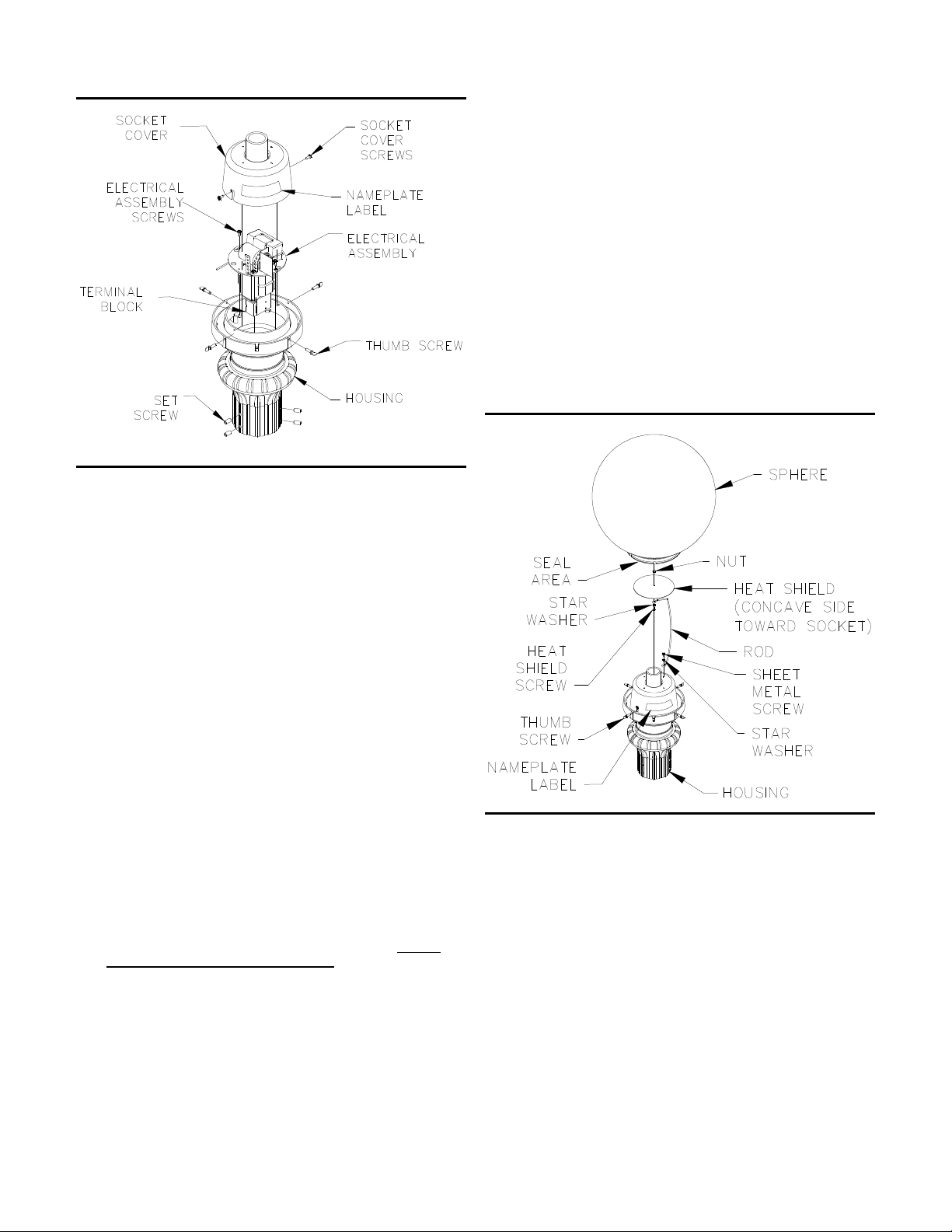
2.3 Prismasphere Optic Assembly Installation
2.3.1 Once housing has been installed according to instructions
in Section 2.2 and before placing the Sphere optics onto the
housing, the heat shield must be assembled onto the socket
cover.
2.3.2 Attach heat shield to rod using washer, nut and machine
screw as shown in Figure 2. (Note, the concave side of heat
shield must be toward socket.) Mount opposite end of rod to any
hole on top of socket cover using sheet metal screw and washer.
Rod, washers, shield, nut and screws are shipped in a plastic
bag with the housing assembly.
2.3.3 Install the proper lamp as specified on Nameplate Label.
Tighten the lamp carefully but securely.
2.3.4 Wipe the gasket and seating area of the optics with a clean
dry cloth to ensure a proper seal.
2.3.5 Install optics onto housing and center. Alternate tightening
thumb screws until each screw is tightened all the way seating
flat portion the screw head with housing side. It may be helpful to
use pliers to tighten these screws.
2.3.6 Energize the luminaire and check for proper operation.
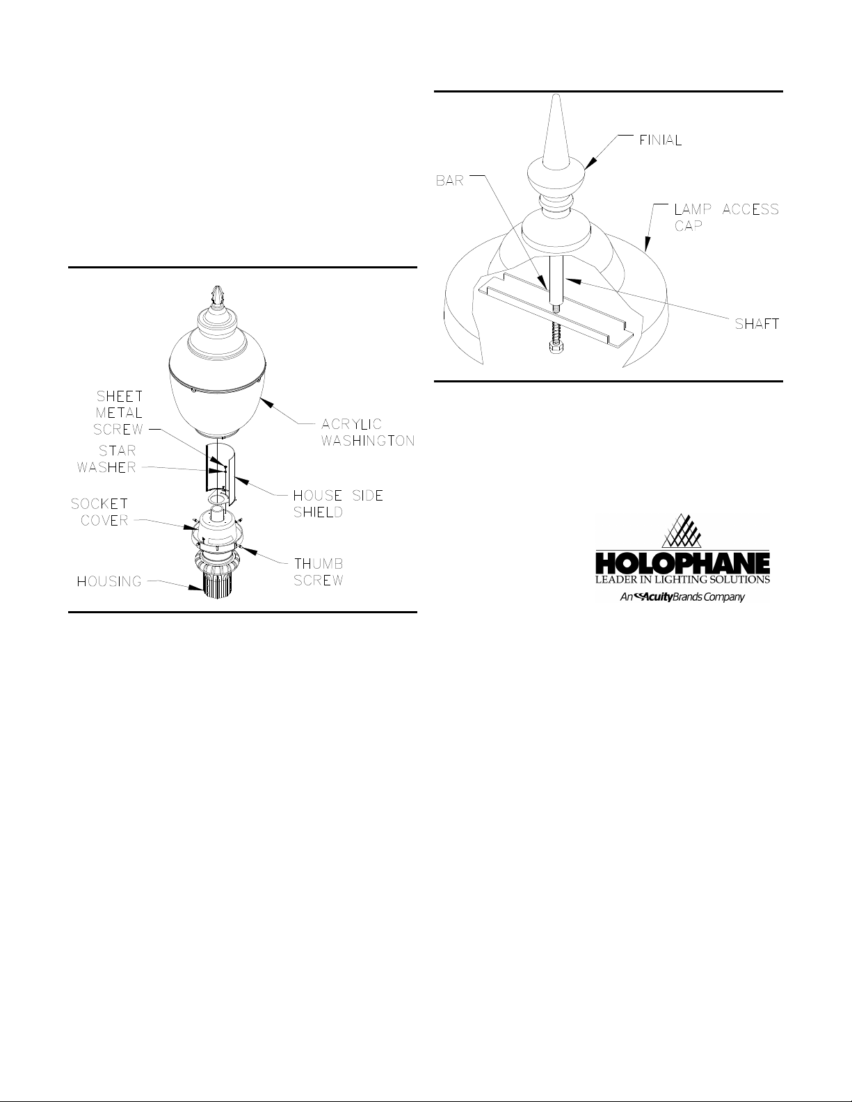
2.4 Acrylic Washington Optic Assembly with
House Side Shield Installation
2.4.1 Once housing has been installed according to instructions
in Section 2.2 and before placing the Acrylic Washington Optics
onto the housing, the house side shield must be assembled on to
the socket cover.
2.4.2 Attach heat shield to socket cover using sheet metal screw
and washer as shown in Figure 3. Mount house side shield to
any hole on top of socket cover to achieve the desired position
for house shielding using sheet metal screw and washer. Utilize
the slot in the base of the shield for better positioning. House
side shield must be installed before lamp. House side shield,
washer and screws are shipped in a plastic bag with the housing
assembly.
2.4.3 Install the proper lamp as specified on Nameplate Label.
Tighten the lamp carefully but securely.
2.4.4 Wipe the gasket and seating area of the optics with a clean
dry cloth to ensure a proper seal.
2.4.5 Install optics onto housing and center. Alternate tightening
thumb screws until each screw is tightened all the way seating
flat portion the screw head with housing side. It may be helpful to
use pliers to tighten these screws.
2.4.6 Energize the luminaire and check for proper operation.
3
MAINTENANCE
Electrical Component Replacement
.
3.1.1 Wipe off exterior dirt and debris.
3.1.2 Remove the four mounting thumb screws holding refractor
assembly to electrical housing.
3.1.3 Remove the refractor by lifting it from the housing.
3.1.4 Remove screws holding socket cover in place. Disconnect
socket connection and set aside socket cover. (See Figure 1)
3.1.5 Loosen the two screws to the electrical assembly. Firmly grasp
electrical assembly, rotate and lift out thru the keyhole slots. Set
electrical assembly aside. If luminaire has the button photocontrol,
disconnect it’s connection before setting aside.
3.1.6 Tag and disconnect common and line leads.
3.1.7 Remove and retain component mounting hardware.
3.1.8 Tag associated electrical leads, and remove involved
component.
3.1.9 Install new component using existing mounting hardware.
3.1.10 Make electrical connections in accordance with tags and
approved wiring practices.
3.1.11 Reconnect incoming lead lines and install optics as instructed
in Section 2.2.
Figure 2
GR1456
4 RELAMPING AND CLEANING.
4.1. Lamp Access
4.1.1 Standard Units:
Note the orientation of the “Street Side” marking on the refractor.
Loosen the optic mounting thumb screws. Lift the refractor off of the
housing.
Units with Top re-lamping access:
Grip the finial on top of the fixture, rotate it counter clockwise until the
bar is free from threads on shaft. Lift up on finial, shift bar to one side
and remove lamp access cap. See Figure 4
4.1.2 Remove the lamp and dispose of it in a safe and proper
manner.
4.1.3 Install the proper lamp type as specified on Nameplate Label.
Tighten the lamp carefully but securely.
IM-246
4.2 Replace Lamp Access
4.2.1 Standard Units:
Install refractor onto electrical housing. Verify the optics are oriented
the same as previously installed. Tighten the optics mounting thumb
screws.
Units with Top re-lamping access:
Install the lamp access cap by inserting the clamp bar under flange of
refractor, rotate the finial clockwise until the clamp bar becomes tight
against refractor. See Figure 4.
4.2.2
Energize the fixture and check for proper operation
Figure 3
GR1457
Figure 4
GR840A
5 Limited Warranty and Limitation of Liability
The Holophane limited warranty and limitation of liability is published
in the "Terms and Conditions" section of the current Holophane
buyer's guide, and is available from your local Holophane sales
representative.
®
Acuity Lighting Group, Inc.
214 Oakwood Ave., Newark, OH 43055
IM-246 1/04 ©2004 Acuity Lighting Group Inc.
Visit our web site at www.holophane.com
Printed in USA