Holtek WAS-2271EN User manual

2.4GHz Self-powered Wireless Doorbell
WAS-2271EN V1.00 1 / 12 December 12, 2022
2.4GHz Self-powered Wireless Doorbell
D/N: WAS-2271EN
Introduction
Self-powered wireless doorbells use radio transmission and which provide the doorbell power
supply using a self-powered architecture, without requiring wiring and a battery power source. Self-
powered wireless doorbells include two parts, a transmitter to send a doorbell signal and a
transponder to receive the signal and then provide a response to generate a doorbell sound.
For such applications, Holtek has a 2.4GHz self-powered wireless doorbell solution. Here the
doorbell uses a self-powered architecture combined with a 2.4GHz transmitter-only device, the
BC5161. The transponder uses a 2.4GHz receiver module, the BM5602-60-1, and a microcontroller
with an integrated voice function, the HT66FV140.
Figure 1. System Block Diagram
Applications
Wireless doorbells, wireless ordering bells, wireless switches.

2.4GHz Self-powered Wireless Doorbell
WAS-2271EN V1.00 2 / 12 December 12, 2022
Solution Features
1. Reduced component requirements: integrated transmitter, receiver and audio function.
The doorbell transmitter device includes an integrated 2.4GHz GFSK transmitter and an
encoder. The transponder receiver device includes an integrated 2.4GHz transceiver and a
baseband modem. The transponder master MCU includes an integrated 16-bit D/A converter, a
power amplifier and digital programmable volume control.
2. Good RF characteristics: high power, high sensitivity, high data rate and high anti-interference.
The BC5161 transmitter has a maximum output power of +8dBm. The BM5602-60-1 receiver,
which includes an integrated device, the BC5602, has a high sensitivity of -97dBm. In addition,
these devices are used to implement a high transmission data rate of 125/250/500Kbps. This
also allows operation in the 2402~2480MHz frequency bands, greatly improving the anti-
interference ability using a frequency hopping architecture.
3. Low power consumption, environmentally friendly: self-powered architecture.
The doorbell uses a self-powered architecture. Instead of the usual battery power, this solution
eliminates the drawbacks of battery replacement providing a more environmentally friendly
solution, which is enough to meet the requirements for low power wireless applications.
Operating Principle
This self-powered doorbell provides a wireless bell ring or alarm function without requiring a
transmitter battery. The doorbell transmitter is usually located outside on the door. When a visitor
presses the power generating device button on the doorbell, the kinetic energy generated from the
pushing action will be converted into electrical energy. This is used to drive a low-power RF device
to generate a packet of data which is then modulated onto an RF signal. The transponder is usually
located indoors, which will receive the transmitted data and then trigger a bell or ringtone which is
generated using the audio amplifier. Alternatively it can also be used to raise an alarm.
Figure 2

2.4GHz Self-powered Wireless Doorbell
WAS-2271EN V1.00 3 / 12 December 12, 2022
Functional Description
Solution Features
The reference design is composed of a doorbell transmitter and a transponder, both of which will
be described below.
Doorbell
Operating voltage: AC > 2.0V
Operating current: 19mA – self generating 200μJ allows the transmission of 14 consecutive
data packets
Transmission power: 5dBm
Power supply mode: self-powered architecture, without requiring battery replacement
Transponder
Operating voltage: AC 220V
Standby power consumption: 0.6W
5-level volume: 2.5dB, 3.0dB, 3.5dB, 4.0dB and 4.5dB
Number of connected doorbells: up to 4
Power supply mode: 220V/50Hz
Solution Functions
The following figures show the outlines for a self-powered doorbell product.
Indicator
Self-powered Architecture
Power Supply Interface
Figure 3. Transmitter Main Components

2.4GHz Self-powered Wireless Doorbell
WAS-2271EN V1.00 4 / 12 December 12, 2022
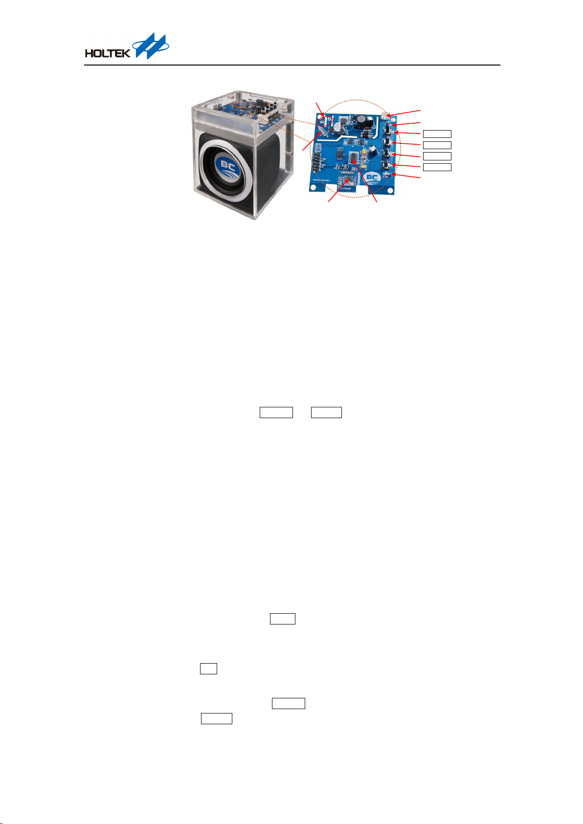
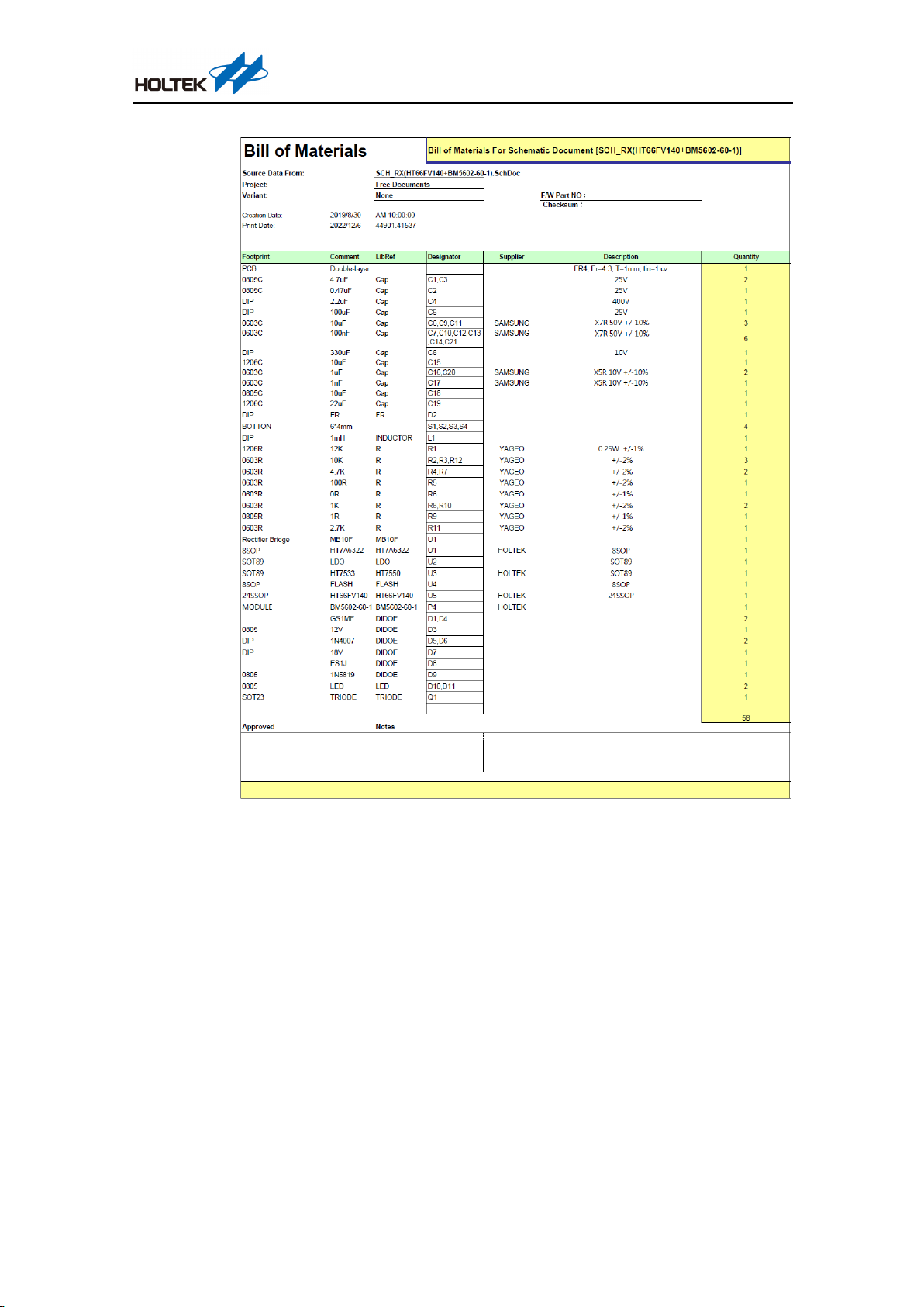
Receiver Module
BM5602-60-1
Master MCU
HT66FV140
Mains
Interface
Fuse
Indicator
Indicator
Audio Output
Interface
Volume+
Swit ch
Stop
Volume-
Figure 4. Transponder Main Components
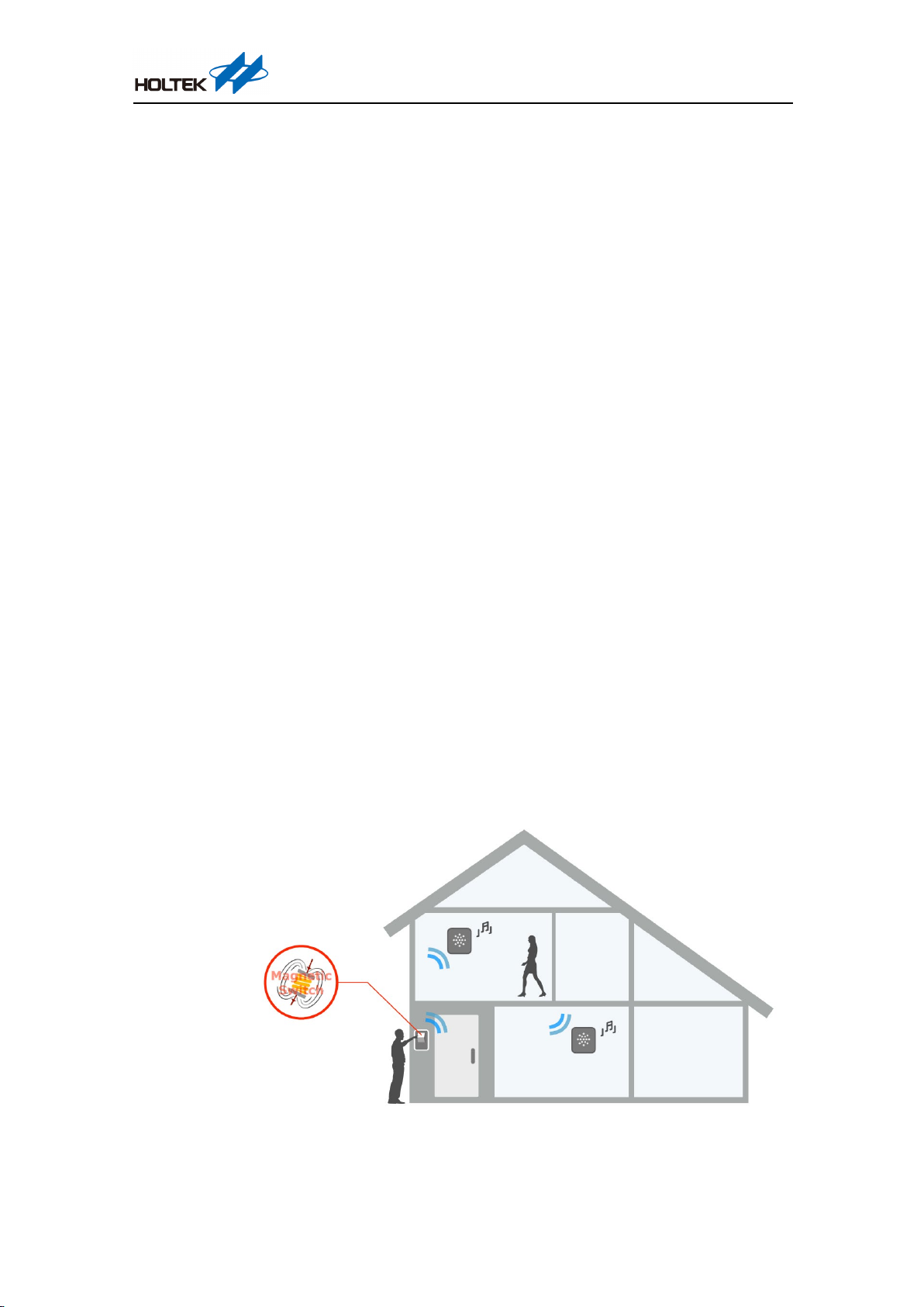
Before use, ensure that the doorbells and transponder have been paired with each other. Each
transponder can pair with a maximum of four doorbells. Therefore, if the fifth doorbell has been
successfully paired to the transponder, the first paired doorbell will be then unavailable. The
transponder only responds to doorbells that have already been paired. Each transmitter has a unique
24-bit ID. Pairings are required to enable the receiver to save the transmitter IDs for identification.
After the transponder has been powered on by the mains supply, if the doorbell is pressed and then
released, it will generate an RF signal. After the transponder receives the RF signal, it will generate
an audio output using the audio amplifier and can also implement other related operations using the
corresponding control keys.
1. Learning the address code
After power-on, press the Volume+ and Vo l u m e - keys simultaneously and then release them,
the LED indicator remains on, which indicates that the receiver has entered the learning address
code mode. Then press the doorbell and the receiver should ring along with a flashing LED to
indicate that the address code has been successfully learned. If no data has been received within
10 seconds, the receiver will exit the learning address code mode. Repeat the above operation
to learn another address code. A single receiver can pair up to four transmitters. When a fifth
address code has been learned, the first paired address code will be discarded and so on.
2. Clear the address code
After power-on, if the learned addresses are required to be cleared, press the Switch and Stop
keys on the receiver simultaneously and then release them. When the LED indicator flashes
three times quickly, this indicates that all the stored address codes have been cleared and that
the address code of the doorbell to be connected should be learned again.
3. Switch the ringtone
On the transponder, press the Switch key and release it to select the next ringtone, or to the first
ringtone if it is the last one.
4. Stop playing the ringtone
Press the Stop key and release it, the transponder will stop playing the ringtone.
5. Volume adjustment
On the transponder, press the Vo l u m e + key and release it to increase the volume by one level.
Press the Volume- key and release it to decrease the volume by one level. In this way it will
switch among five different volume levels.

2.4GHz Self-powered Wireless Doorbell
WAS-2271EN V1.00 5 / 12 December 12, 2022
Reference Design Description
Self-powered doorbells contain a doorbell and a transponder. The doorbell transmitter uses the
BC5161 as the master device to send an RF signal after the self-powered device has been pressed.
The transponder uses the BM5602-60-1 as the receiver module to receive and decode the RF signals
and then transmit the data to the master MCU, the HT66FV140. This will then trigger a bell or
ringtone sound or other actions according to the obtained data information. A hardware description
of the doorbell and transponder will be introduced separately.
Hardware Description
Figure 5. Transmitter Application Circuit
Doorbell transmitters are powered by a push action button which converts the kinetic energy of the
push action to electrical energy. The transmitter will always be in a power off state, thus having
zero power consumption before the self-powered generating device is pressed. When the self-
powered generating device key is pressed, the circuit will store the generated electrical energy on a
capacitor. When the key is released, during the return to its original state, it will also generate energy
again during the release action. At this time, the energy generated by these two actions is converted
using a DC-DC regulator to provide power for the BC5161 transmitting device. Since the D2 pin is
connected to ground, the BC5161 will enter the transmitting state immediately after receiving
power and continue transmitting until the energy is fully consumed after which it will return to the
power off state.

2.4GHz Self-powered Wireless Doorbell
WAS-2271EN V1.00 6 / 12 December 12, 2022
Figure 6. Transponder Application Circuit
The self-powered wireless doorbell transponder is powered by a mains supply and uses the
HT7A6322 as the power control IC, allowing operation from an 85VAC~265VAC power source. A
2.4GHz transceiver module, the BM5602-60-1, is used to process the RF signals, as well as a Flash
MCU, the HT66FV140. The MCU includes an integrated voice play function and can detect the
status of four keys. These keys can correspond to different user actions such as to change the bell
chime, increase or decrease the volume level or to implement the pairing function.
Layout and Hardware Considerations
Figure 7 and Figure 8 show the doorbell transmitter PCB Layout top and bottom layers.
Figure 9 and Figure 10 show the transponder PCB Layout top and bottom layers.
Figure 7
Figure 8

2.4GHz Self-powered Wireless Doorbell
WAS-2271EN V1.00 7 / 12 December 12, 2022
Figure 9
Figure 10
PCB BOM List
Table 1. Transmitter BOM List

2.4GHz Self-powered Wireless Doorbell
WAS-2271EN V1.00 8 / 12 December 12, 2022
Table 2. Transponder BOM List

2.4GHz Self-powered Wireless Doorbell
WAS-2271EN V1.00 9 / 12 December 12, 2022
Software Description
Software Main Flow
Start
Initialisation
Ke y Pre ssed ?Key action
Detect RF communication
status
Playing voice ? Turn off power
amplifi er and LED
RF data received ?
In Pairing mode ?
Play voice,
LED flashes
ID correct ?
St o re ID
Playing voice ?
Yes
No
Yes
Yes
Yes
Yes
Yes
No
No
No
No
No
Play completed ?
Yes
No
Figure 11. Software Main Flowchart
1. Initialisation: After the power-on reset, the program will first execute the system setup
initialisation, RF receiver setup initialisation, timer setup initialisation, etc. Once the
initialisation has completed, it will enter the RF receiving mode.
2. Key action: execute the key scanning operation to check whether any key is pressed. If a key
has been pressed, the program will execute the key action subroutine and then return to the main
loop.
3. Detect RF communication status: The program will set the corresponding flag high according
to the detection result.
4. Check whether a voice is being played: If no voice is being played, it will return to the main
program. If a voice is being played, it will check whether the voice data in the Flash has been
played. If it has been played, it will turn off the internal power amplifier and the external LED
and then return to the main program.

2.4GHz Self-powered Wireless Doorbell
WAS-2271EN V1.00 10 / 12 December 12, 2022
5. Check whether the RF data has been received: If no RF data has been received, return to the
main program and then go back to the key detection step.
6. If the RF data has been received, it will first determine whether it is for the pairing process. If
it is for the pairing process, the ID in the RF data is stored into the EEPROM. It will then
determine if a voice is being played. If no voice is being played, it will play a voice and turn on
the LED. If the voice has finished playing, it will return to the main program and then go back
to the key detection step.
7. If it is not in the pairing process, the saved ID will be read from the EEPROM. If the ID read
out is consistent with the ID in the RF data, it will determine whether the voice is being played.
If no voice is being played, it will start the play, turn on the LED and then go back to execute
key detection. If the IDs are inconsistent, return to the main program and then go back to the
key detection step.
Key Action Flow
Key action
In Pairing mode ?
LED flashes
4 times quickly
Volume+ / Volume-
keys pressed ?
Stop key pressed ?
Switch key pressed ?
Volume+ & Volume-
keys pressed Simultaneously ?
St o p & Switch
keys pressed Simultaneously ?
Stop key pressed ?
At maximum or
minimum volume ?
Volume increase or decrease by 1Play voice,
LED flashes normally
Turn off power amplifier and L ED
Switch to next voice, turn on power
amplifi er, LED flashes
Enter Pairing mode, turn on power
amplifi er, LED remains on
Clear address, turn off power
amplifi er, LED flashes 3 times
End
Stop pairing and
turn off LED
Yes
Yes
Yes
Yes
Yes
Yes
Yes
Yes
No
No
No
No
No
No
No
No
Figure 12. Key Action Flowchart

2.4GHz Self-powered Wireless Doorbell
WAS-2271EN V1.00 11 / 12 December 12, 2022
Status Key Function
Pairing Mode Stop Stop pairing, turn off the LED
Non-pairing
Mode
Volume-
At the minimum
volume level
Play a voice, the LED flashes 4 times quickly and then flashes
normally
Not at the minimum
volume level
Decrease the volume by one level, play a voice, the LED
flashes
Volume+
At the maximum
volume level
Play a voice, the LED flashes 4 times quickly and then flashes
normally
Not at the maximum
volume level
Increase the volume by one level, play a voice, the LED
flashes
Stop Stop playing the voice, turn off the power amplifier, turn off the LED
Switch Switch to the next voice, turn on the power amplifier, the LED flashes
Volume+ &
Volume-
Enter the pairing mode, stop playing the voice, turn off the power amplifier, the LED
remains on
Stop &
Switch
Clear the paired address, stop playing the voice, turn off the power
amplifier, the LED
flashes 3 times
Test Data
Test Item
Theoretical Value
Actual Value
BC5161 TX Transmission Power
5dBm
5.35dBm
BM5602-60-1 RX Sensitivity
-97dBm
-96.5dBm
Working range indoors
—
10m with two walls
Working range outdoors
—
>100m
Table 3
Solution Comparison
Item Holtek Solution (2.4GHz) Traditional Solution (Sub-1GHz)
Frequency
Band
Wide frequency band, supports frequency hopping,
avoids the same frequency interference
Narrow frequency band, cannot avoid the
same frequency interference
Wavelength Short wavelength, short antenna, only a PCB antenna
is required to obtain better effect, with small area
Long wavelength, long antenna, an
additional spring antenna or a long wire is
required to implement better RF radiation
Data Rate High data rate, the same data transmission volume
can be implemented with less power consumption
Low data speed, the same data transmission
volume can be implemented with more
power consumption
Solution SoC SoC / TX+Encode / MCU+TRX IC
Conclusion
This document has introduced a 2.4GHz self-powered doorbell solution implemented using the
Holtek BC5161, BM5602-60-1 and HT66FV140 devices. The BC5161 is a 2.4GHz transmitter
which includes an integrated encoder. The self-powered doorbell function eliminates the need for a
transmitter power source. The BM5602-60-1 is a 2.4GHz GFSK transceiver, which can decode the
RF signals received from the BC5161 transmitter automatically. The HT66FV140 as the master
MCU controls the BM5602-60-1 and reads the data using its SPI interface. This MCU device also
includes an integrated D/A converter, a Class AB power amplifier and programmable digital volume
control. Only a few peripheral components are required to complete the audio play function. In this
way, a complete 2.4GHz self-powered wireless doorbell can be implemented.

2.4GHz Self-powered Wireless Doorbell
WAS-2271EN V1.00 12 / 12 December 12, 2022
Reference Material
Consult the BC5161, BM5602-60-1 and HT66FV140 datasheets.
For more information consult the Holtek website www.holtek.com.
Versions and Modification Information
Date
Author
Issue
Modification Information
2022.08.24 蘇運猛 V1.00 First version
Disclaimer
All information, trademarks, logos, graphics, videos, audio clips, links and other items appearing
on this website ('Information') are for reference only and is subject to change at any time without
prior notice and at the discretion of Holtek Semiconductor Inc. and its related companies
(hereinafter 'Holtek', 'the company', 'us', 'we' or 'our'). Whilst Holtek endeavors to ensure the
accuracy of the Information on this website, no express or implied warranty is given by Holtek to
the accuracy of the Information. Holtek shall bear no responsibility for any incorrectness or leakage.
Holtek shall not be liable for any damages (including but not limited to computer virus, system
problems or data loss) whatsoever arising in using or in connection with the use of this website by
any party. There may be links in this area, which allow you to visit the websites of other companies.
These websites are not controlled by Holtek. Holtek will bear no responsibility and no guarantee to
whatsoever Information displayed at such sites. Hyperlinks to other websites are at your own risk.
Limitation of Liability
In no event shall Holtek Limited be liable to any other party for any loss or damage whatsoever or
howsoever caused directly or indirectly in connection with your access to or use of this website, the
content thereon or any goods, materials or services.
Governing Law
The Disclaimer contained in the website shall be governed by and interpreted in accordance with
the laws of the Republic of China. Users will submit to the non-exclusive jurisdiction of the
Republic of China courts.
Update of Disclaimer
Holtek reserves the right to update the Disclaimer at any time with or without prior notice, all
changes are effective immediately upon posting to the website.
Table of contents
Popular Accessories manuals by other brands

IFM
IFM O5P7 Series operating instructions

Delta Electronics
Delta Electronics Network Device KE Specifications

Badger Meter
Badger Meter SDI Series Installation & operation manual

LMI Technologies
LMI Technologies Gocator 2500 Series quick start guide

NUVE
NUVE EC 160 user manual

Workzone
Workzone DY160121 Quick reference guide