7
www.homewerksww.com
SOLUCIÓN DE PROBLEMAS
PROBLEMA POSIBLE CAUSA ACCIÓN CORRECTIVA
Fugas debajo de manejar. El capuchón se aojó o la junta tórica en el
cartucho está sucia o doblada. 1. Mover la palanca a la posición OFF. Aoje el tornillo de la manija y retire la manija.
2. Apriete el capó girando en sentido horario. Mueva el vástago del cartucho a la posición de
encendido. La fuga debe dejar de escape hacia afuera de todo el vástago del cartucho.
3. Cierre el suministro de agua. Quite el capó girando en sentido antihorario. Levante la válvula del
cartucho. Inspeccione la junta tórica más grande en el capó del cartucho y la junta tórica
pequeña en el vástago del cartucho. Quite toda la suciedad de las juntas tóricas. Si se tuerce
o bien O-ring, enderezarlo. Si bien la junta tórica está dañada, reemplace el cartucho llamando
al servicio al cliente.
4. Coloque el cartucho en el cuerpo del grifo. Asegúrese de que los salientes de los dos lados del
capuchón del cartucho encajen en las ranuras de los dos lados del cuerpo del grifo. Atornille
rmemente el capuchón al cuerpo del grifo.
5. Vuelva a instalar el mango.
El agua no se cierra por completo. Asiento de la válvula de goma está sucio, atascado
o roto. 1. Cierre el suministro de agua para el grifo que gotea.
2. Quite la manija en el lado problema. Aoje el capó girando en sentido antihorario. Levante el
conjunto de cartucho.
3. Inspeccione el asiento de la válvula de goma en el cuerpo del grifo. Si hay escombros o desechos
de cobre en la supercie del asiento, retírelo. Si el asiento de goma se pega rmemente en el
oricio de entrada de agua, empuje suavemente con la yema del dedo para que se mueva hacia
arriba y hacia abajo suavemente. El resorte (más pequeño extremo hacia arriba) debe ser
reemplazado por debajo del asiento de la válvula. Si el asiento de la válvula de goma está
desgastado o roto, reemplace el cartucho llamando al servicio al cliente.
4. Sustituya el cartucho en el cuerpo del grifo. Asegúrese de que los salientes de los dos lados del
capuchón del cartucho encajen en las ranuras de los dos lados del cuerpo del grifo. Atornille
rmemente el capuchón al cuerpo del grifo.
5. Vuelva a colocar el mango.
La llave tiene ltración alrededor del
aireador. Aireador incorrectamente instalado. 1. Destornille el aireador girándolo hacia la derecha. Inspeccione el empaque de caucho negro
en el interior del aireador. La junta de goma debe ser plana.
2. Atornille el aireador sobre el extremo del surtidor y apriete.
Modelo del agua inadecuada. Aireador partes sucias o pequeñas dentro aireador
mal instalados. 1. Quite el aireador del extremo del pico girando en sentido horario.
2. Enjuague suavemente las piezas pequeñas en el interior del aireador para eliminar cualquier
residuo.
3. Vuelva a instalar las piezas pequeñas, como se muestra en el diagrama de despiece. Pantallas
de metal deben ser planas y partidario de plástico deben vser rectas.
4. Atornille el aireador sobre el extremo del surtidor y apriete.
CUIDADO Y MANTENIMIENTO
Limpie periódicamente con un paño suave. Evite limpiadores abrasivos, estropajo de acero y químicos cáusticos porque podrían dañar el terminado y anular la garantía.
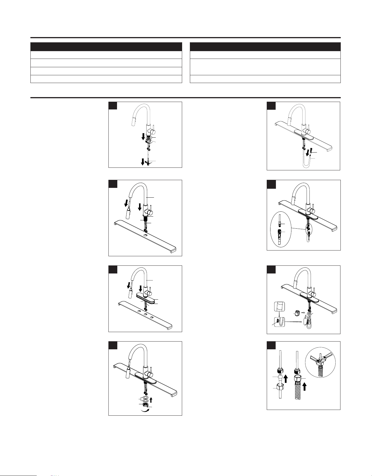
INSTRUCCIONES DE MONTAJE
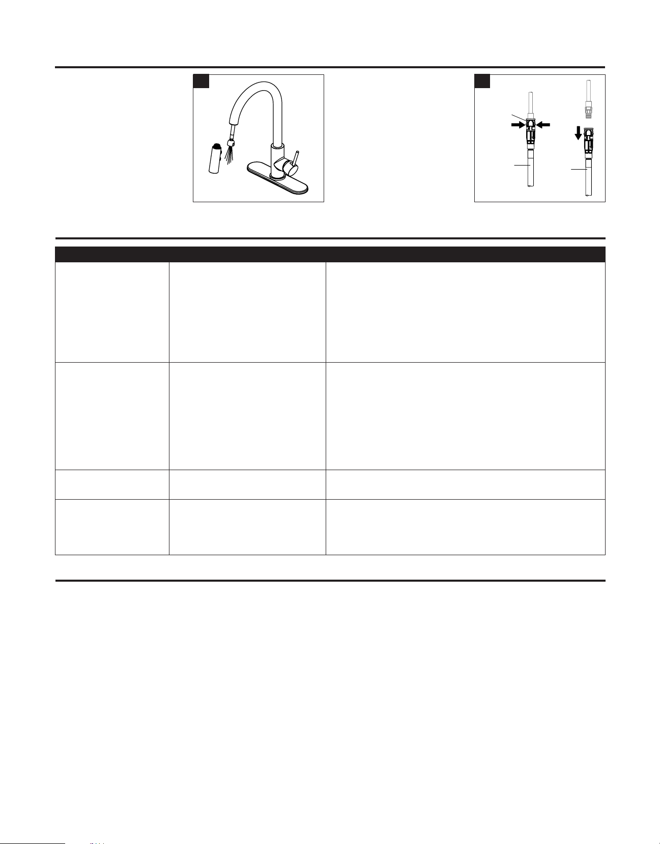
9. IMPORTANTE: Una vez completada
la instalación, abra los suministros de
agua caliente y fría. Compruebe si hay
fugas. Saque el conjunto de la manguera
de la boquilla y retire el cabezal rociador
desenroscándolo de la manguera en
sentido contrario a las agujas del reloj.
Asegúrese de mantener el extremo de la
manguera hacia abajo en el fregadero y
gire el grifo a la posición cálida donde se
mezcla agua caliente y fría. Enjuague las
líneas de agua por un minuto. Esto
elimina cualquier residuo que pueda
causar daños a las partes internas.
Compruebe si hay fugas. Vuelva a apretar
las conexiones si es necesario, pero no
las apriete demasiado. Vuelva a instalar el
cabezal de rociado apretándolo a mano
en la manguera del rociador en el
sentido de las agujas del reloj.
910. Retire el Conector Rápido:
Si es necesario quitar el conector
rápido (1), presione las lengüetas (2) en
el conector rápido y luego tire hacia
abajo para desconectar. Pull
down
11
2
Squeeze
10