and Elevation you got from http://home2us.com/b2c/content/satellite-locator).
Satellite Dish Installation Manual (Ver. 1)
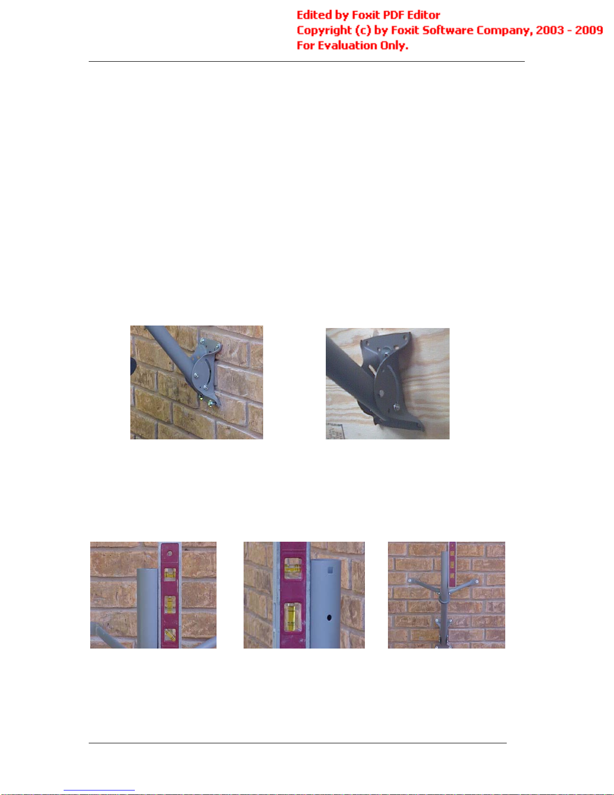
Section 5: Wall-Mounting the Mast Bracket
First, find a smooth surface with a clear view of the satellite (refer to the Azimuth
Masonry: (See Figure 8) Drill a 5/16” pilot hole through the upper left hole in the
bracket with the masonry bit. Using a torpedo level, make sure the bracket is
perfectly level and plumb. Drill the remaining three (3) holes, and then insert
four (4) 5/16” x 1 ½” red head anchors for masonry walls.
Wood: (See Figure 9) Drill a 5/16” pilot hole through the upper left hole in the
bracket with a wood bit. Using a torpedo level, make sure the bracket is
perfectly level and plumb. Drill the remaining three (3) holes, and then insert
four (4) 5/16” x 1 ½” lag bolts.
Note: The lag bolts and anchors are not supplied with the antenna.
Figure 8 Figure 9
Attach the pole to the bracket you mounted with one (1) ¼” x 2 ¼” hex head cap
bolt with ¼” hex nut through the bracket and pole. At this time, simply hand-
tighten to allow for adjustments. Using the torpedo level, adjust the pole so that
the vertical section is level and plumb (refer to Figures 11 and 12).
Figure 11 Figure 12 Figure 13
Attach the clamp and side brackets using one (1) 5/16” x 3” hex screw with 5/16”
hex nut and two (2) lag bolts for either wood or concrete as required (refer to
Figure 13). Make sure the pole is level and plumb and then tighten everything
down.
8