3
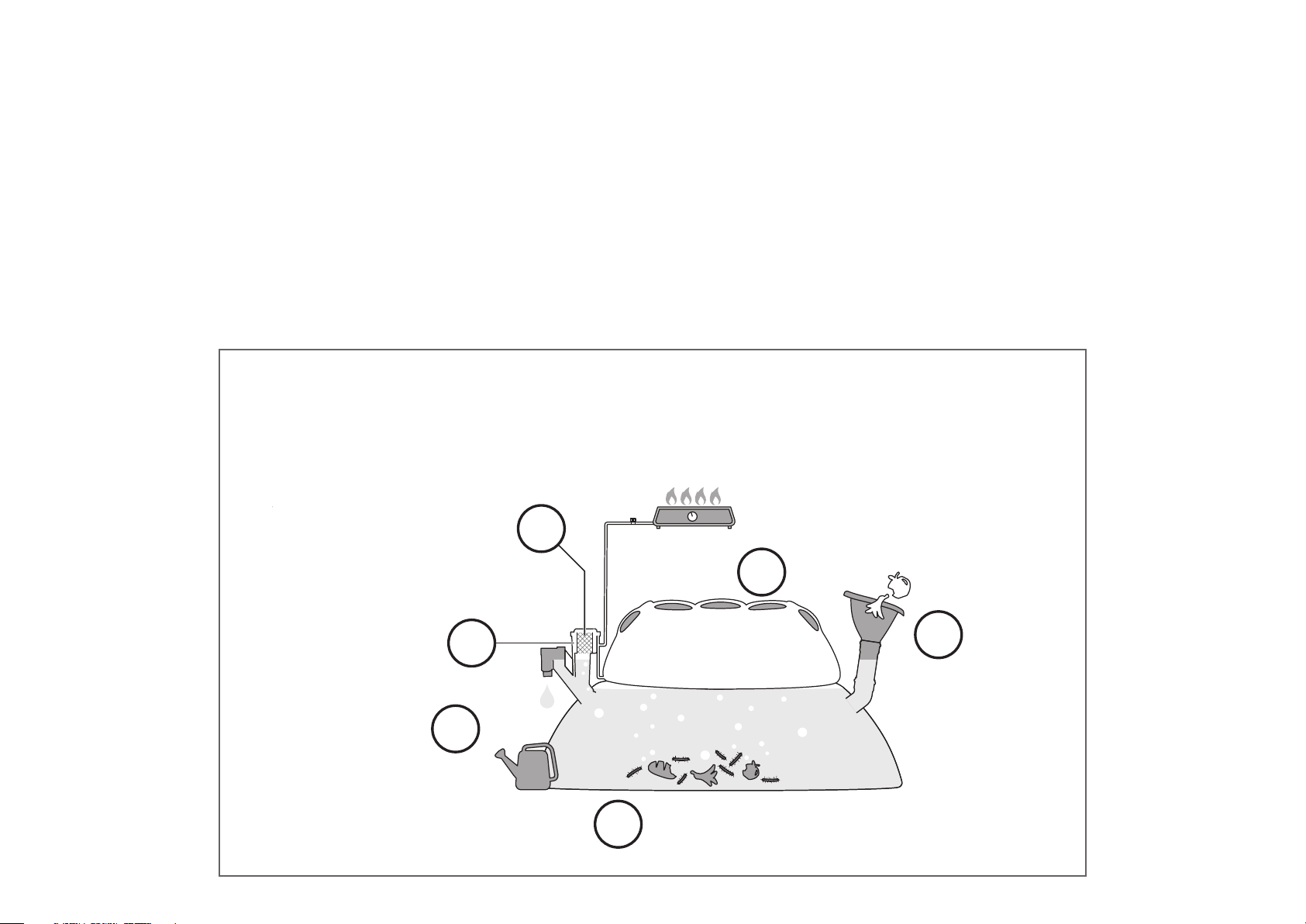
The anaerobic bacteria in the digester
biodegrade the organic waste, producing
biogas in the process.
In addition to biogas, the
system produces a
nutritious, natural fertilizer.
A patented mechanism regulates gas
pressure when the biogas is used, enabling a
steady, even pressure at the end device.
The generated biogas passes through an
active filter to remove any unpleasant odors
and trace amounts of hydrogen sulfide, and
is stored in the gas tank.
A special pressure release
mechanism releases excess
gas once the gas tank is filled
to capacity.
Organic waste is fed into
the digester tank, which
is filled with water.
1
2
5
3
4
6
introduction
The HOMEBIOGAS household biogas system turns organic waste like food scraps and animal manure into biogas, which can
be used for cooking, and natural liquid fertilizer, which can be used for gardening.
Biogas is generated in the system by the anaerobic (without oxygen) fermentation of organic matter. Biogas is a ammable
gas that is lighter than air, composed mainly of methane and carbon dioxide.
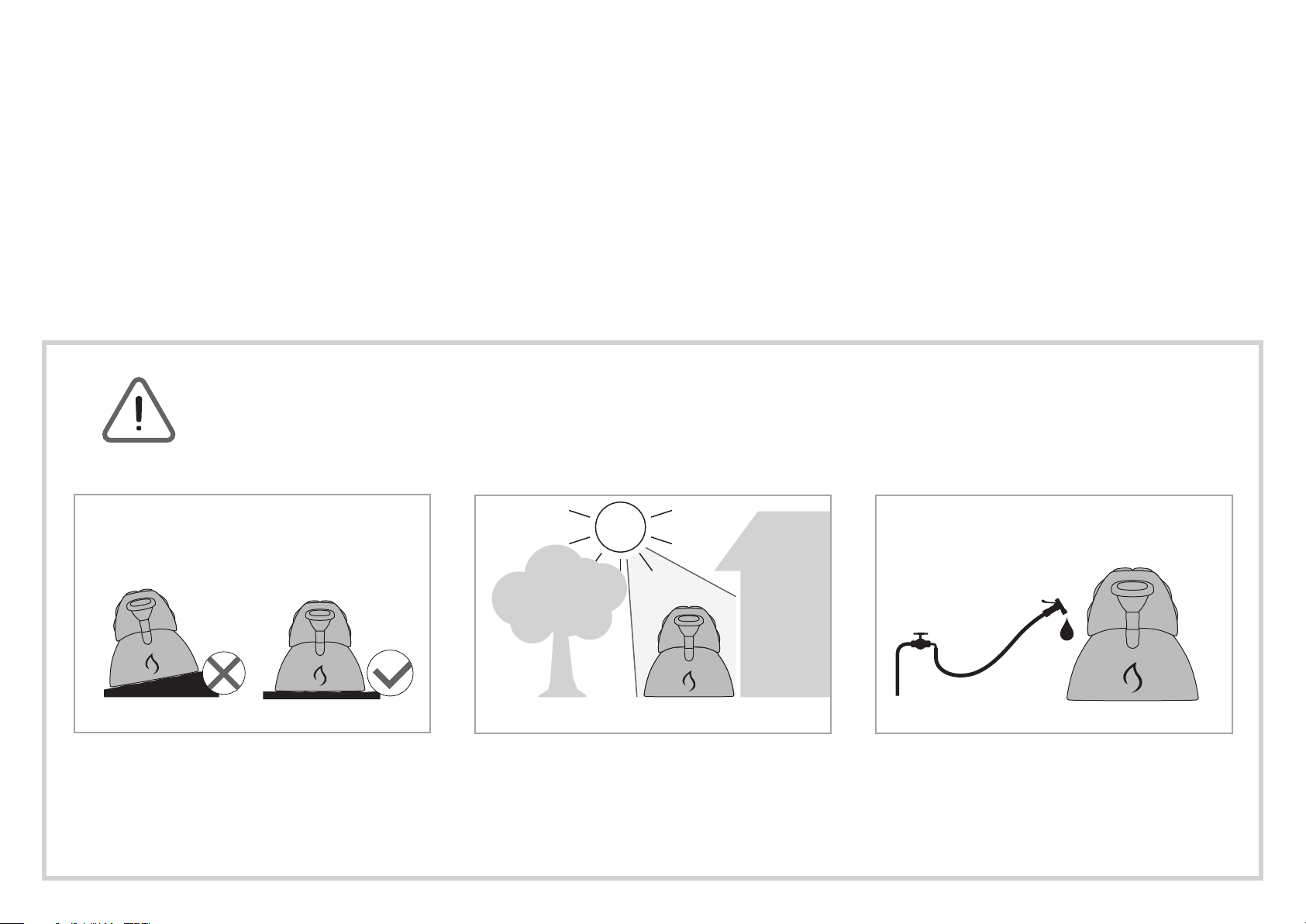
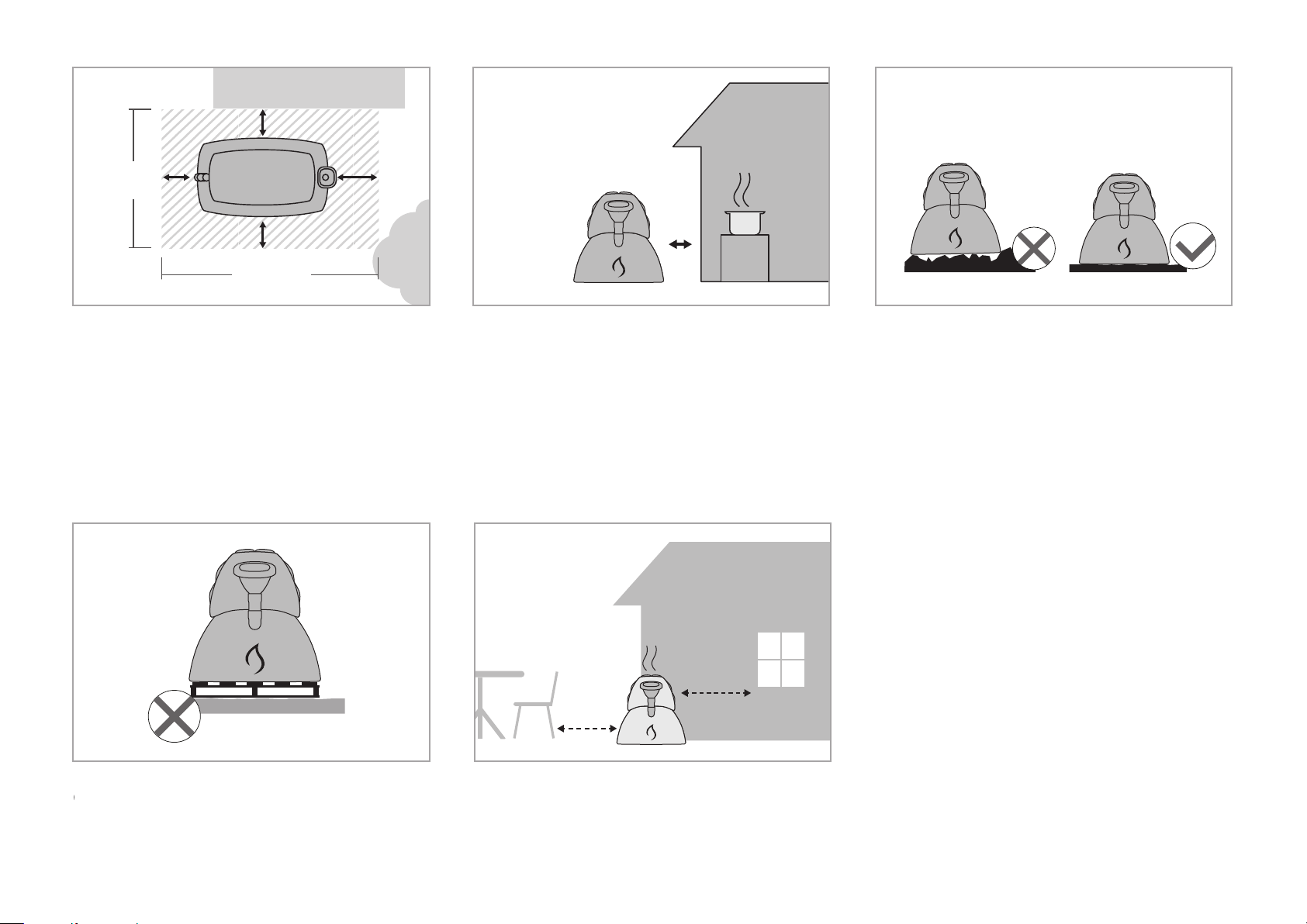
HomeBiogas is a biological system: performance is aected by environmental conditions and may vary due to physical
location and ambient temperature.
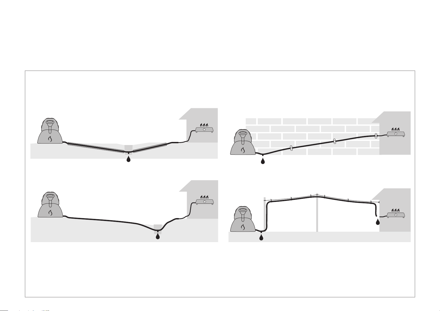
The system operates as a continuous-ow system: organic waste is fed into one end, and gas
and fertilizer are emitted constantly from the other as long as the system is active and being
fed. (Fertilizer is produced whenever liquid & waste are added into the system)
Organic waste is fed into
the digester tank, which is
lled with water.
The anaerobic bacteria in the digester
biodegrade the organic waste, producing
biogas in the process.
In addition to biogas, the
system produces a nutritious,
natural fertilizer.
A special pressure release
mechanism releases excess
gas once the gas tank is lled
to capacity.
The generated biogas passes through
an active lter to remove any unpleasant
odors and trace amounts of hydrogen
sulde, and is stored in the gas tank.
A patented mechanism regulates gas pressure
when the biogas is used, enabling a steady, even
pressure at the end device.