Honeybee AirFLEX User manual

Quick Start Guide
2017
®
This guide is a supplement to the operators manual, do
not aempt to operate your equipment without rst
reading and understanding the full operator manual.
When you exit the combine, shut o the combine,
engage the parking brake, and wait for all moving parts
to come to a complete stop before approaching the
header.
If working on a raised header, ensure the feeder house
cylinder locks are in place.
Do not wear loose clothing or jewelry around moving
parts.
Avoid high pressure hydraulic spray. Seek medical
aenon immediately if it punctures your skin.
Ensure all equipment is secured against sudden drops.
Read and understand all safety instrucons in the
operator manual before proceeding.
Revision 2.2 P/N: 201827

This page intenonally le blank

Page 3 Revision 2.2 P/N: 201827
Honey Bee Manufacturing Ltd.
AirFLEX Header - Quick Start Guide
Header Preparaon
Raise front reel bats to
operaonal posion and
secure to the control arms
using the preinstalled nut and
bolt.
Remove and store the e-down brackets located
on the transport mounng bracket and strut on
the le side of the header.
Reinstall the ngs which secure the paddle pivot
pin.
Remove the wire holding the reel arms
and reel in place. Inspect thoroughly as
the wires can be in mulple locaons.
Ensure dividers are
securely installed

Page 4 Revision 2.2 P/N: 201827
Honey Bee Manufacturing Ltd.
AirFLEX Header - Quick Start Guide
Mounng the Header 1 Release the two transport cart locks and disconnect
the cart’s electrical harness.
2 Release the draw bar lock and disconnect it’s
electrical harness.
3 Slowly drive the combine forward unl the feeder
house is inserted into the feeder house opening.
Ensure it is properly aligned
4 Slowly li the header 1-2 feet above its current
posion to release the transport cart & drawbar.
5 Shut down the combine, engage the parking brake
and engage the feeder house locks.
6 Lower the transport cart support bar and secure pin.
7 Lower the trasport cart with the hand crank and
unhook the straps from the header.
8 Raise the header and back away from the cart,
lower the header back down to a working height.
9 Shut down the combine, engage the parking brake
and engage the feeder house locks.
AB
C

Page 5 Revision 2.2 P/N: 201827
Honey Bee Manufacturing Ltd.
AirFLEX Header - Quick Start Guide
Secure the transport cart and draw bar cart together, secure
with pins as illustrated and place in a storage locaon.
Lower all roller sensors to their operaonal posion.
Evenly adjust the le and right eye bolts on the feed auger drum
so it is moved to within 1/2”(1.3 cm) of the combine feeder
house protrusions.
Set the feed auger drum upper and lower stop bolts to prevent
the drum from contacng the rest of the header (ensure
distance A is less than distance B).
Rotate the auger drum by hand to ensure it will not contact the
protrusions, ghten the lock nuts on the eye bolts.
Set Feed Auger nger ming so the feed auger ngers maintain
adequate clearance from the components surrounding the feed
auger drum.
Check All Clearances around the feed auger drum and adjust
accordingly.
10 11
Finish Mounng
12 16

Page 6 Revision 2.2 P/N: 201827
Honey Bee Manufacturing Ltd.
AirFLEX Header - Quick Start Guide
Make Connecons
1 Turn o the combine’s master baery switch.
2 Make the hydraulic and electrical
connecons at the mulcoupler
located on the le side of the
feeder house. Connect both
drive shas to the combine.
3 Starng at the front of the combine, route
the automax harness under the combine
cab and inside. Connect to the automax
display. Route the remianing poron of the
harness to the combine’s baery. Connect
the harness to the power system aer the
power switch to ensure the Automax does
not drain the baery when the combine is
turned o.
Ensure enough slack is le in the electrical
harness at the feeder house pivot for it to go
through its full range of moon.

Page 7 Revision 2.2 P/N: 201827
Honey Bee Manufacturing Ltd.
AirFLEX Header - Quick Start Guide
Header Calibraon Overview
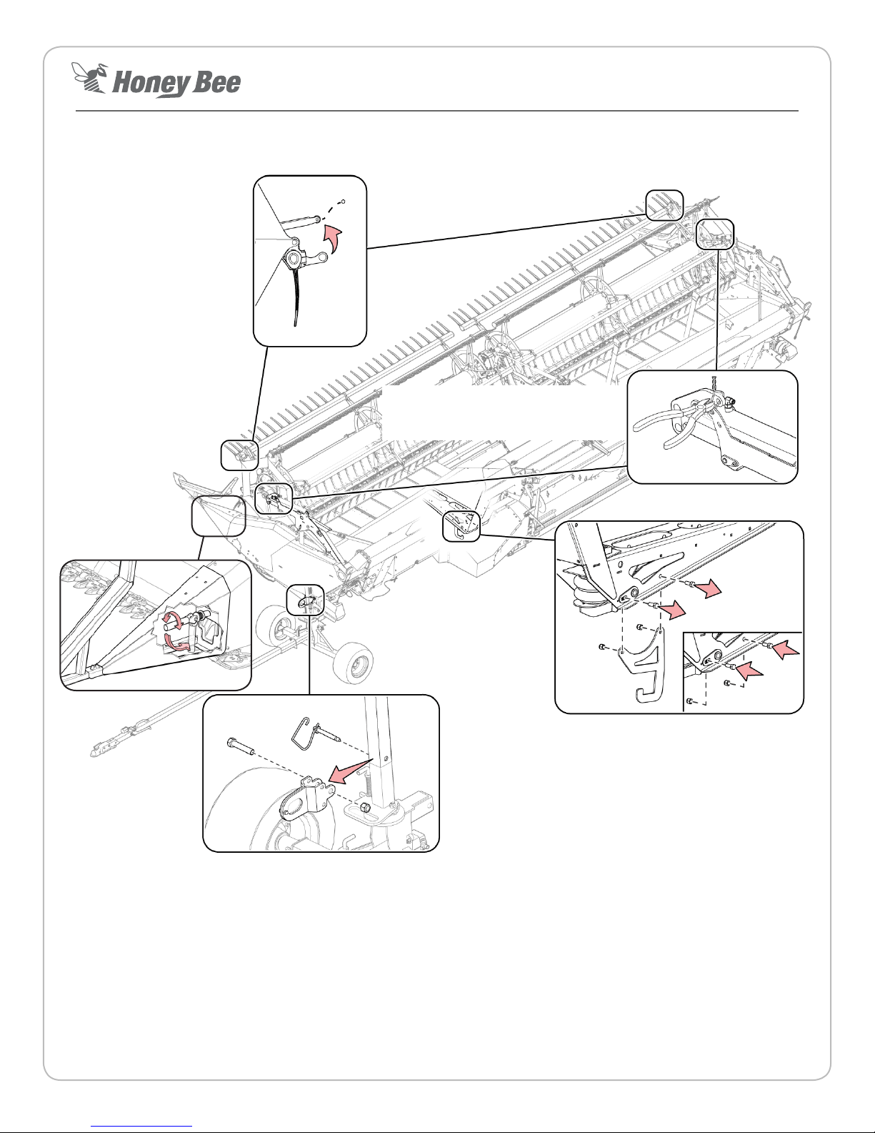
1. Tighten/Loosen the indicated adjuster bolt on the le and
right hand dividers so the dividers are ‘heavy’ enough to
rest at the boom of their travel with the divider extensions
removed. Reinstall the extensions.
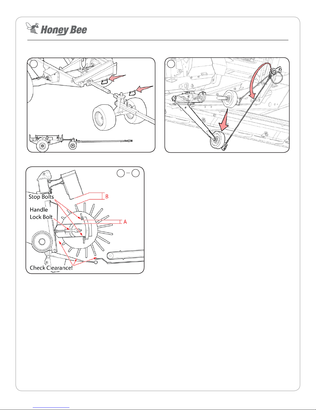
2. Ensure the center sensor(s) are lowered to their eld
posions and dividers are secured and capable of their full
range of moon.
3. Ensure each sensor ‘ag’ contacts its roller at the ‘heel’ of
each strut at the rear of the header.
Roller
Flag
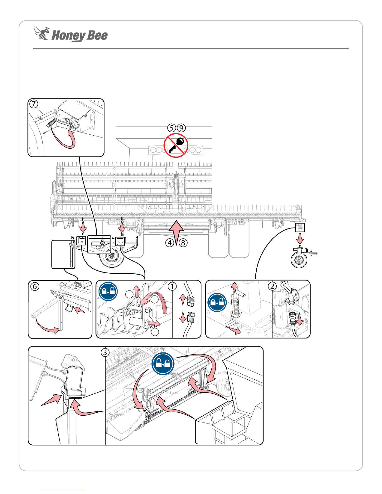
4. Set combine sengs required for header calibraon.
• FLOAT - Set to OFF
• HEADER TYPE - Draper, Rigid, Plaorm (or similar), do
not select Flex type unless specically instructed.
• AUTO HEADER HEIGHT - Set to ON
• AUTO TILT/LATERAL/CONTOUR - Set to ON
5. Park the combine in a ditch with
the header in the air over the road.
Engage the parking brake. (Remain
in this posion through header &
combine calibraon)
6. Select combine make via the
Automax menu (last opon).
7. Set header to FLEX mode prior to calibrang (this calibrates
both RIGID & FLEX modes).
8. Fully extend the hydraulic lt cylinder.
9. Select ‘H/H CALIBRATION’ via Automax main menu.
Follow onscreen instrucons.
The header calibraon is complete when the calibraon done
message appears on the screen with no errors.
Note: Refer to operator manual for detailed instrucons.
IMPORTANT: Don’t make assumpons, don’t skip steps, x all
errors that occur before connuing.
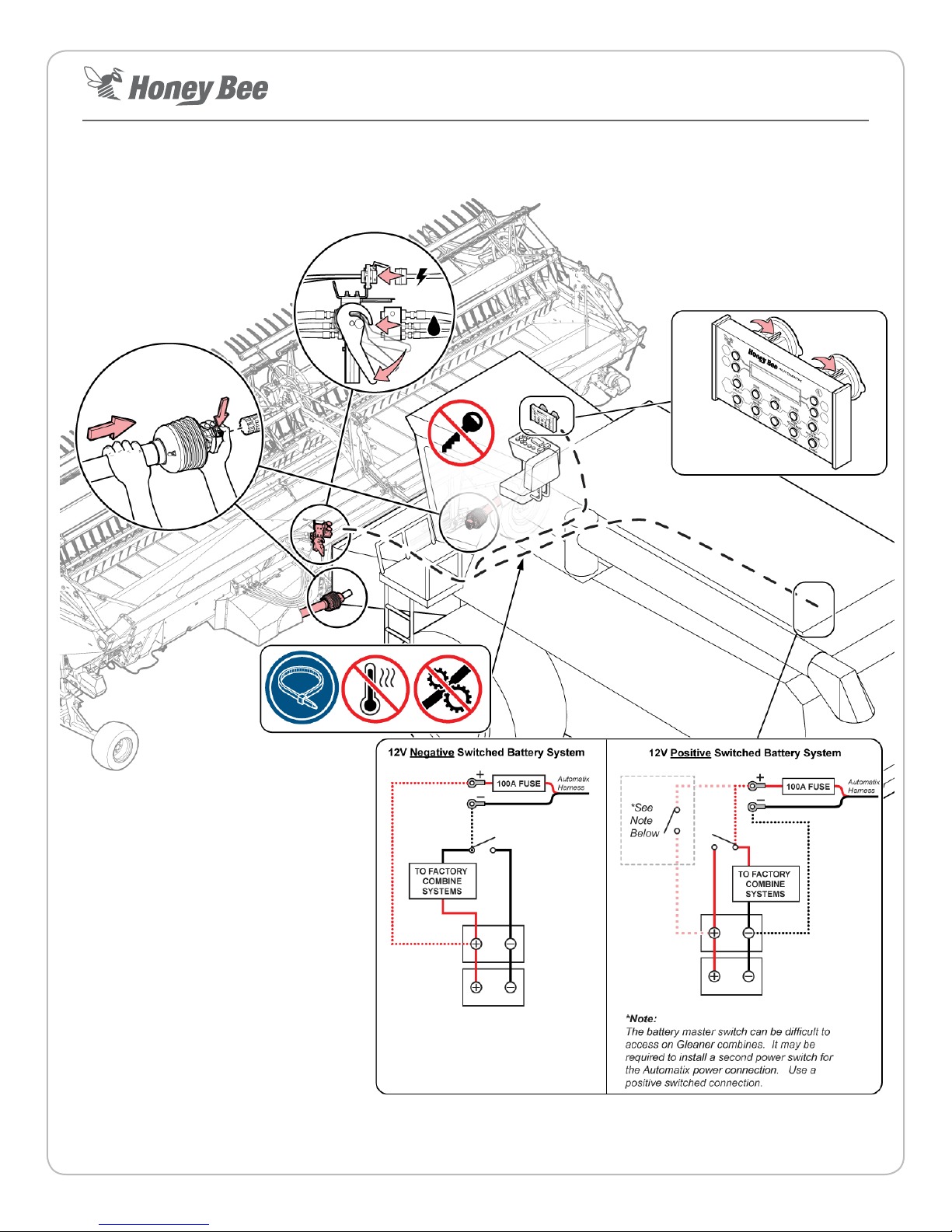
Combine Calibraon
Ensure the combine-specic sengs are entered as described
in the make-specic secons at the end of this document.
1. The combine must be run at maximum RPM (harvest
speed) and the hydraulic oil must be up to operang
temperatures during calibraon.
2. Check the oil level to ensure there is no air in the system
(normally heard as a whining noise).
3. Set the AirFLEX to RIGID mode via the Automax control
panel.
4. Set combine hydraulic header raise rate so it takes 5
seconds to li the header from the lowest posion to the
highest posion.
5. Set combine hydraulic header drop rate so it takes 7
seconds to lower the header from the highest posion to
the lowest posion.
6. Calibrate the combines header height sengs as described
in the combine’s operator manual.
7. Slowly increase header height sensivity via combine
controls unl the header starts hunng up and down.
Decrease sensivity by 10-20% unl the header stops
hunng. Set the lt sensivity to hal the height sensivity
minus 10%, so if the header height sensivity is set to 200,
the lt sensivity should be set to approximately 90 (200/2
= 100, 100 - 10% = 90).
8. When the combine calibraon is done, lower and run
the header and combine rotor so automac header
height is enabled. Record a set-point for header height
on the combine (i.e. 4” (10 cm)). Raise the table all the
way up and laterally lt it all the way to the le or right.
Press the return to set point buon on the combine.
The header should lower back to the set point AND level
out automacally. If this fails, it may indicate a combine
soware problem.
The combine specic sengs listed on the following
pages are recommendaons only. Opmal sengs will
vary by equipment conguraon and condions. It is
the equipment operator’s responsibility to ensure they
operate their equipment in a safe, ecient manner.
The header must be in RIGID mode.for this step!

Page 8 Revision 2.2 P/N: 201827
Honey Bee Manufacturing Ltd.
AirFLEX Header - Quick Start Guide
Set combine feeder house angle.
1. Move the combine away from the slope (as discussed in the
previous secon) and park it on a rm level surface.
2. Start the combine and acvate FLEX mode by pushing the
FLEX buon, then lt the header back by retracng the
hydraulic lt cylinder.
3. Press ‘INFO’ buon unl the header height live view is
displayed.
4. Slowly lower the header unl the cuer bar is pushed all
the way up (no bars showing on live view)
5. Slowly raise the header unl 2 bars are showing on the live
view.
6. Measure the distance from rear of the end paddles to the
ground. Adjust the faceplate angle then remeasure unl
the measurements listed below are achieved.
• If the low prole paddle is installed, it should be
8” from the ground at the indicated locaon (see
illustraon).
• If the high prole paddle is installed, it should be
4” from the ground at the indicated locaon (see
illustraon).
4” (10 cm)
L: ________%
R: ________%
Raise header until 2” (2 bars) show on
FLEX Header Height Live View
8” (20cm)
Low Prole Paddle
High Prole Paddle
Reel Setup
Set the pitch of the reel ngers via the adjuster at the end of
the reel. The middle posion is a good place to start. If crop is
wrapping around the reel, set a less aggressive nger pitch.
Ensure the reel is level and that the reel ngers maintain
a minimum distance of 1-1/2” (3.8cm) from the cuer
bar. Adjust the reel height adjustment bolts located on the
underside of the reel arms if necessary.
Calibraon Troubleshoong:
Access the header height sensor raw voltage view by pressing
the INFO buon. Ensure the sensor output voltage varies by at
least 1.5V through its full range of operaonal moon.
Check that the combine is receiving the correct sensor voltages
from the Automax. Access diagnoscs screen on Combine
display, compare voltage values to the HH Values shown on the
sensor info screen on the automax display. The values should
be similar (usually not idencal).
Verify the correct combine sengs have been entered.
Inspect crop dividers, metal should contact metal if they are
lied and dropped. If the springs are too ght, the dividers
will ride up.
If header is not reacng quick enough, sensivies may
need to be increased. If header is hopping or jumping then
sensivies may need to be decreased.

Page 9 Revision 2.2 P/N: 201827
Honey Bee Manufacturing Ltd.
AirFLEX Header - Quick Start Guide
John Deere Combine Calibraon/Sengs
1. Ensure all opons indicated below by the arrows are
enabled.
2. Enter the width of your header (in feet) and set the stop
height to approximately 80%.
New Holland Combine Calibraon/Sengs
1. Enter the following sengs on the Head 1 screen of the
combine systems. Enter the width of your header in the
Header Width eld and Target Work Width eld.
2. Ensure the following sengs are entered in the Head
2 screen of the combine systems. Use all the values
below as a starng point, adjust as necessary to suit your
condions.

Page 10 Revision 2.2 P/N: 201827
Honey Bee Manufacturing Ltd.
AirFLEX Header - Quick Start Guide
LEXION Combine Calibraon/Sengs
1. Select the front aachment type “Grain cuerbar, make
from other manufacturer”
2. Enter the width of your header minus your intended overlap
(the example below is the value entered for a 45 header
with 1 overlap)
3. Ensure the sengs listed below are entered into the
sensivity screen.
4. Run the learning endstops procedure in the Cross Leveling
secon of the menu.
5. Run the learning endstops procedure in the Front
Aachment Height secon of the menu.
6. Set the feeder house angle for the combine to 0 as
shown below. This value may require further adjustment
depending on your equipment conguraon.
7. Set the Working posion for area calculaon to
approximately 80%.

Page 11 Revision 2.2 P/N: 201827
Honey Bee Manufacturing Ltd.
AirFLEX Header - Quick Start Guide
Massey Ferguson Combine Calibraon/Sengs
NOTE: In order for header height control to funcon on a
Massey Ferguson combine, a ball valve must be installed on
the accumulator and closed.
1. In the combine setup screen:
• Select the “Flex” header type
• Enter the width of your header under “Header Width”
• Set the “Cuto Height” to 80%.
• Ensure the Reel PPR matches he value in the Automax
system (accessible via the automax system menu).
This value should automacally match when the
combine type is selected in the main Automax menu.
2. In the Header Control Table sengs tab:
• Set both Max UP PWM and Max DOWN PWM to 100.
• Set both Max RIGHT PWM and Max LEFT PWM to 80.
3. On the AHHC tab:
• Ensure Automac Header Height Control is enabled
(check mark)
• Set the sensivity to 50% as a starng point.
4. On the Tilt tab:
• Set the Autolt sensivity to 20%
• Set the Autolevel sensivity to 20%
Note: The opmal lateral lt sensivity value is directly related
to the auto header height control sensivity and can be found
using the following equaon:
AHHC Sensitivity
2
- 10%
()
Lateral Tilt Sensitivity =

Page 12 Revision 2.2 P/N: 201827
Honey Bee Manufacturing Ltd.
AirFLEX Header - Quick Start Guide
Gleaner Combine Calibraon/Sengs
Because Gleaner combines are equipped with ‘Bang-Bang’
style control valves, an aermarket modicaon must be
made to the combine so the Automac Header Height Control
system can operate eecvely. There are two opons:
• From AGCO dealer: Pulse Width Modulated
Proportonal Valve Upgrade Kit (Headsight)
• From Honey Bee: BeeBox
If neither of these kits are installed, the Automac Header
Height Control system will not funcon correctly.
Calibraon
Cut height
set point
Header height
sensitivity
Lateral tilt
sensitivity
1. Close the ball valve on the accumulator to disable it
during the calibraiton process. The ball valve can be
parally opened aer calibraon to allow paral ow (up
to 30%). Do not fully open the valve when operang the
AirFLEX.
2. Open the combine sengs screen and enter the following
values:
• Enter the header width in the Header Size eld.
• Set your cut height in the Header Ht Cal eld.
• Set the Width Reduce value to the amount you will
overlap your swaths. If you are running a 40 AirFLEX,
and you want 2 of overlap, then you would enter 5%
(2 is 5% of 40).
3. Start combine and bring engine rpm to just over 2000
RPM.
4. Press hold Cal1 unl lights ash on the combine control
panel.
5. Lower the header all the way to the ground, then press
the Cal 2 buon.
6. Raise the header to highest posion, then press the Cal 2
buon.
7. Tilt header down to the le, then press the Cal 2 buon.
8. Tilt header down to the right, then press the Cal 2 buon.
9. All lights should ash, level the header and press the Cal 1
buon to exit calibraon.
10. If all lights remain o, the combine is calibrated. Refer to
your combine operator’s manual for further details.
11. Set the header height sensivity to the highest possible
seng for opmal performance. Turn up the sensivity
unl the header starts ‘hunng’ up and down, then turn it
down unl the ‘hunng’ stops.
12. The lateral lt sensivity must be set to a lower value
than the Header Height sensivity. The opmal lateral lt
sensivity can be found using the following equaon:
AHHC Sensitivity
2
- 10%
()
Lateral Tilt Sensitivity =

Page 13 Revision 2.2 P/N: 201827
Honey Bee Manufacturing Ltd.
AirFLEX Header - Quick Start Guide
CASE Combine Calibraon/Sengs
1. Enter the following sengs in the Run4 screen in the
combine system. These values are recommendaons and
may be adjusted to suit condions. The lt sensivity
must always remain lower than the height sensivity.
• The header height raise rate and lower rate should be
adjusted so the header takes 7 seconds to lower from
its highest posion to its lowest posion and 5 seconds
to raise from the lowest posion to the highest
posion.
2. Enter the following sengs on the Head 1 screen of the
combine systems. Enter the width of your header in the
Header Width eld and Target Work Width eld.
3. Ensure the following sengs are entered in the Head
2 screen of the combine systems. Use all the values
below as a starng point, adjust as necessary to suit your
condions.
See Note!
Note: If congurating a 700 series or newer combine,
‘Verifeed’ must be selected for the combine type.
Table of contents
Popular Lawn And Garden Equipment manuals by other brands

AquaScape
AquaScape Pond Air 2 Instructions & maintenance

RapidReel
RapidReel Triton GH168-WG Assembly instructions and owner's manual

Gronomics
Gronomics LT 24-72 Assembly instruction

Trolla
Trolla TINE DE-THATCHER Assembly

Texas A/S
Texas A/S PHX2000 user manual

AtriCure
AtriCure AtriClip PRO245 Instructions for use

Gronomics
Gronomics PB 18-48 Assembly instruction

Hyundai
Hyundai HYEA5080 user manual

Craftsman
Craftsman CompuCarve 183.217540 Operator's manual

CORSO ITALIA
CORSO ITALIA WALKWAY installation guide

Hyundai power products
Hyundai power products HYSC1500E instruction manual

Gazebo penguin
Gazebo penguin W1608MR-12 Assembly instructions