Honeywell PERFECT WINDOW ER200 User manual

PRODUCT DATA
Copyright © 1996 Honeywell Inc. • All Rights Reserved
ER200
Perfect Window™
Fresh Air Ventilation System
APPLICATION
The ER200 Fresh Air Ventilation System provides fresh air
while retaining up to 85 percent of the heating or cooling
energy in the exhaust air. It is the energy efficient answer to
controlling indoor air pollution and maintaining comfortable
humidity levels.
FEATURES
•Provides ventilation that helps contractors meet
ASHRAE 62-89.
•Reduces air conditioning load by up to 0.4 ton during
air conditioning season.
•Remote operation provides total control from a single
convenient location.
• Energy transfer wheel for heat and moisture recovery.
•Model available with automatic and economical built-in
preheat frost control for operation at design
temperatures to -29°F (-34°C).
•Rugged steel cabinet.
•No drain required—condensation free.
•Eliminates or reduces need for humidifier.
• Exhausts 80-250 cfm of stale indoor air while bringing
in equal amounts of fresh air.
•Variable fan speed control.
•Latent and sensible energy transfer efficiency up to
85 percent.
•Permanently lubricated fan and wheel bearings.
CONTENTS
Application........................................................................... 1
Features .............................................................................. 1
Specifications ...................................................................... 2
Ordering Information ........................................................... 2
Planning the Installation ...................................................... 4
Installation ........................................................................... 5
Startup and Checkout ......................................................... 10
Operation ............................................................................ 11
Service and Troubleshooting ............................................... 12
Replacement Parts List ....................................................... 15
68-0131-2

ER200 PERFECT WINDOW™FRESH AIR VENTILATION SYSTEM
68-0131—2 2
SPECIFICATIONS
IMPORTANT
The specifications in this publication do not include
normal manufacturing tolerances. Therefore, an
individual unit may not exactly match the listed
specifications. Also, this product is tested and
calibrated under closely controlled conditions and
some minor differences in performance can be
expected if those conditions are changed.
Model:
ER200 Perfect Window™ Fresh Air Ventilation System:
Includes energy transfer wheel, filter, fan and blower
assembly, energy wheel drive motor and speed control. Select
models have frost control preheater, temperature control
module and thermistor assembly.
Color:
White.
Electrical Ratings:
Voltage and Frequency: 120 Vac, 60 Hz or 240 Vac, 60 Hz.
Maximum Current:
Without Frost Control: 2.2A.
With Frost Control: 14.7A at 240 Vac. Neutral required
for motor operation.
Air Flow Capacity:
80 to 250 cfm (40 to 120 L/s).
Efficiency:
75 to 85 percent.
Minimum Outdoor OperatingTemperature:
Without Frost Control (120 Vac): 5°F (-15°C).
With Frost Control (240 Vac): -29°F (-34°C).
Dimensions:
See Fig. 1.
Mounting:
Mounts in conditioned space such as basements, utility
rooms, hallway or closet. Can also be mounted in a
conditioned attic space.
Approvals:
Underwriters Laboratories, Inc. listed.
Canadian Standards Association certified.
Home Ventilating Institute certified.
Weight:
Unit Weight: 74 lb (34 kg).
Shipping Weight: 98 lb (44 kg).
Accessories:
272672 Seven-inch Round Balancing Grid.
272673 Seven-inch Weather Cap.
H8808C Dehumidistat.
ORDERING INFORMATION
When purchasing replacement and modernization products from your authorized distributor, refer to the TRADELINE® Catalog
or price sheets for complete ordering number.
If you have additional questions, need further information, or would like to comment on our products or services, please write or
phone:
1. Your local Honeywell Home and Building Control Sales Office (check white pages of your phone directory).
2. Home and Building Control Customer Relations
Honeywell, 1885 Douglas Drive North
Minneapolis, Minnesota 55422-4386
In Canada—Honeywell Limited/Honeywell Limitée, 35 Dynamic Drive, Scarborough, Ontario M1V 4Z9. International Sales and
Service Offices in all principal cities of the world. Manufacturing in Australia, Canada, Finland, France, Germany, Japan, Mexico,
Netherlands, Spain, Taiwan, United Kingdom, U.S.A.

ER200 PERFECT WINDOW™FRESH AIR VENTILATION SYSTEM
68-0131—2
3
M6125
KNOCKOUTS
FOR LINE CORD
OR HARDWIRED
POWER SUPPLY
LOW VOLTAGE
TERMINAL
ACCESS COVER
7 (178) DIAMETER DUCT COLLARS
ALLOW
11-1/2 (292)
MINIMUM
FOR FILTER ACCESS
38
(965)
32
(813)
22
(559)
3
(76)
2-1/4
(57) 3-1/2
(89)
23-1/4
(591)
5/8
(18)
8-1/4
(210) 1/8
(3)
4-1/4
(119)
13-1/8
(333)
10-7/16
(265)
8-15/16
(226)
5-13/16
(147)
6-9/16
(166)
Fig. 1. ER200 installation dimensions in in. (mm).

ER200 PERFECT WINDOW™FRESH AIR VENTILATION SYSTEM
68-0131—2 4
PLANNING THE INSTALLATION
Application
The Fresh Air Ventilation System is designed to provide stale
air exhaust and fresh air supply. The system draws outdoor
fresh air through the ventilator for distribution throughout the
house. Stale air is exhausted through the ventilator and to the
outdoors. Ducting between the ventilator and outdoors and
ducting in unconditioned space must be insulated. See Fig. 2.
Mounting Position and Location
The ER200 can be suspended from the exposed floor/ceiling
joists, ceiling or floor surface, closet floor or utility room to
accommodate ducting between joists. The ER200 may be
mounted in any position. Locate the fresh air intake 6 ft (2m)
or farther from the stale air exhaust to avoid exhaust air
reentry. See Fig. 2.
NOTE: Build an insulated frame around the ventilator when
installing in an unconditioned space.
Frost Control Guidelines
ER200 120 Vac models are recommended for use to an
outdoor design temperature of 5°F (-15°C). In colder climates,
use the 240 Vac model that includes a preheat frost control
system to avoid frost formation in the ventilator.
NOTE: For pool, spa and other high humidity applications, a
frost control model is recommended for operation at
outdoor design temperatures below 15°F (-9°C).
Ducting
Ducting between the Fresh Air Ventilation System and the
outdoors must be insulated and have a continuous air vapor
barrier. See Fig. 3. Fresh air supply ducts from the Fresh Air
Ventilation System to the room must be insulated only when
located in an unconditioned space (without heating or
cooling).
WEATHER CAP
(ACCESSORY)
FRESH AIR SUPPLY
(INSULATE DUCTING
IN UNCONDITIONED
SPACE ONLY)
REMOTE DEHUMIDISTAT (OPTIONAL)
REMOTE FRESH AIR CONTROL
STALE AIR EXHAUST
(INSULATE DUCTING)
STALE AIR RETURN
(INSULATING DUCTING
IN UNCONDITIONED
SPACE ONLY)
WEATHER CAP
(ACCESSORY)
FRESH AIR INTAKE
(INSULATE DUCTING)
M6122B
Fresh Air Ventilation System
Système de ventilation à air frais
Fig. 2. Typical system components for ER200.
INSULATED
FLEX DUCT COLLAR ON
VENTILATOR
SEAL INTERIOR LINING
OF FLEX DUCT TO
INSIDE COLLAR
SEAL OUTER LINING
OF FLEX DUCT TO
OUTER COLLAR
M6123
Fig. 3. Sealing insulated duct terminations.
CAUTION
All ducting to the outdoors must be installed above
anticipated snow lines and fitted with a weather cap
that incorporates bird screening.
Design and installation of ductwork must be in accordance
with standard HVAC practice to deliver required quantities of
fresh air to the temperature controlled space and exhaust
equivalent quantities of room air to the outside.
Make intake and exhaust duct runs as short as possible with
few bends or elbows.
1. Choose duct sizes that will maintain 0.2 in. wc static
pressure.

ER200 PERFECT WINDOW™FRESH AIR VENTILATION SYSTEM
68-0131—2
5
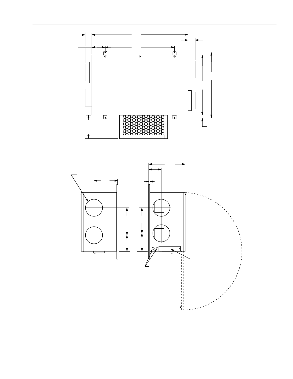
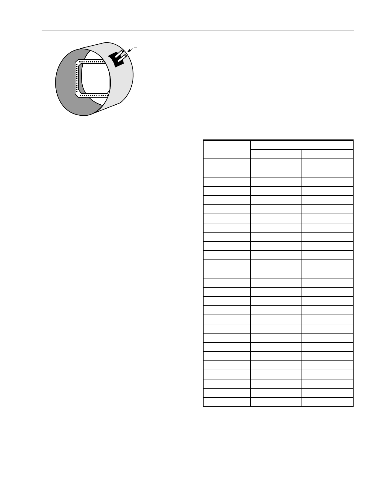
2. Use 7-in. diameter round duct for all connections to and
from the ventilator.
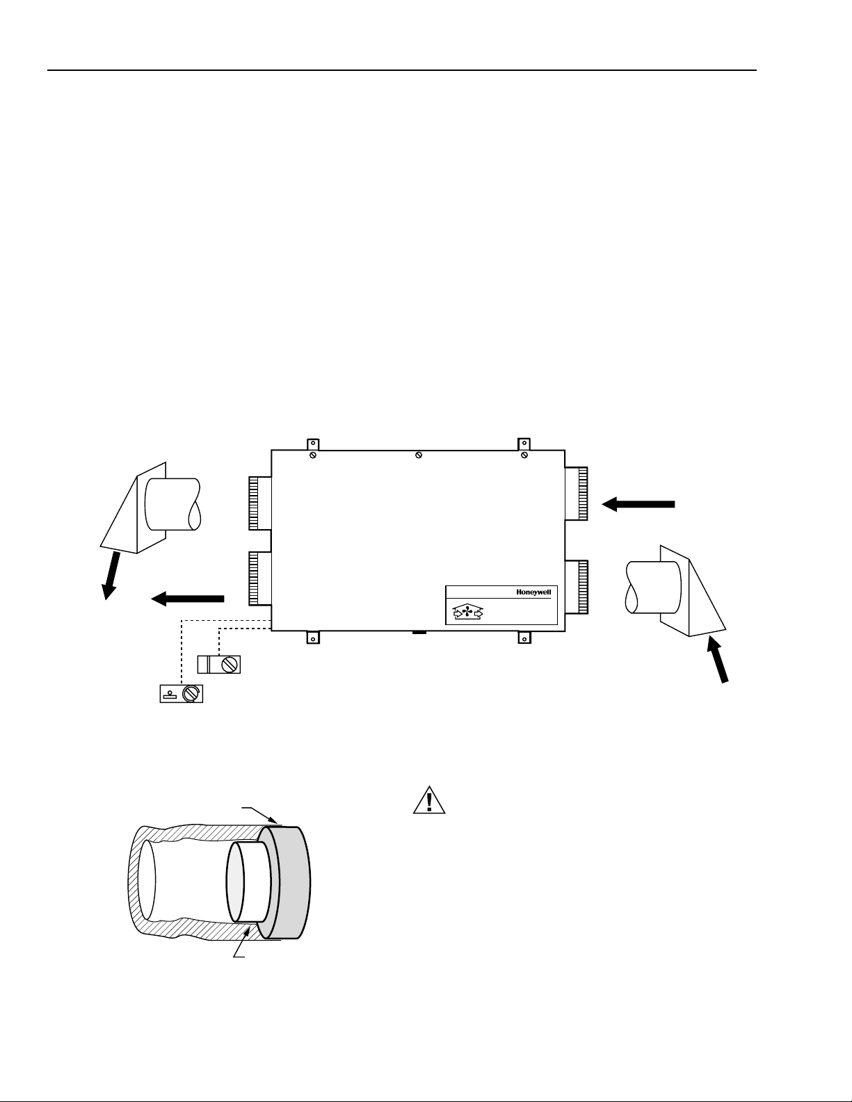
3. Plan fresh air supply for good ventilation efficiency.
Separate outside vents from intake and exhaust by at
least 6 ft (2m).
NOTE:
•Fresh air should not blow directly onto
occupants or thermostat.
•Do not locate the fresh air intake close to
known sources of pollutants such as
automobile exhaust, dryer vent or chimney
smoke.
4. Supply air can be ducted directly to the return side of a
forced-air heating or air conditioning system. This can
provide excellent distribution of fresh air while saving
substantially on installation.
NOTE: Continuous operation of the ER200 during
periods of occupancy is recommended. When
the furnace air handler operates, fresh air will
be distributed through the heating/air
conditioning supply registers. When the air
handler is off, fresh air will be delivered
through both supplies and returns.
5. Use electrical interlock or automatic powered damper to
prevent unwanted entry of outside air in the event that
the ER200 is turned off while the furnace air handler
continues to operate.
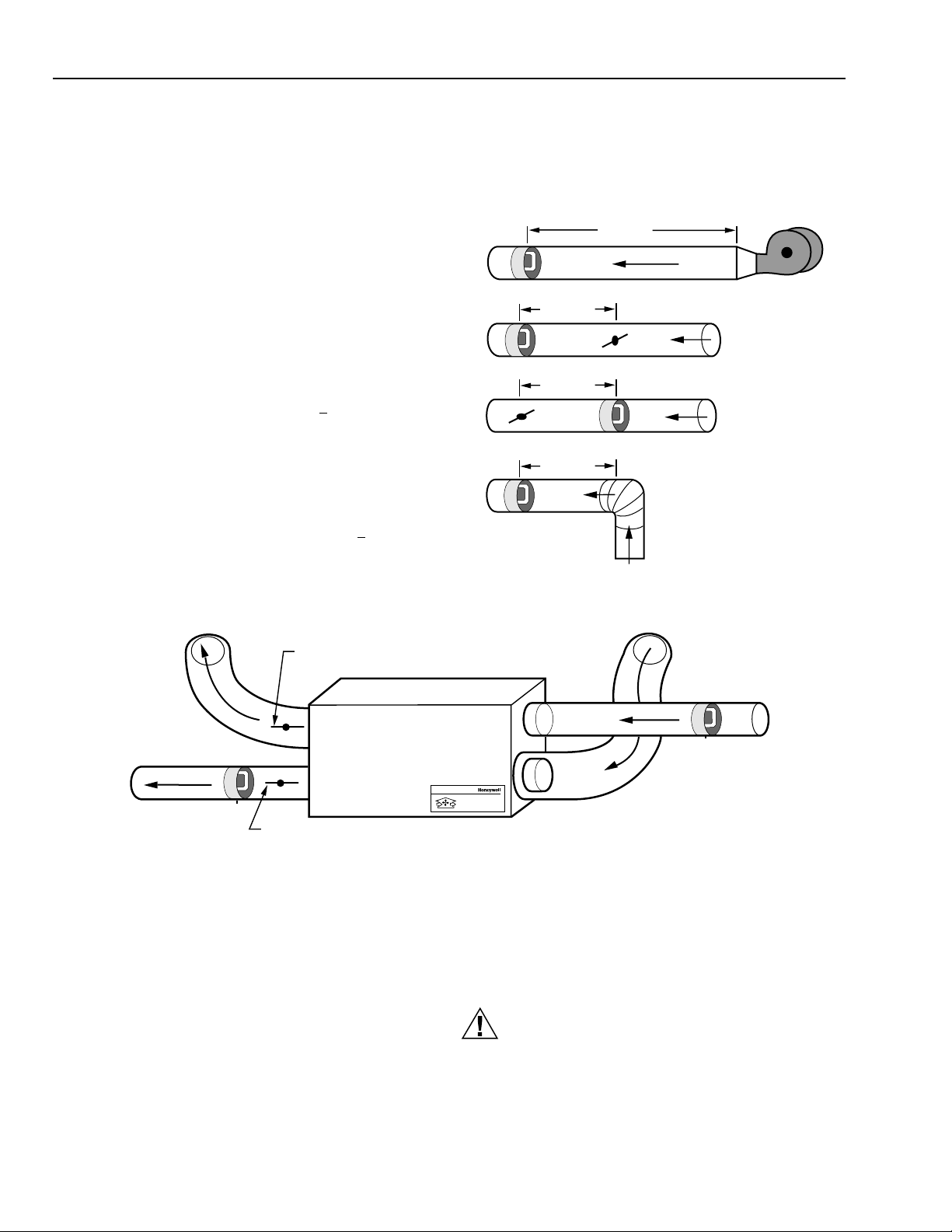
Balancing Airflow
Balancing the airflow is important to verify that the Fresh Air
Ventilation System is delivering the intended airflow and
energy performance. Use the Balancing Airflow instructions in
the Installation section to check and balance the airflow.
Controls
Remote Override Switch Functions—On/Off Control
If continuous ventilation is not required, an on/off control can
be used to activate the ventilator when it is switched to
Standby. Controls that can be used for this function include
dehumidistats, timers, wall switches and the ventilate function
of the Perfect Climate® Comfort Center™. If moisture control
in bathrooms is a primary function of the system, a
dehumidistat can be used to switch the ventilator from a Low
or Standby setting to the High setting. Moisture removal
throughout the entire home can be achieved only when the
outside air contains less moisture than the inside air (typically
during cold weather conditions).
With the Perfect Climate® Comfort Center™, the ventilator
can be controlled automatically by using the programmed
times or manually by pressing the VENTILATE button on the
keypad. See the Perfect Climate Comfort Center User’s Guide
(form 69-0891) for complete instructions.
Moisture Control
For optimum indoor air pollutant reduction and humidity
control, continuous operation of the ventilation system is
recommended. Increased moisture removal will always occur
at maximum ventilation rates. This high setting should be
used when first occupying a new building to remove excess
moisture from new wood, plaster, cement and other moisture
absorbing construction materials. If the system is wired to a
dehumidistat, preselected moisture levels will be maintained
automatically. For correction of severe moisture problems, the
sensible energy transfer wheel can be substituted for the
desiccant coated wheel.
Frost Control
Select models have a factory installed automatic preheat frost
control system that operates to prevent the inlet air
temperature from falling below 10°F (-12°C). The frost control
system is designed to maintain this level down to outdoor
temperatures of -29°F (-34°C) with 40 percent indoor relative
humidity. The light located next to the press-to-test button
lights when the frost control preheater is active or the TEST
button is pressed.
IMPORTANT
Release the TEST button as soon as the neon light
comes on. Pressing the TEST button longer can
cause overheating of the ventilator.
INSTALLATION
When Installing this Product
1. Read these instructions carefully. Failure to follow them
could damage the ER200 or cause a hazardous
condition.
2. Check the ratings given in the instructions and on the
ER200 to make sure the product is suitable for your
application.
3. Installer must be a trained, experienced service
technician.
4. After installation is complete, check out product
operation as provided in these instructions.
CAUTION
Disconnect power supply before wiring to prevent
electrical shock or equipment damage.
Unpack Fresh Air Ventilation System
The Fresh Air Ventilation System is shipped assembled. Check
that all the components are included. The unit consists of:
•Painted finish cabinet with starting collars.
•Variable speed fresh air control.
•Built-in preheater (on selected models).
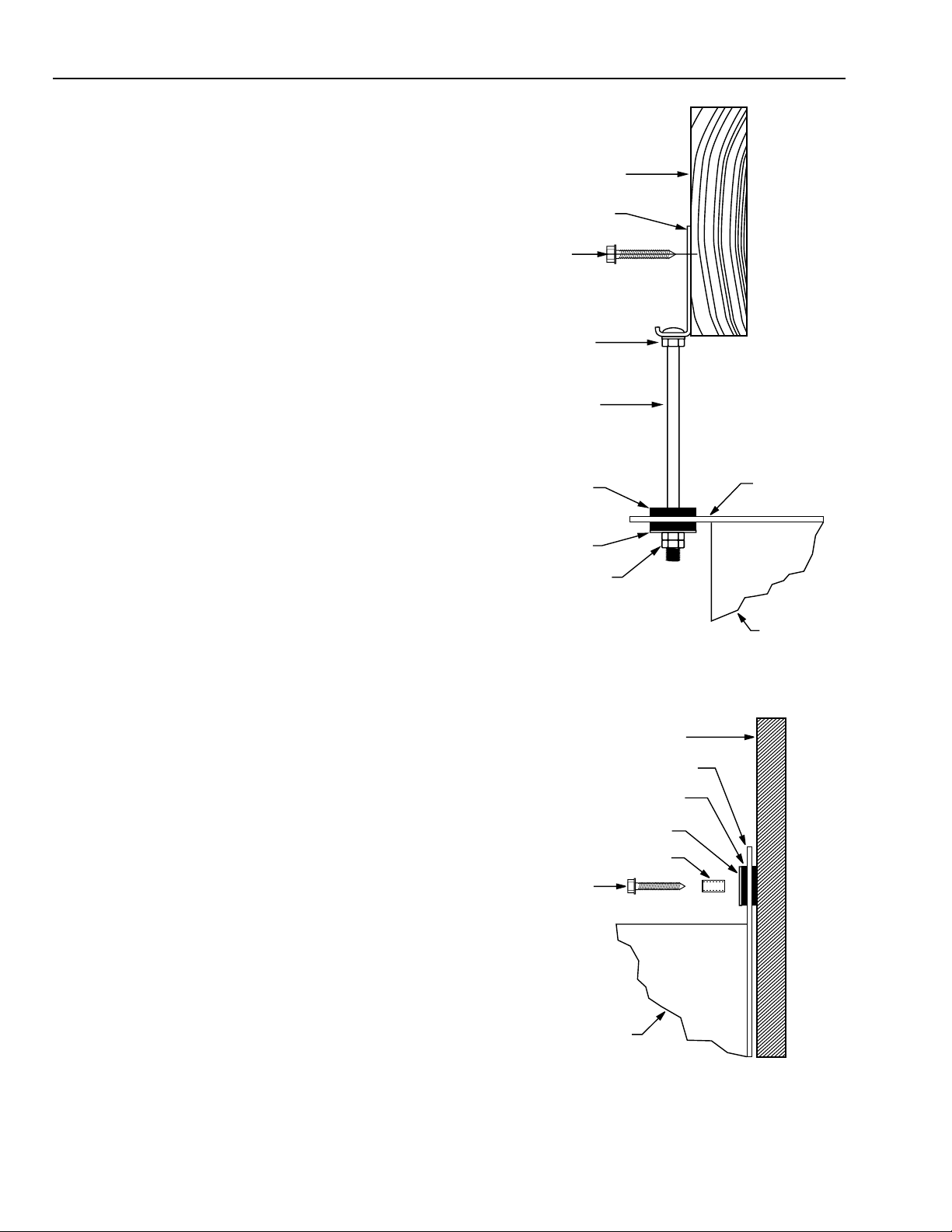
•Two mounting straps.
•Hardware package.
•Literature package.
The Fresh Air Ventilation System comes ready for installation
as received. Wiring and ducting are required to complete the
installation. Before proceeding, check to make sure all the
components are available.
Review the Installation Plan
Place the unit on the floor; position it as it will be when
installed. Cut out the mounting template printed on the outer
carton. Use the template to determine the location of the
mounting straps. Make sure all the required duct work and
additional accessories are available before starting the
installation.

ER200 PERFECT WINDOW™FRESH AIR VENTILATION SYSTEM
68-0131—2 6
Suspended Mounting
쐃Attach two mounting straps to the bottom of the Fresh
Air Ventilation System cabinet. Use four of the no. 10-24
x 1/2 in. round head machine screws and four no. 10
internal tooth washers supplied in the hardware
package.
쐇Attach a pair of hanging brackets to a joist. See Fig. 4.
Space the brackets 25-1/4 in. apart on centers. Use two
1-1/2 in. lag screws to secure each bracket.
쐋Locate and attach the remaining pair of brackets on a
joist so each pair is 32 in. apart and perpendicular to
each other.
쐏Install a lock washer and a hex nut onto each of the four
6 in. bolts. Thread each hex nut to 1/2 in. below the bolt
head.
쐄Insert the bolts through the mounting strap bushing and
secure each bolt with a pair of hex nuts. See Fig. 4.
쐂Raise the cabinet to slip the heads of the bolts over the
edges of the brackets and allow the bolt shanks to
engage the slots in the brackets. Tighten the
lockwasher and hex nut upward against the bottom of
each bracket. The cabinet is now positioned for
attachment of ducting.
Wall Mounting
쐃Attach two mounting straps to the bottom of the cabinet.
Use four each of the no. 10-24 x 1/2 in. round head
machine screws and no. 10 internal tooth washers as
supplied in the hardware package.
쐇Insert a steel sleeve into each of the four mounting
strap bushings. See Fig. 5. With the cabinet mounted
horizontally, these bushings will be spaced 32 in. on
centers for direct attachment to wall studs spaced 16 in.
on centers. For other wall configurations, using of a
mounting board may be required.
쐋Support the cabinet at the desired location and secure
with four no. 12 x 1-1/2 in. lag screws. The Fresh Air
Ventilation System is now mounted and ready for
attaching the ducting.
Wiring
Before wiring 240 Vac models, disconnect power supply to
prevent electrical shock or equipment damage. All wiring must
comply with local codes and ordinances.
120 Vac models are equipped with a line cord and a standard
3-prong plug that plugs into a wall outlet. See Fig. 6. 240 Vac
models, with frost control, require 240 Vac for the heater and
must be hardwired per the local electrical code. A neutral
must be connected to provide 120 Vac to the motors.
The Fresh Air Control is connected to the ventilator by six low
voltage wires.Wiring is one to one, two to two, etc., see Fig. 7.
Ter minal 2 on the Fresh Air Control is used as a tie point for
the optional remote switches; no factory wiring is connected
to this terminal.
FLOOR JOIST IN
BASEMENT CEILING
HANGING
BRACKET
HEX NUT
AND LOCKWASHER
1/4 20x6 BOLT
VIBRATION
DAMPENING BUSHING
WASHER
HEX NUTS (2)
MOUNTING
STRAP
CABINET
1-1/2 LAG SCREW (2)
M6127
Fig. 4.Typical mounting when suspending unit from
basement ceiling with four suspension bolts (one shown).
VIBRATION DAMPENING BUSHING
WASHER
UNIT MOUNTING STRAP
CABINET
1-1/2 LAG SCREW (2)
STEEL SLEEVE
MOUNTING SURFACE
M6128
Fig. 5. Typical mounting when unit is mounted to a wall
with four lag screws (one shown).

ER200 PERFECT WINDOW™FRESH AIR VENTILATION SYSTEM
68-0131—2
7
FRESH AIR
CONTROL
PC8900,
DEHIMIDISTAT,
OR OTHER
OPTIONAL
REMOTE
SWITCHES
CAPACITOR
BLOWER
LO
123456
1
23
4
5
6
1
2
34
MAIN
POWER
SWITCH
M5301B
MASTER
CONTROL
MODULE
VIOLET
CONNECTOR
"A"
ON
OFF
WHITE
RED
BLACK
7
5
38 1
264
1
2
3
WHEEL
DRIVE
MOTOR
2.0 MFD (1.2 MFD)
CAPACITOR
GREEN
CONNECTOR
"F"
WHITE (BLUE) COIL 2
BLACK (BLUE) COIL 1
BLACK
(RED)
COIL 2
WHITE
(BLACK)
COIL 1
BLUE
BLUE
CONNECTOR
"B"
WHITE
HI
WHITE
BLACK
GREEN
LINE CORD
AND PLUG
FOR 120 VAC
(ALTERNATE
CONSTRUCTION)
RED
1
1
ADDITIONAL CONTACTS (I.E., TIMERS, WALL SWITCHES)
WIRED IN PARALLEL TO TERMINALS ONE AND TWO WILL
SWITCH THE VENTILATOR TO HIGH SPEED.
Fig. 6. Wiring ER200 without preheater, with line cord and plug.

ER200 PERFECT WINDOW™FRESH AIR VENTILATION SYSTEM
68-0131—2 8
TEST
LAMP
TEST
SW
BLACK
GREEN
CONNECTOR
"C"
WHITE
RED
BLUE
FRESH AIR
CONTROL
PC8900,
DEHUMIDISTAT,
OR OTHER
OPTIONAL
REMOTE
SWITCHES
CAPACITOR
BLOWER
LO
1234
56
BLACK
BLACK
BLACK
BLACK
BLACK
BLACK
1
23
4
5
6
1
2
34
MAIN
POWER
SWITCH
M5298B
MASTER
CONTROL
MODULE
VIOLET
CONNECTOR
"A"
ON
OFF
CONNECTOR "E"
PREHEATER ASSEMBLY
3000 WATT - 240 VAC
TEMPERATURE
CONTROL
MODULE
FIELD
ADJUST
SHAFT
CONNECTOR
"D"
1
2
3
THERMISTOR ASSEMBLY
WHITE
RED
BLUE
BLACK
WHITE
7
5
38 1
26
4
1
2
3
CONNECTOR
"F"
WHITE
RED
BLACK
GREEN GROUND
L2, 240 VAC
L1, 240 VAC
NEUTRAL
BLUE
BLUE CONNECTOR
"B"
WHITE
HI
12
34
5
6
1
2
3
WHEEL
DRIVE
MOTOR
2.0 MFD (1.2 MFD)
CAPACITOR
GREEN
WHITE (BLUE) COIL 2
BLACK (BLUE) COIL 1
BLACK
(RED)
COIL 2
WHITE
(BLACK)
COIL 1
(ALTERNATE
CONSTRUCTION)
RED
1
1ADDITIONAL CONTACTS (I.E., TIMERS, WALL SWITCHES)
WIRED IN PARALLEL TO TERMINALS ONE AND TWO WILL
SWITCH THE VENTILATOR TO HIGH SPEED.
Fig. 7. Wiring ER200 with preheater.

ER200 PERFECT WINDOW™FRESH AIR VENTILATION SYSTEM
68-0131—2
9
PRESSURE TAPS;
CONNECT TO
MAGNEHELIC GAUGE
OR INCLINE
MANOMETER
M3101
Fig. 8. Airflow measurement grid.
Balancing Airflows
Balancing system airflow is important to verify the Fresh Air
Ventilation System is delivering the intended airflow.
Balancing is a good check for duct system blockages, fan
operation, and that system exhaust and supply pressure are
equal.
Honeywell 272672 Round Balancing Grid can be mounted in
the duct work connected to the Fresh Air Ventilation System
to balance the airflow. See Fig. 8. Grids can be used
temporarily or installed permanently to allow periodic check.
The grid is connected to a pressure measurement to translate
the pressure reading into an airflow reading (cfm or L/s) using
the table mounted on the grid or Table 1.
The grids must be used with a pressure measurement device
capable of measuring pressures ranging from 0 to 0.25 in. wc
(60 Pa). Use a magnehelic gauge or incline manometer,
available from your local wholesaler. A single pressure
measurement device can be used to measure airflow in both
Fresh Air Ventilation System air streams.
Measuring and Balancing Fresh Air Ventilation
System Airflows
One or two grids can be installed to take the measurements.
When using one, move it from the exhaust to the supply air
ducts to get the readings. Use the following procedure to get
accurate measurements:
쐃Close all doors, windows and any other openings in the
building. Exhaust appliances (exhaust fans, furnace,
clothes dryer, water heater, etc.) must be off while
measuring airflow and balancing the Fresh Air
Ventilation System.
쐇Insert the grid in the exhaust duct. Install so that the
arrow on the grid casing points in the direction of the
airflow in the duct work. Mount on the warm side of the
duct work where airflow turbulence from a fan blower,
duct elbow or damper is minimized. Turbulence can
result in incorrect airflow measurements. See Fig. 9.
NOTE: The magnehelic gauge or incline manometer
must be mounted on a level surface. Incline
manometers include a bubble-type level
indicator. When the unit is level, zero the
pressure measuring device. Magnehelic
gauges must be lightly tapped to verify
pressure reading before making any
adjustments or readings.
쐋Attach flexible tubing from the low pressure port on the
pressure gauge to the downwind tap on the airflow grid.
쐏Seal the ductwork using duct tape.
쐄Attach tubing from the high pressure tap on the
pressure measuring device to the upwind tap on the
airflow grid.
쐂Turn on airflow and note the pressure registering on the
pressure measurement gauge. If the reading on the
pressure measuring device is negative, the pressure
connections are reversed and need to be changed.
쐆Use the table on the airflow grid or Table 1 below to
translate the pressure measurement into an airflow
reading.
Table 1. Pressure To Airflow Conversion Chart For a
Seven-inch Airflow Grid.
Pressure Airflow
(in. wc) cfm L/s
0.010 73 (34)
0.015 89 (42)
0.020 103 (48)
0.025 115 (54)
0.030 126 (59)
0.035 136 (64)
0.040 145 (68)
0.045 154 (73)
0.050 162 (76)
0.055 170 (80)
0.060 178 (84)
0.065 185 (87)
0.070 192 (90)
0.075 199 (94)
0.080 205 (97)
0.085 211 (100)
0.090 218 (103)
0.095 223 (105)
0.100 229 (108)
0.105 235 (111)
0.110 240 (113)
0.115 246 (116)
0.120 251 (118)
0.125 256 (121)
0.130 261 (123)
0.135 266 (126)
0.140 272 (128)
NOTE: Check local codes for balancing requirements.
Normally the Fresh Air Ventilation System is
balanced at its highest speed; however, some
local codes require that the Fresh Air
Ventilation System be balanced at its normal
continuous speed.

ER200 PERFECT WINDOW™FRESH AIR VENTILATION SYSTEM
68-0131—2 10
쐊When the supply air from the Fresh Air Ventilation
System is connected to the furnace return:
• Balance with the furnace blower
on
if the furnace
fan normally runs continuously.
•Balance with the furnace blower
off
if the furnace
fan runs only when the heating or cooling is on.
쐎Turn on the Fresh Air Ventilation System. Wait 60 seconds
for airflows to stabilize. Record reading in the exhaust
air stream.
NOTE: If using a magnehelic gauge, tap lightly before
recording the reading.
쐅Move the grid to the supply air stream and repeat steps
3 through 9.
쐈To correct imbalance:
•Airflow is greater in supply air section of Fresh Air
Ventilation System—install a damper on the
downwind side of the ventilator (warm side) and
adjust until the airflow is within +10 percent of the
exhaust airflow. See Fig. 10.
—When radon control is a concern, balance
the supply airflow to provide 10 to15 cfm (5 to
8 L/s) more airflow than the exhaust.
•
Airflow is greater in exhaust section of Fresh Air
Ventilation System
—install a damper on the
downwind side of the exhaust blower (cold side)
and adjust until the airflows are within +10 percent.
See Fig. 10.
—When radon control is a concern, balance so
that exhaust is 10 to 15 cfm (5 to 8 L/s) less
than supply airflow.
After the damper is adjusted and set, cover the damper with
insulated ducting and tape.
쐉Mark the damper position on the duct for future
reference.
씈Place a sticker on the unit and record airflows
measured while balancing, name of installer and date
for future reference.
Fig. 9. Location of airflow grid in in. (mm).
30 IN (750)
12 IN (300)
12 IN (300)
12 IN (300)
M3102
STALE
AIR FROM
HOUSE
AIRFLOW GRID
INSTALL DAMPER DOWNWIND OF EXHAUST BLOWER IF AIRFLOW IS
GREATEST IN EXHAUST AIR. ADJUST TO EQUAL SUPPLY AIRFLOW.
INSTALL DAMPER DOWNWIND OF SUPPLY BLOWER IF AIRFLOW IS
GREATEST IN SUPPLY AIR. ADJUST TO EQUAL EXHAUST AIRFLOW.
FRESH AIR TO HOUSE
AIRFLOW GRID
M3109D
STALE AIR
EXHAUST
FRESH AIR
INTAKE
Fresh Air Ventilation System
Système de ventilation à air frais
Fig. 10. ER200 balancing airflow.
STARTUP AND CHECKOUT
After the installation and wiring are complete, make a final
check that all components are working.
쐃Open the cabinet door.
쐇Turn the master switch on the side of the cabinet to the
ON position.
쐋Turn on fresh air control to verify airflow and wheel
rotation. Operate the control from MAX to MIN to verify
decrease in airflow.
쐏Activate any line voltage override switch to verify
function. Master power switch must be on.
쐄For the model equipped with preheat frost control,
check out operation of the frost control system by
momentarily depressing the press-to-test button located
on the top blower plate using a pen or small
screwdriver. The neon lamp adjacent to the test button
lights to indicate preheater operation.
CAUTION
Press button momentarily to avoid overheating unit.
Do not hold down button for more than two seconds.
Fresh air filter must be in place. Do not touch heater
element.

ER200 PERFECT WINDOW™FRESH AIR VENTILATION SYSTEM
68-0131—2
11
쐂The ON/OFF illuminated rocker switch located on the
side of the cabinet should be on at all times except
when providing routine maintenance or servicing the
unit.
쐆A fresh air control located at a remote location turns the
unit on and off and allows continuously variable
selection of ventilation rates. Airflow rate is determined
by the specific application, the number of occupants
and the design of the ductwork system. Gradually
adjust the airflow rate until the desired comfort level is
attained.
Setting Frost Control Temperatures
CAUTION
Only an authorized appliance repair or service
technician should make adjustments to the frost
control preheat temperature.
The preheat temperature is factory set to an inlet air
temperature of 10°F (-12°C). This setting protects the
desiccant coated energy transfer wheel from freezing at
indoor relative humidities of up to 40 percent.This setpoint
can be changed by rotating the slotted potentiometer
extension arm. The arm is accessible at the end of the
temperature control module attached to the underside of the
fresh air blower cover. (See Fig. 11.)
For high indoor humidity conditions such as pool or spa
applications and outdoor temperatures at or below 10°F (-12°C),
the preheat setpoint can be adjusted to maintain up to 15°F
(-9°C) inlet air temperature (suitable for 50 percent indoor
RH). This is accomplished by rotating the potentiometer
extension arm clockwise to the stop mark at 50 percent, 15°F.
Many buildings require humidifiers to maintain comfortable
indoor relative humidities at approximately 30 percent, and
many operate throughout the winter season at 20 percent or
lower. In these situations, greater energy savings can be
attained with lower preheat temperatures. To accomplish this,
rotate the field adjustment potentiometer counterclockwise to
the stop.
This will establish a 0°F (-18°C) temperature set point, which
is acceptable when maximum indoor relative humidity will be
20 percent or less.
M8041
TEMPERATURE
CONTROL
MODULE
FORADJUSTMENT,SEE
INSTRUCTIONMANUAL
POURAJUSTER, VOIR LE
MANUELD'INSTRUCTION
20%
50%
POTENTIOMETER
EXTENSION ARM
Fig. 11. Temperature control module adjustment.
OPERATION
The Fresh Air Ventilation System has an energy transfer
wheel that rotates between two counter-flowing air streams
(supply and exhaust). The wheel picks up heat from one side
and gives it to the other (cooler) air stream.This causes a
temperature gradient through the wheel from the warm side to
the cool side.

ER200 PERFECT WINDOW™FRESH AIR VENTILATION SYSTEM
68-0131—2 12
As the cooler air stream passes through the porous wheel, it
picks up heat from an increasingly warmer surface. The
rotation takes that same surface into the opposing air stream
where the warmer air gradually gives up heat to the
increasingly cooler surface of the film. The rotation is
constantly regenerating the temperature gradient for
maximum efficiency.
The desiccant energy recovery wheel also removes moisture
during the rotation. In summer, the wheel strips moisture from
the incoming warm humid air stream. The moisture is then
transferred into the cooler, dryer exhaust air. In winter,
moisture in the exhaust air stream is transferred to the
incoming dry fresh air stream. This eliminates the need for a
condensation drain or pan.
SERVICE AND TROUBLESHOOTING
Service
Frost Control System
Test the frost control system by pressing the test button
annually before the heating season starts.
CAUTION
Press the test button only momentarily—do not hold
down more than two seconds. Longer testing can melt
the fusible link in the over-temperature safety circuit. If
this occurs, it will be necessary to replace the heater
assembly.
Fresh Air Filter
Replace the fresh air filter at least twice a year. To remove
the filter:
쐃Unscrew the access panel thumbscrews to remove the
filter access panel.
쐇Slide the fresh air filter out of the Fresh Air Ventilation
System.
쐋Check the filter and replace if clogged.
쐏Replace the filter access panel on the Fresh Air
Ventilation System and tighten the thumbscrews.
Weather Caps
Check to ensure that the fresh air inlet and exhaust grilles do
not become clogged with debris like grass, leaves or snow.
Energy Transfer Wheel
Check the energy transfer wheel for build-up of dirt and
debris.
NOTE: Energy transfer is not affected by stained surfaces.
Remove and Clean the Energy Transfer Wheel
쐃Unscrew the screws holding the ventilator door and
open the door.
쐇Take out the center divider.
쐋Remove the belt from the rim of the wheel.
쐏Unscrew the screw in the center of the hub.
쐄Use the rim of the wheel and lift the wheel straight off
the drive shaft.
쐂Spray the energy transfer wheel thoroughly with
household spray cleaner (Fantastik® or equivalent).
Rinse with warm water. Use a soft brush to remove
stains between the plastic windings. Shake excess
water from the wheel.
쐆Replace the wheel on the drive shaft.
쐊Replace and tighten the screw in the center of the hub.
쐎Place the belt back on the wheel.
쐅Reinstall the center divider.
쐈Close the ventilator door and tighten the screws.
Belt Drive
If the blower is operating (air coming out of fresh air vent) but
energy transfer wheel does not rotate, check the pulley
system. Replace broken or stretched belts.
If the blower fails to operate with the master switch in the ON
position and the Fresh Air Control on, check circuit breakers
in house electrical panel. If power is supplied to the unit but
the blower does not operate, contact your local HVAC
contractor.
Troubleshooting
All required maintenance and repair can be accomplished by
HVAC service personnel or appliance repair persons.
Use Fig. 12 and 13 to identify the problems and causes. Start
at Level 1 in Fig. 12 and proceed vertically downward through
each level. If a negative response is obtained, proceed
through the steps in that level as directed until the fault is
found and is corrected. Continue until completed. This
systematic diagnosis will provide a thorough inspection and
checkout of the Fresh Air Ventilation System, both electrically
and mechanically.

ER200 PERFECT WINDOW™FRESH AIR VENTILATION SYSTEM
68-0131—2
13
REPLACE BLOWER AND
MOTOR ASSEMBLY.
CHECK DUCTS, FILTERS AND
FITTINGS FOR OBSTRUCTIONS, AND
VERIFY DUCTS ARE PROPERLY
CONNECTED TO VENTILATOR.
LEVEL 1
LEVEL 2
1. DISCONNECT POWER TO
VENTILATOR.
2. UNPLUG 4-PIN CONNECTOR
FROM MASTER CONTROL.
3. VERIFY CONTINUITY TO LINE CORD
TERMINALS OR VENTILATOR
PIGTAIL LEADS FROM TERMINALS
#1 AND #2 OF THE VENTILATOR
HARNESS SIDE OF THE 4-PIN
POWER CONNECTOR.
YES
VERIFY WHEEL DRIVE MOTOR
PULLEY ROTATES.
OBSERVE THAT NEON LAMP IS ON.
VERIFY AT LEAST 102 VAC
AT MOTOR CONNECTOR.
LEVEL 3
NO
LEVEL 4
DISCONNECT 2 BLUE WIRES FROM BLOWER
CAPACITOR. SHORT THE CAPACITOR
TERMINALS FOR 30 SECONDS. REMOVE
SHORT. USING AN OHM METER, VERIFY
CAPACITOR RESISTANCE INITIALLY BELOW 50 K
OHMS AND RAPIDLY INCREASE ABOVE 1 MEG
OHM WITHIN 15 SECONDS. VERIFY THE
RESISTANCE OF EACH TERMINAL TO THE
CAPACITOR CASE TO READ ABOVE 1 MEG OHM.
TURN FRESH AIR CONTROL TO MAX
AND CHECK ENERGY TRANSFER
WHEEL FOR ROTATION.
PLACE JUMPER ACROSS
MASTER CONTROL MODULE
TERMINALS #1 AND #4.
CORRECT
AIRFLOW
YES
1. OPEN UNIT.
2. DISCONNECT POWER TO VENTILATOR.
3. VERIFY SPEED CONTROL MODULE
PROPERLY CONNECTED TO WIRING
HARNESS.
1. VERIFY POWER TO OUTLET.
2. VERIFY POWER TO
VENTILATOR PIGTAILS.
ADJUST DIAMETER
DIVIDER SEAL TO
OBTAIN MINIMUM
CLEARANCE WITH
WHEEL.
CORRECT WIRING FROM
BREAKER PANEL.
YES
CHECK WHEEL FOR
INTERFERENCE WITH
SEALS OR OTHER PARTS.
PLACE FRESH AIR CONTROL MODULE
RANGE SWITCH IN HI POSITION AND
ROTATE SPEED CONTROL KNOB TO
MAX. OBSERVE SUPPLY AIRFLOW
FROM REGISTERS AND EXHAUST
AIRFLOW AT WEATHER CAP.
TO LEVEL 5.
YES
DISCONNECT THE BLOWER HARNESS FROM
MASTER CONTROL MODULE AND VERIFY THE
FOLLOWING INTERNAL MOTOR RESISTANCES:
PIN # 3 (WHITE) TO PIN # 2 (BLACK), 22 TO 30
OHMS.
PIN # 3 (WHITE) TO PIN # 5 (RED), 30 TO 40
OHMS.
PIN # 3 (WHITE) TO BLUE WIRE, 88 TO 104
OHMS.
PIN # 3 (WHITE) TO OTHER BLUE WIRE, 22 TO
30 OHMS.
BLUE WIRE TO BLUE WIRE, 110 TO 134 OHMS.
1.
2.
3.
4.
5.
NO
YES
WITH OUTDOOR
TEMPERATURES
BELOW 10° F [-12° C],
CHECK FOR FROST
BUILD-UP IN WHEEL.
VERIFY 8-PIN CONNECTOR
IS PROPERLY PLUGGED
INTO MASTER CONTROL
MODULE AND PINS MAKE
PROPER CONTACT.
NONE FOUND
PLACE ILLUMINATED POWER SWITCH
ON CABINET TO ON POSITION.
NO
YES
NO
YES
NO
NO
FAULT
FOUND
REPLACE BLOWER AND
MOTOR ASSEMBLY.
CHECK FOR BROKEN OR
LOOSE DRIVE BELTS.
YES
CORRECT
VERIFY WHEEL DRIVE
MOTOR SHAFT ROTATES.
REPLACE MASTER
CONTROL MODULE
VERIFY WHEEL DRIVE
MOTOR IS PLUGGED IN.
CORRECT – COMPLY WITH
LEVEL 10 INSTRUCTIONS.
AND
YES
REPLACE BELT
YES
NO
YES
NO
CORRECT
NO
YES
CORRECT
NO
TIGHTEN PULLEY
SET SCREW.
OSCILLATES BUT
DOES NOT ROTATE
CHECK WHEEL FOR
INTERFERENCE WITH
OTHER PARTS.
REPLACE MOTOR AND
CAPACITOR ASSEMBLY.
YES
CORRECT
YES
VERIFY AT LEAST 102 VAC
AT MOTOR CONNECTOR.
YES
REPLACE MOTOR AND
CAPACITOR ASSEMBLY.
NO
LESS THAN
102 VAC.
ABOVE
102 VAC
CHECK INCOMING POWER
TO VENTILATOR.
CORRECT
NO
OK
ILLUMINATED
NOT ILLUMINATED
REPLACE FAULTY
CAPACITOR.
BLOWER
DOES NOT
RUN
BLOWER RUNS REMOVE JUMPER
PLACE ADDITIONAL
JUMPER BETWEEN
TERMINALS #5 AND #6.
CORRECT FAULTY WIRING OR
CONNECTIONS BETWEEN REMOTE
AND VENTILATOR TERMINALS #1
TO #1 AND #4 TO #4.
REMOVE JUMPER. PLACE
JUMPER ACROSS FRESH AIR
CONTROL TERMINALS #1 AND #4.
PLACE JUMPER ACROSS
MASTER CONTROL MODULE
TERMINALS #1 AND #2.
VERIFY BLOWER IS
RUNNING IN VENTILATOR.
NO AIR
FLOW
CORRECT
FAULT
FOUND
REPLACE MASTER
CONTROL MODULE AND
RESTORE POWER.
VERIFY PUSH-ON
TERMINALS
PROPERLY
INSTALLED ON
POWER SWITCH.
YES
CORRECT NO
1. DISCONNECT POWER TO
VENTILATOR.
2. VERIFY THAT BLOWER AND
MOTOR TURNS FREELY BY
MANUALLY ROTATING
SQUIRREL CAGE.
YES
NO
NO
BLOWER DOES
NOT RUN
BLOWER
DOES NOT
RUN
BLOWER DOES
NOT RUN
BLOWER DOES NOT RUN REPLACE MASTER
CONTROL MODULE
M5307A
Fig. 12. ER200 system check and troubleshooting procedures for Levels 1 through 4.

ER200 PERFECT WINDOW™FRESH AIR VENTILATION SYSTEM
68-0131—2 14
ROTATE FRESH AIR CONTROL KNOB TO MIN. PRESS
THE SYSTEM TEST BUTTON ON THE VENTILATOR
CABINET AND HOLD DOWN FOR 2 TO 4 SECONDS.
NEON TEST LAMP SHOULD BE ON DURING THIS TIME.
LEVEL 7
LEVEL 8
YES
OBSERVE FRESH AIR
CONTROL LED IS ON.
LEVEL 9
NO
LEVEL 10
ROTATE FRESH AIR
CONTROL KNOB TO
AUTO AND OBSERVE
THAT LED IS OFF.
YES
TURN POWER SWITCH AT VENTILATOR TO
OFF. DISCONNECT WIRES AT #5 AND #6
TERMINALS ON THE MASTER CONTROL
MODULE. CHECK RESISTANCE BETWEEN
THE TWO REMOVED WIRES, NOT TO BE
LESS THAN 4K OHMS.
NO
SHORT MASTER CONTROL MODULE
TERMINALS #1 AND #2 TOGETHER.
OBSERVE INCREASED AIRFLOW.
YES
USING AN OHM METER, CHECK
RESISTANCE BETWEEN EACH
OF THE TWO REMOVED WIRES
AND EACH OF THE REMAINING
WIRES AND EACH OF THE
REMAINING WIRES CONNECTING
THE FRESH AIR CONTROL.
RESISTANCE SHOULD BE
GREATER THAN 5K OHMS.
SHORT FRESH AIR CONTROL TERMINALS #1
AND #2. OBSERVE INCREASED AIRFLOW.
CONNECT POWER TO VENTILATOR. CONNECT AN AC VOLTMETER
TO MONITOR INPUT VOLTAGE TO THE VENTILATOR WHILE
DEPRESSING THE SYSTEM TEST BUTTON FOR 2 TO 4 SECONDS.
OBSERVE THAT VOLTAGE DOES NOT DROP BELOW 208 VOLTS.
YES
REPLACE TEMPERATURE
CONTROL MODULE.
VOLTAGE
ACCEPTABLE
CORRECT DEFICIENT WIRING FROM
BREAKER PANEL TO THE VENTILATOR.
HEAVIER WIRE MAY BE REQUIRED.
NO
ACTUATE DEHUMIDISTAT AND
OBSERVE INCREASED AIRFLOW.
NO
REPAIR FAULTY WIRING
BETWEEN DEHUMIDISTAT AND
MASTER CONTROL MODULE.
NO
ROTATE FRESH AIR CONTROL TO
MIN POSITION AND OBSERVE
DECREASE IN AIRFLOW.
YES
NO
ROTATE FRESH AIR CONTROL KNOB TO AUTO AND TURN
OFF DEHUMIDISTAT AND OTHER REMOTE SWITCHES. WITH
BLOWER OFF, PRESS THE SYSTEM TEST BUTTON ON THE
VENTILATOR CABINET AND HOLD DOWN FOR 2 TO 4
SECONDS. TEST LAMP SHOULD REMAIN OFF.
YES
TEST LAMP OFF
OR FLASHED ON
AND WENT OUT
NORMAL FUNCTION
CONFIRMED.
DISCONNECT POWER FROM VENTILATOR
AND UNPLUG HEATER USING AN OHM
METER. VERIFY RESISTANCE TO BE
BETWEEN 15 AND 25 OHMS.
YES
LEVEL 6
CORRECT FAULTY WIRING
BETWEEN FRESH AIR
CONTROL AND MASTER
CONTROL MODULE.
REPLACE FRESH
AIR CONTROL.
CORRECT FAULTY WIRING
BETWEEN FRESH AIR CONTROL
AND MASTER CONTROL MODULE.
REPLACE FRESH
AIR CONTROL.
REPLACE MASTER
CONTROL MODULE IN
VENTILATOR CABINET.
REMOVE SHORT FROM TERMINALS
#1 AND #2 AT DEHUMIDISTAT AND
OBSERVE INCREASED AIRFLOW.
LOW VOLTAGE
CONFIRMED
REPLACE HEATER
FAULT
FOUND CORRECT
NO FAULT FOUND
REPLACE FAULTY
DEHUMIDISTAT.
PLUG IN HEATER
YES
GREATER
THAN 4K
OHMS.
DISCONNECT ALL WIRES AT FRESH AIR
CONTROL AND PREVENT FROM SHORTING.
CHECK RESISTANCE BETWEEN WIRES
REMOVED FROM MASTER CONTROL MODULE
TERMINALS #5 AND #6. RESISTANCE SHOULD
BE GREATER THAN 6K OHMS.
NO
REPLACE FRESH
AIR CONTROL.
NO
LESS THAN
5K OHMS
DISCONNECT OTHER END OF
THESE SAME WIRES AT THE FRESH
AIR CONTROL AND CHECK
RESISTANCE BETWEEN THEM.
GREATER
THAN 5K OHMS
YES
VERIFY HEATER AND
MASTER CONTROL MODULE
CONNECTORS ARE
PLUGGED IN PROPERLY
REPAIR FAULTY WIRING
BETWEEN FRESH AIR
CONTROL AND MASTER
CONTROL MODULE.
SHORT HUMIDISTAT TERMINAL #1 AND #2
AND OBSERVE INCREASED AIRFLOW.
WITH DEHUMIDISTAT CONNECTED DIRECTLY
TO MASTER CONTROL MODULE.
WITH DEHUMIDISTAT CONNECTED
TO FRESH AIR CONTROL.
YES NO
YES NO
REPAIR FAULTY WIRING
BETWEEN DEHUMIDISTAT AND
FRESH AIR CONTROL.
REPLACE FAULTY
DEHUMIDISTAT.
YES
NO
LESS THAN 4K OHMS.
ER200A1018 ONLY
LEVEL 5
PLACE RANGE SWITCH IN LOW
POSITION AND OBSERVE
DECREASED AIRFLOW
YES
DISCONNECT HI-SPEED OVERRIDE DEVICE FROM TERMINALS #1 AND #2 AT DEVICE
(TIMER, DEHUMIDISTAT, ETC.) AND AT VENTILATOR MASTER CONTROL MODULE.
REPLACE MASTER
CONTROL MODULE.
NO
NO DECREASE BLOWER RUNS DECREASE OBSERVED
CORRECT SHORTED
WIRING OR DEVICE.
M5308A
Fig. 13. ER200 system check and troubleshooting procedures for Levels 5 through 10.

ER200 PERFECT WINDOW™FRESH AIR VENTILATION SYSTEM
68-0131—2
15
REPLACEMENT PARTS LIST
Part Number
Item No. Description Without Preheater Frost Control With Preheater Frost Control
1 Desiccant Energy Transfer Wheel 208677 208677
1a Sensible Energy Transfer Wheel 208678 208678
2 Fresh Air Intake Filter 272737 272737
3 Wheel Drive Belt 272754 272754
4 Fresh Air Filter Access Panel 272755 272755
5 Diameter Divider and Seal 272757 272757
6 Cabinet Door 272758 272758
7 AC Wiring Box Access Cover 272694 272694
8 Blower and Motor (with capacitor) 272761 272761
9 Blower Motor Capacitor 272762 272762
10 Frost Control Preheater N/A 272700
11 Temperature Control Module N/A 272706
12 Master Control Module 272738 272739
13 Thermistor Assembly N/A 272768
14 Wheel Drive Motor (with capacitor) 272767 272767
15 Control Module Cover Plate 272780 272780
16 Blower Chamber Cover 272781 272781
17 Wheel Drive Pulley 272782 272782
18 Heater Chamber Cover 272783 272783
19 Wheel Shaft 208669 208669
Parts not illustrated are:
208377Ventilation Switch.
272672Seven-inch Round Balancing Grid.
272673—Weather Cap.
272682B—12-pack of Fresh Air Intake Filters.
272692—Cover Thumbscrews.
272695—Airflow Speed Control.
272749—Filter Clip.
272763—Line Cord and Plug.
272770—Wheel Drive Motor Capacitor.

ER200 PERFECT WINDOW™FRESH AIR VENTILATION SYSTEM
68-0131—2 16
Helping You Control Your World
Home and Building Control
Honeywell Limited-Honeywell Limitée
155 Gordon Baker Road
North York, Ontario
M2H 2C9
68-0131—2 J.A. Rev. 2-96 Printed in U.S.A.
M 914
18
2
51
17
3
6
16
8
13
9
15
12 7
11
14
10
4
Fig. 14. ER200 exploded view. Part numbers are keyed to parts list.
Home and Building Control
Honeywell Inc.
1985 Douglas Drive North
Golden Valley, MN 55422
www.honeywell.com/yourhome
Table of contents
Other Honeywell Ventilation Hood manuals

Honeywell
Honeywell D896 Operation manual

Honeywell
Honeywell TrueFRESH User manual

Honeywell
Honeywell NFPA 1971 Owner's manual

Honeywell
Honeywell Perfect Window HR150 200 Operation manual

Honeywell
Honeywell ER150B2006 User manual

Honeywell
Honeywell ER90 User manual

Honeywell
Honeywell TrueFRESH ERV User manual

Honeywell
Honeywell PRIMAIR PLUS Series User manual
Popular Ventilation Hood manuals by other brands

Greenheck
Greenheck SEFSD Series installation instructions

Monsher
Monsher KVAZI 50 user manual

American Aldes
American Aldes Premium ERV200S Product specifications

Defy
Defy CHW 6217 AGB user manual

ROBINHOOD
ROBINHOOD RIJ3CL9BK Installation and operating instructions

Miele
Miele DA 6698 D EXT Operating and installation instructions