Installing / Changing the
Carbon Filter.
For model
K1009R/K1009RA
The Cooker Hood uses a pair
of CARBON FILTERS to purify
the air for the air
recirculation function.
You will find the round
carbon filters are packed in a
plastic bag besides the
cooker hood. And the filters
will attach to both sides of
the fan motor (please see
figures at bottom of page).
The active carbon filters must
be replaced regularly, at least
once every three months,
to allow normal operation.
Before starting to fit the carbon
filter, turn the omni-polar
switch off at the wall.
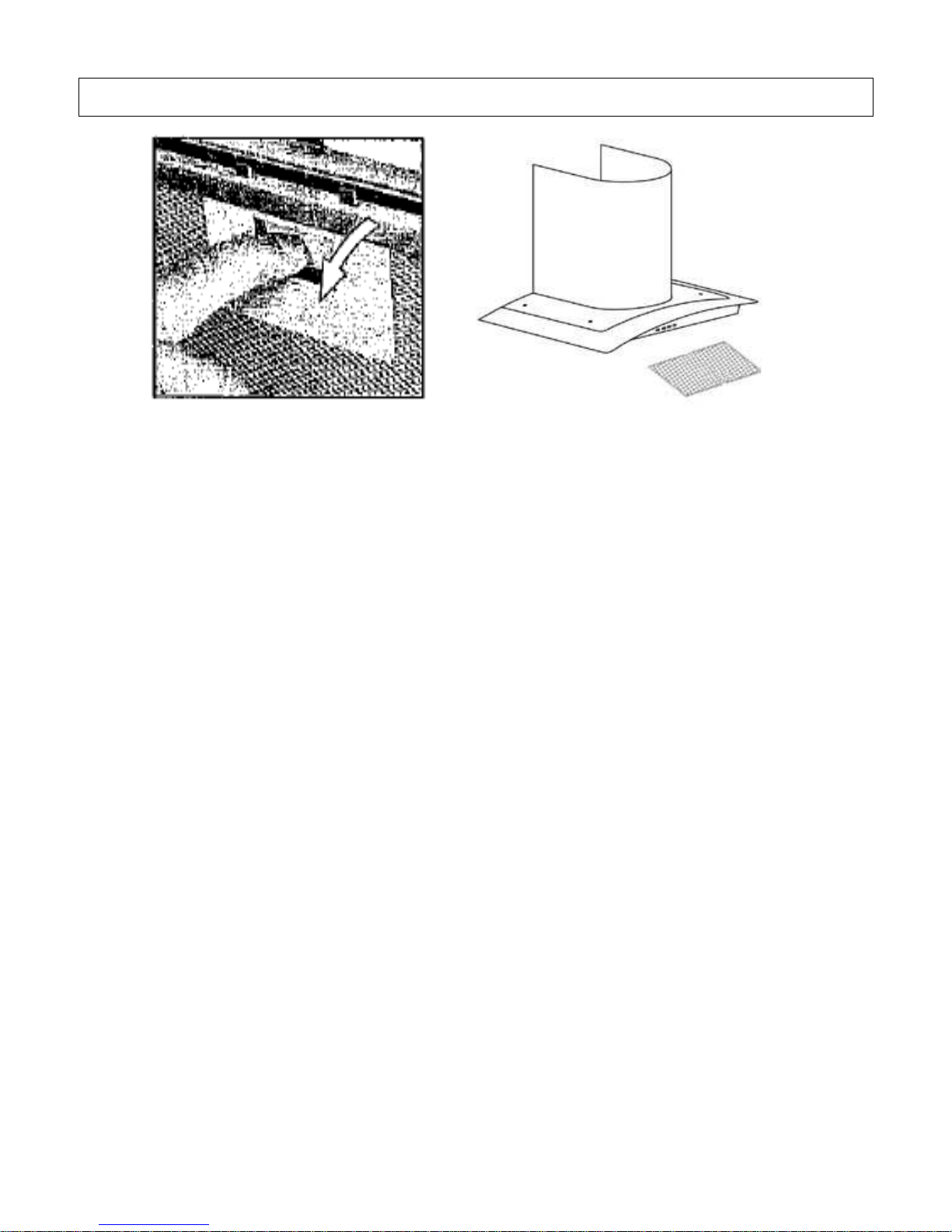
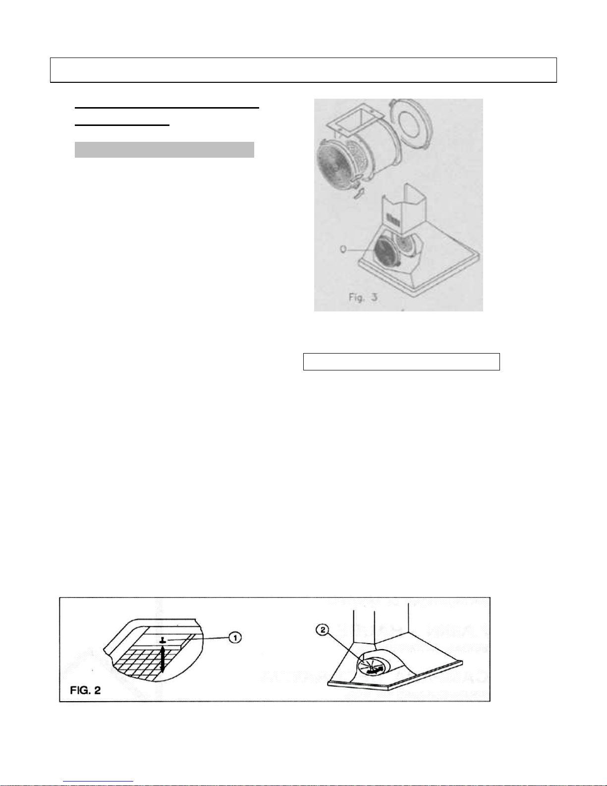
CHANGING THE CARBON FILTER
1) Press the handle of the metal grease
filter towards the rear part of the unit
until it is released from the front
housing, and remove it by pressing
downwards (Fig. 2 - above).
2) Remove the old carbon filters by
twisting them anticlockwise until they
unlatch from the sides of the motor.
3) Place the new carbon filters (which
have two fixing tongues), turning
clockwise so that the tongues latch
onto the motor’s sides. (Fig. 3 - left).
4) Reposition the anti-grease metallic
filter grilles.