6
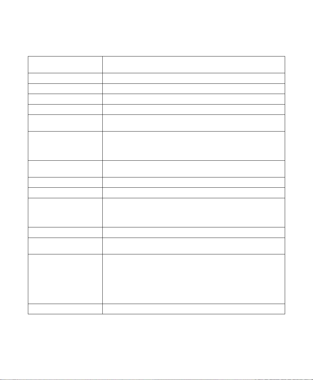
OSD Function Descriptions
FUNCTION DESCRIPTION
Brightness 101 scales of brightness are available to choose from (0 to 100)
Contrast 256 scales of contrast are available (0 to 255)
H. Position For adjustment of the display’s horizontal position.
V. Position For adjustment of the display’s vertical position.
Phase 32 scales are available to adjust the focus and clarity of the display (0
to 31).
Clock This function provides a frequency-tracking feature that allows the
user to have better stability and clarity. Increasing the Clock value
can be up to 64 settings. The number of decreasing Clock (minus) is
dependent on the video signal timing.
Auto Adjustment This function will adjust the display size automatically to fit the full
screen.
OSD H. Position For moving the OSD menu window horizontally.
OSD V. Position For moving the OSD menu window vertically.
Graphics Text Provides ability for the operator to choose a display that allows maxi-
mum graphics text quality. The resolution selection can either be
640x400 or 720x400. Please refer to Standard Timing Table for dif-
ferent timing modes.
Recall Will force all adjusted parameters to factory-preset values.
Language Five OSD language options are available: English, German, French,
Spanish and Italian.
Color Temp. Push the (+ -) buttons to select different color temperatures.
9300 – CIE coordinated Color Temperature of 9300ºK
6300 – CIE coordinated Color Temperature of 6500ºK
USER – Three colors (Red, Green, Blue) can be adjusted from the
OSD menu.
Save + Exit Saves the values of this setting and exits the OSD menu function.