Hope Industrial Systems HIS-ML18 User manual

Hope Industrial Systems, Inc.
User Manual
18” Industrial LCD Monitor
Model No. HIS-ML18

2
TABLE OF CONTENTS
Safety and Regulatory Information.............................3
Factory Preset Timing................................................4
Panel Controls and OSD Functions ...........................5
Power Button / Indicator.........................................6
OSD (On-Screen Display) Adjustment Controls.....6
Secondary Menu Settings ......................................8
Installation Instructions ............................................11
Cleaning...................................................................13
Troubleshooting.......................................................14
Drawings..................................................................15
Specifications...........................................................17
Warranty Statement.................................................20

3
Safety and Regulatory Information
Warning
To prevent fire or shock hazard, do not expose the unit to rain or moisture.
Dangerously high voltages are present inside the unit. Do not disassemble the
unit. Refer servicing to qualified personnel only.
This equipment is not intended for use in critical applications where its failure
to operate would create immediate life threatening circumstances. Applica-
tions including, but not limited to, nuclear reactor control, aerospace naviga-
tion systems and life support systems are not appropriate for this product.
This product is intended to be mounted in a suitable cabinet or other enclosure.
The NEMA 4, 4x or 12 ratings are applicable only when properly installed in a
like rated enclosure.
This product is a UL Recognized Component and must be used with a listed
computer.
FCC Notice
This equipment has been tested and found to comply with the limits for a Class A digital device,
pursuant to Part 15 of the FCC Rules. These limits are designed to provide reasonable protection
against harmful interference when the equipment is operated in a commercial environment. This
equipment generates, uses and can radiate radio frequency energy and, if not installed and used in
accordance with the instruction manual, may cause harmful interference to radio communications.
Operation of this equipment in a residential area is likely to cause harmful interference in which case
the user will be required to correct the interference at his own expense. Any changes or modifica-
tions not expressly approved by the grantee of this device could void the user’s authority to operate
the device.

4
Factory Preset Timing
Resolution
Horizontal
Freq. (KHz) Vertical
Freq. (Hz) Scan
Type
Pixel Frequency
640 x 350 31.470 70 ** N.I. 25.175
640 x 480 31.470 60 N.I. 25.175
Mac 35.000 67 N.I. 30.24
37.900 72 N.I. 31.50
37.500 75 N.I. 31.50
720 x 400 31.470 70 N.I. 28.321
800 x 600 35.100 56 N.I. 36.00
37.880 60 N.I. 40.00
48.100 72 N.I. 50.00
46.880 75 N.I. 49.50
832 x 624 Mac 49.800 74.6 N.I. 57.29
1024 x 768 48.360 60 N.I. 65.00
56.500 70 N.I. 75.00
60.020 75 N.I. 78.80
Mac 60.24 75 N.I. 80.00
* 1280 x 1024 63.98 60 N.I. 108
* Factory recommended timing for best picture quality
** N.I. = non-interlaced

5
Panel Controls and OSD Functions
ML18 power and video adjustment controls are located on the rear of the monitor. All monitor vid-
eo adjustments are made via the OSD (On-Screen Display) controls.
U
U
POWER
MENU
-
+
POWER
MENU
-
+
Power indicator light
Toggles power On/Off
1. Scrolls up the highlighted bar.
2. Increases the value of a parameter.
1. Scrolls down the highlighted bar.
2. Decreases the value of a parameter.
1. Activates the OSD on-screen display menu.
2. Selects a parameter for adjustment.
3. Exit or save the adjustment and return to the Main menu.
OSD Control Keys

6
Power Button / Indicator
Power Button
Toggles monitor on/off after power is supplied to the monitor.
The monitor automatically powers On when power is initially ap-
plied. This means that the monitor will always power-On after a
power outage -- the monitor cannot be left in a permanent Off
condition.
Power Indicator
Light
No light indicates that the monitor is off and/or no power is being
supplied to the monitor. When the monitor turned On, a yellow
light is briefly displayed while the monitor is attempts to sync.
Once sync is establish the light turns green.
OSD (On-Screen Display) Adjustment Controls
Use the following steps to select a menu item:
Step 1: Press the Menu key to activate OSD on-screen display.
Step 2: Press
+
or
-
key to scroll the highlight bar up or down the Main Menu.
Step 3: Press the Menu key to enter into the secondary menu.
Main Menu
-(Down) +(Up)
Brightness 35
Contrast
50
Auto Adjust
H Position
75
V Position
29
Color
►
Clock
►
Languages ►
Input Type ►
Factory Reset ►
Cancel ►
Save & Exit ►
A1 1024x768 – 60.1 48.4K
Hightlighted bar
Input Type
Note:
OSD menu will be
nullified after 30
seconds of inactive
period.
Resolution – Vert Sync
Hori Sync

7
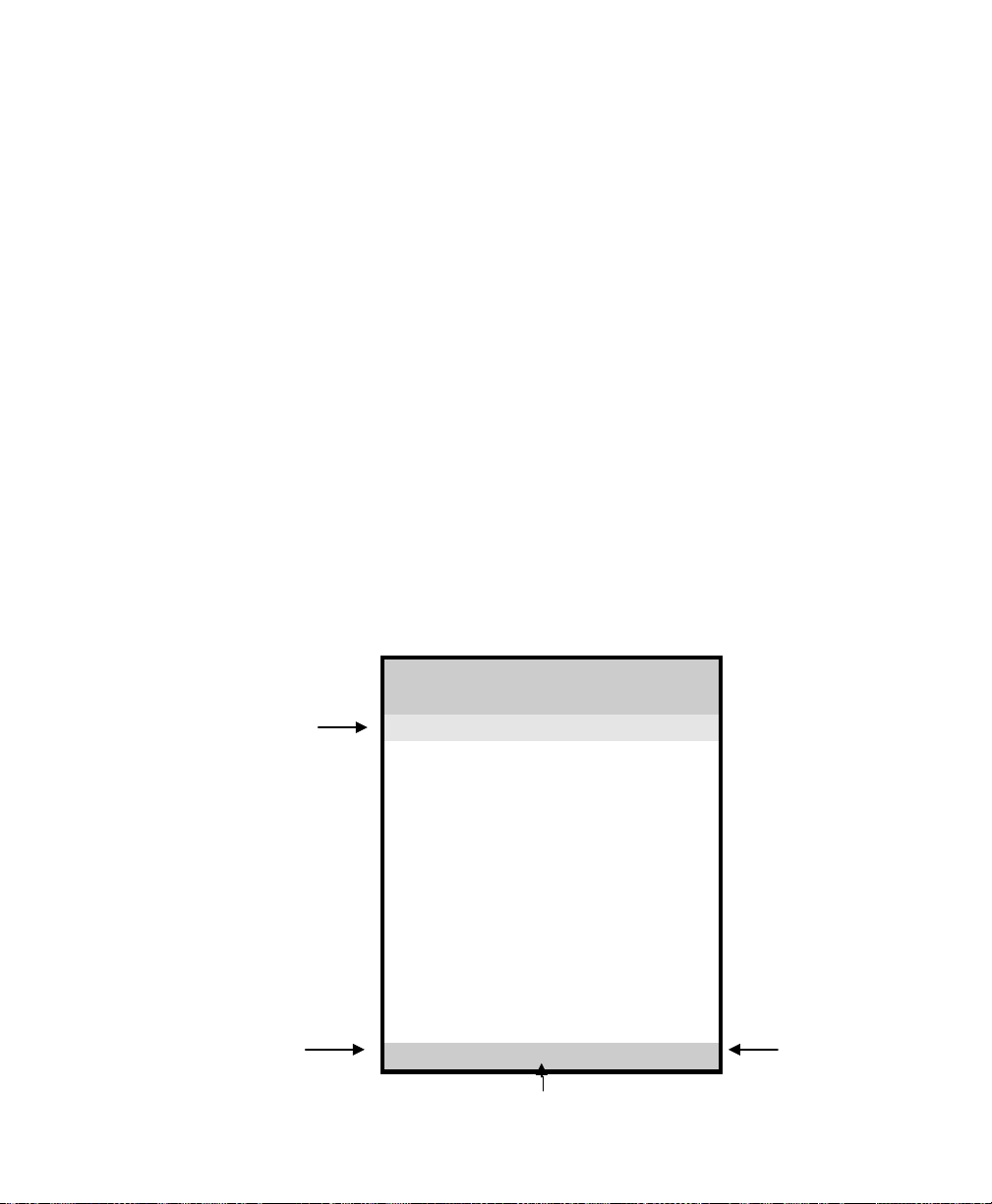
The color of the highlight bar indicates the status of the mode. RED indicates the
function is selected and ready to be adjusted. Blinking RED indicates OSD is in pa-
rameter adjusting mode.
Function Description
Brightness Adjust the overall image and background brightness level.
Contrast Adjust the image brightness in relation to the background.
Auto Adjust * Automatically set the H Position, V Position and Clock.
Horizontal Position*
Moves the screen horizontally left or right.
Vertical Position* Moves the screen vertically upwards or downwards.
Color
Adjust parameters for the screen colors of Red, Green and
Blue. Use +or -
key to scroll the highlight bar up or down
the Color menu.
Clock Adjust the function only when characteristics are blurred.
Languages Select English, French, Italian, Ge
rman and Spanish for OSD
language display on your own preference.
Input Type Select Analog (A1), DVI-A (A2), DVI-D (D), and S-
Video
(SV) input sources.
Factory Reset ** Reset the monitor to default or factory settings.
Cancel Restore the previous setting.
Save & Exit Save the adjustments and quit the OSD menu.
* The Auto Adjust and Horizontal/ Vertical Position can’t function under the S-Video input type.
* Auto Adjust function will be automatically executed whenever the system is switched to a new
mode. When the system is changed to this mode again later on, the system will not repeat the
Auto Adjust function. This function is only valid when the mode concerned is selected for the
first time.
** Execute Factory Reset function whenever you change your VGA card.
NOTE:
The bottom line of the OSD shows the input type, current resolution of the monitor and status of
vertical sync. If it shows user mode, please refer to the monitor Preset mode.

8
Secondary Menu Settings
Brightness
Use +or -key to increase or decrease the numerical level of brightness of the
screen.
Contrast
Use +or -key to increase or decrease the numerical level of contrast of the screen.
Auto Adjust
Activates when selected. Automatically adjust horizontal position, vertical position
and clock.
Horizontal Position
Use +or -key to increase or decrease the data by moving the screen to the right
or to the left.
Vertical Position
Use +or -key to increase or decrease the data by moving the screen up or down.
Color
Displays the following menu when activated from the main menu.
Color Menu
-(Down) +(Up)
Auto Balance
Balance (R-G-B)
Red
68
Green
65
Blue
70
Sharpness
1
Main Menu ►
A1 1024x768 – 60.1 48.4K
Once the desired menu item has been highlighted, press the Menu key to selected the item
for adjustment or activation. Below is the description of items in the Color menu:

9
Function Description
Auto Balance Autom
atically adjust the contrast level of RGB and does
not support resolution of Mac 832 x 624 at 75Hz.
Balance (R-G-B) Adjust the values of RGB proportionally.
R Adjust the level of color Red.
G To adjust the level of color Green.
B To adjust the level of color Blue.
Sharpness To adjust the level of sharpness.
Main Menu To return to Main Menu.
NOTE: The color menu can’t function under S-Video input type.
Clock
Displays the following menu when activated from the main menu.
Clock Menu
-(Down) +(Up)
OSD Position
Clock 1344
Clock Phase 4
Patterns
0
Main Menu
►
A1 1024x768 – 60.1 48.4K
Function Description
OSD Position Displays the OSD to your preference position.
Clock *
Adjust the function only when characteristics are blurred.
Clock Phase * Adjust ADC sampling clock phase.
Patterns
Displays the built-in test patterns. These are for factory
testing only.
Main Menu Returns to Main Menu.
* NOTE: The Clock and Clock phase function can’t function under S-Video input type.

10
Languages
Press +or -key to move the highlight bar up and down the menu and choose a language
by pressing <Menu> key. Upon the selection, the OSDs will be displayed in that language.
The languages include English, French, Italian, Deutsch and Spanish.
Input Type
Use +or -key to select the Analog (A1), DVI-A (A2), DVI-D (D) for PC application or
S-Video (SV) for DVD/VCD application.
Factory Reset
Activates when selected. Restores monitor to factory settings..
Cancel
Activates when selected. Restores monitor to previouse settings
Save & Exit
Activates when selected. Saves adjustments and quits OSD Menu.

11
Installation Instructions
Preparing for Installation
Important! Perform the following steps BEFORE Installation of the moni-
tor into the panel.
1. Ensure that sufficient power is available.
2. Ensure that sufficient space is available to allow for proper airflow into and
out of the unit.
3. Ensure that the air temperature around the unit (top and bottom) will not ex-
ceed the rated specifications of the unit.
The maximum rated temperature of the HIS-ML18 is 45
°
C (113
°
F)
when properly ventilated with moving air across the back of the
unit– consult the factory for installation instructions when conti-
nuous 24/7 operation exceeds 40
°
C (104
°
F).
Remember that heat rises – the temperature at the top of the cabi-
net will be much hotter than at the bottom when the air is not cir-
culating.
Also, remember that even though this product is designed to oper-
ate at 45
°
C with proper ventilation, the life span of any electronic
device is shortened when it is consistently operated at high tem-
peratures. Therefore it is wise to take steps to keep the tempera-
ture of the ambient air around the unit as low as possible.
4. Ensure that the ambient humidity of the air around the unit does not exceed
the rated specifications for the unit
The maximum rated humidity for the HIS-ML18 is 90% non-
condensing

12
Installation into Panel
1. Refer to the drawing below.
2. Locate position in panel for mounting of the monitor. Assure that there
is adequate space begin the panel. Allow extra space (0.5 in. behind and
on each side) for air ventilation.
3. Cut a rectangular hole in the panel. Clean and deburr.
Dimensions: 17.85” (454mm) W x 14.44” (367mm) H ; +/- .020”
4. Separate the rear collar from the unit by removing the 14 nuts.
5. Insert the unit into the front of the panel and re-attach the collar.
6. Tighten all 14 nuts to a torque of 24 inch-pounds to assure a water-tight
seal between the poron bezel gasket on the monitor and equipment panel.
HIS will not assume liability for damage to internal electronics due to
improper installation.

13
Cleaning
Resistive Touchscreen model
Any standard glass cleaner can be used to clean the touchscreen.
Always spray the glass cleaner on the cloth or towel and then clean
the touchscreen. Glass cleaner sprayed directly on the monitor could
possibly leak inside a non-sealed unit and cause damage.
Vinegar or ammonia will not hurt the touchscreen. Again, spray the cloth
and then clean the touchscreen.
Tempered Anti-Reflective Glass Window
Use any standard glass cleaner as long as there is no abrasive or oily con-
tent. The anti-reflective coatings are physically part of the surface of the
glass and resist degradation to the Military Specifications.
Acrylic Bezel
The acrylic front bezel can be cleaned in the same manner as the touch-
screen or glass window.

14
Troubleshooting
Blank Screen After installing the power adapter and connecting I/O cable to a PC, the
monitor displays a blank screen.
•Press the power button and check to see if the power LED is lit.
•If the LED is not lit, make sure the PC is powered on. Make sure all
cables are connected.
•If the LED stays yellow, check to see if the PC is in the power saving
mode by pressing any keys on the keyboard.
Rolling Screen
•Change PC display resolution to 1280x1024 at 60hz.
•Unplug the power adapter to monitor, then plug it in again.
•Press monitor power button again.
•Reset the monitor to the original factory setting.
•Press “Auto Adjust” button on OSD menu.
Unstable Screen
•Select “Auto Adjust”.
•Make sure the PC display resolution is not set greater than
1280x1024 at 60hz.
•Make sure the PC display resolution matches one of the factory-
preset timings in this manual.
•Change the PC display resolution to 1280x1024 at 60hz.
•Reset the monitor to the factory setting.
•Select “Auto Adjust”.
Screen is not perfect
•Make sure the PC display resolution matches one the factory preset
timings shown in this manual.
•Recall factory setting. Refer to panel controls and OSD functions in
this manual.
•Fine-tune the picture by performing the following adjustments in this
order – pitch, phase, and position. Refer to OSD functions in this
manual.

15
Drawings
Front and Side Views
Bottom View

16
Rear View (showing cutout dimensions)
Cutout tolerances are +/- .5mm [.02”]

17
Specifications
Display
Type
Thin-film transistor (TFT) Active Matrix Liquid Crystal
Size
18.1” diagonal
Image size
14.1” (359mm) x 11.3” (287mm)
Native resolution
SXGA (1280 x 1024) @ 60 Hz
Plug and Play
DDC1/2B compatible
Minimum resolution
VGA (640 x 350), operation in native resolution (1280 x
1024) will ensure best results
Pixel pitch
0.281mm (H) x 0.281 mm (V)
Number of colors
16M (24 bit)
Viewing Angle (Hori/Vert)
160
°
/ 160
°
, typical
Brightness (white)
200 nits (cd/m2) min
Contrast ratio
300:1 (min.)
Back light 4 CCFTs (Cold Cathode Fluorescent Tube); 30,000 hours,
half-life; replaceable
Screen protector (when
not shipped with touch-
screen)
Tempered glass to ANSI-Z97.1 SPEC; AR coated on both
sides; 98% Transmission of light; 99% Reduction of glare;
53% UV blocking; 30% NIR Blocking; proprietary hydrophob-
ic coating on outside reduces fingerprint smears, repels liq-
uid spills and makes glass easy to clean.
Video
Input connector
HD-15 plus optional DVI digital input
Input signal format Analog RGB signals, DVI Analog/Digital, S-Video, 0.7 Vp-p
Horizontal scan 31kHz – 64kHz
Supported Video Stan-
dards Std VGA – 640x480 @ 60Hz
SVGA – 800x600 @ 60Hz
XGA – 1024x768 @ 60Hz
1280x1024 @ 60 Hz (native)
Vertical scan 56Hz – 75 Hz
Response rate (typical) 50 ms (typ.)

18
Electrical
Power Adapter Input
100VAC – 240VAC, 50-60 Hz
Power adapter output
12VDC @ 5.2 amps
Monitor input
12VDC
Power consumption
Approximately 48 watts
Power management
DPMS/energy star, < 3W
Compliance
UL 1950, cUL 959; FCC Class A
Environmental
Temperature
0-45°C (consult factory for installation instructions when con-
tinuous 24/7 operation exceeds 40
°
C)
Humidity
20% to 90% non-condensing
Shock
30g (1/2 sine, 11 msec.)
Vibration
0.006 inch p-p 15-57Hz, 1.0g 57-640Hz sine
Altitude
Operating: up to 10,000 feet; Non-operating: up to 40,000
feet
Functional
Panel controls (rear
access) Power On/Off switch, Keys for controlling OSD (On-Screen-
Display).
OSD (On Screen Display)
controls Brightness, Contrast, Color, H-position, V-position, Clock,
Phase, Input Signal, Source, OSD Position, Language, Auto-
Adjust, Auto-Balance, Factory Reset.
Touch screen option Elo Touch systems AccuTouch 5-wire resistive system;
emulates a mouse; RS-232 interface to host computer
Rack mount option
Fits in standard 19” EIA rack, 9U height

19
Enclosure
Type Panel mount; rear collar compresses gasket against panel,
held by 14 10-32 studs
Panel rating
NEMA 12/4/4X (with proper installation) – built to IP65 stan-
dards
Physical
Depth
2.5” (64mm) behind panel maximum
Bezel
Acrylic - matte finish, black; or Stainless Steel
Front bezel outside di-
mensions 19.0” (483mm) W x 15.7” (399mm) H x 0.236” (6mm) thick
(not including gasket)
Cutout dimensions 17.60” (452mm) W x 14.40” (366mm) H ; +/- .020”
Net weight
19 lbs.
Shipping weight
25 lbs.
VGA Pin assignment
Pin No. Signal Pin No. Signal
1
Red
9
No pin
2
Green
10
Ground
3
Blue
11
Ground
4
Ground
12
SDA
5
Ground
13
H. sync
6
Ground
14
V. sync
7
Ground
15
SCL
8
Ground

20
Warranty Statement
Who is Covered?
This warranty covers the purchaser of this product only and is not transferable without our written
consent.
What Does This Warranty Cover and What is the Period of Coverage?
We warrant this product to be free from defects in material and workmanship, subject to the condi-
tions set forth below. This warranty remains in force for a three-year period beginning on the date
we invoice you for the product. If HIS repairs or replaces a product under warranty, its warranty
term is not extended.
What Will We Do to Correct Problems and How Do You Get Service?
We will repair or replace (at our sole option) any part of the unit which proves to be defective. Re-
placement parts may be new or refurbished and will meet the same specifications of the original
parts or unit. We will return the product to you, by the shipping method we choose in the U.S.A. at
our expense. You must pay for shipments to locations outside of the U.S.A. In order to receive war-
ranty service you must get prior approval from HIS. To request warranty service you can telephone
us at 770-992-0297 or send an email to service@HISmonitors.com. If we determine that warranty
service is needed we will give you a Return Material Authorization (RMA) number. This RMA
number must be conspicuously marked on the outside of the shipping box. HIS will not accept
shipments not accompanied by the RMA number. You must ship or deliver the product to HIS
Freight prepaid.
Pixel Faults
Permanently dark or bright pixels can happen to TFT displays. Five or less permanently dead pixels
(out of 1.3 million) do not make a good case for exchanging the unit. Please contact our Customer
Service Department if the number of pixel faults exceeds the above-mentioned figure.
What Does This Warranty Not Cover?
This warranty does not cover equipment which has been damaged due to misuse, abuse or accident
such as: operating the equipment outside of published specifications; displaying fixed images for
long periods of time resulting in afterimage effects; improper or unauthorized repair by anyone other
than HIS or a service agency authorized by HIS to perform such repairs; fire, flood, “acts of God”,
or other contingencies beyond the control of HIS.
HIS’ RESPONSIBILITY FOR MALFUNCTIONS AND DEFECTS IN HARDWARE IS LIMITED TO REPAIR AND
REPLACEMENT AS SET FORTH IN THIS WARRANTY STATEMENT.HIS SHALL NOT BE LIABLE FOR DIRECT,
INDIRECT,INCIDENTAL,CONSEQUENTIAL,OR OTHER TYPES OF DAMAGES RESULTING FROM THE USE OF
ANY HIS PRODUCT OTHER THAN THE LIABILITY STATED ABOVE.THESE WARRANTIES ARE IN LIEU OF
ALL OTHER WARRANTIES EXPRESS OR IMPLIED,INCLUDING,BUT NOT LIMITED TO,THE IMPLIED
WARRANTIES OF MERCHANTABILITY OR FITNESS FOR A PARTICULAR PURPOSE.SOME STATES DO NOT
Hope Industrial Systems
Other manuals for HIS-ML18
1
Table of contents
Other Hope Industrial Systems Monitor manuals

Hope Industrial Systems
Hope Industrial Systems IS-UM17 B Series User manual

Hope Industrial Systems
Hope Industrial Systems HIS-ML22 C Series User manual

Hope Industrial Systems
Hope Industrial Systems HIS-ML12-SXA User manual

Hope Industrial Systems
Hope Industrial Systems HIS-ML21-*** D series User manual

Hope Industrial Systems
Hope Industrial Systems HIS-RL17-H Series User manual

Hope Industrial Systems
Hope Industrial Systems HIS-ML21-CGBC User manual

Hope Industrial Systems
Hope Industrial Systems HIS-ML18B User manual