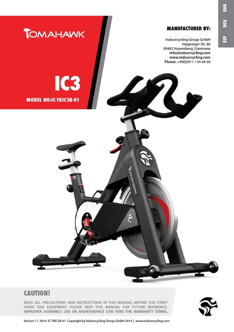
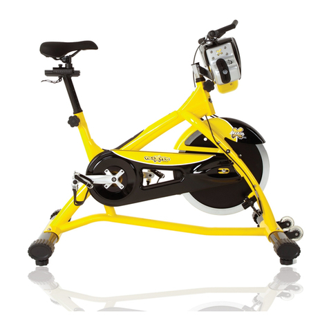
Hope 1005PKS-MA User manual

USER MANUAL
INDOOR BIKE
Be Sure to Read This Manual before Assembling and Using

- 2 -
CONTENTS
SAFETY GUIDELINE………………………………………3
PARTS LIST……………………………….......................6
INSTALLATION……………………………………………10
NOTICE…………………………………………………14

- 3 -
SAFETY GUIDELINE
Regular maintenance of the bike should be performed and is essential to keep your Spin bikes in top
operating condition. Without preventative maintenance, normal wear and tear may cause cumulative effects,
such as misalignment or early replacement of parts.
1. Once assembled, please inspect to ensure that all hardware parts such as bolts, nuts and washers are
positioned and correctly.
2. Be sure to wear shoes when exercising, and tighten pedal cage and straps.When using SPD shoes, make
sure that the buckle is fully inserted.Do not remove your foot from the pedal while the bike is still in
motion. If your facility allows members to interchange pedals, it is critical that the pedals are checked
after each class to prevent damage and possible injury.
3. We recommend lubricating all moving parts on a monthly basis.
4. Water bottle cages are easily damaged during class when over-sized bottles are forced to fit within them.
Checking and tightening the screws will help prevent damage.
5. Wipe down the bike at the end of each class. Consider using mildly alkaline cleaning or neutral cleaning
liquids, never use water or oil based cleaning liquids when wiping down the bike.
6. Please keep children away while riding, the bike is designed for adults, and is not suitable for children.
7. If you have any pain or tightness in your chest, an irregular heartbeat, shortness of breath, feel faint or
have any discomfort while you exercise, STOP!
8. Do not place fingers or any other objects into moving parts of the exercise equipment. Do not wear loose
clothes, in case any possible parts getting involved.
9. Before starting any exercise program, consult with your physician first. He or she can help establish the
exercise frequency, time and intensity appropriate for your particular age and condition.
10. After exercising, please turn the adjustment control knob clockwise (+) to increase tension so the pedals
will not rotate freely and possibly hurt someone.
11. This spin bike has passed the standard test of EN 957-1:2005 and EN 957-10:2005, suitable for
commercial use. The max user weight should be within 150kg, and should use under surveillance.

- 4 -
INSPECTION
Ensure to inspect all major moving parts such as the saddle, pedals, handlebars and tension wheel on a
regular basis.
Pedals: Ensure that pedals are tightened frequently to prevent them from becoming loose.
Adjustment slider: Check the seat adjustment slider and handlebar adjustment slider regularly to ensure that
they are locked in place.
WHAT TO WIPE DOWN
Using an absorbent cloth, focus on all areas where perspiration can settle. Raise all posts to the highest
setting to expose this moisture.
Handlebar
Flywheel
Front leg assembly
Back leg assembly
Chain guard
Brake knob and bolt assembly
Pop pins
Base leveler

- 5 -

- 6 -
Part List
No.
DESCRIPTION
SPECIFICATION
QTY
1
Frame
1
2
Rear Base
Flat Oval 40*120*498L
1
3
Front Base
Flat Oval 40*120*498L
1
4
Seat Post
30*70*3T*527L
1
5
Handlebar Post
30*70*3T*330L
1
6
Seat Support
21*48*240
1
7
Handlebar Support
21*48*180
1
8
Handlebar
1
9
Handle Knob Cover
2
10
Handle Knob
2
11
Sync Block
2
12
Hexagon Nut
M8
2
13
Washer
φ16*φ8.2*2T
6
14
Spacer Pin
φ4*18
1
15
Inner Hexagon Column Screw
M4*8
12
16
Seat Support Decoration Cover
4
17
Handlebar Slider
Length:179mm
2
18
T-Shape Bolt
M8*45
2
19
Inner Hexagon Column Screw
M6*14
2
20
Seat Post Decoration Cover
4
21
Cyclinder Hexagon Socket Screw
M5*20L
4
22
Inner Hexagon Column Screw
M5*12
2
23
Handlebar Rack
23.5*2T*234
1
24
Cross Countersink Screw
M5*16
10
25
Seat Rack
23.5*2T*405
1
26
Seat Slider
4.1*10.2*239
2
27
Right Pedal
1
28
Pedal Feet Sheath
2
29
Pedal String
2
30
Right Crank Cover
1
31
Hexagon Flange Nut
M12*1.25
2
32
Right Crank
1
33
Outer Hexagonal Bolts
M8*16
4
34
Axle Welding
Ø25*167.5L,Square16.1
1
35
Plastic Belt Wheel
Ø210*23W
1
36
Belt
5PK 1330MM
1
37
Bearing
6005-2RS
2
38
L-shape Handle
M16*P1.5
2
39
Rear Inner Pipe Sheath
1
40
Aluminium Braking Knob
M10
1

- 7 -
41
Braking Pole
Ø12*M12*P1.75*270L
1
42
Plastic Sheath
Ø22*Ø12.5*40L
1
43
Sheath
φ16*φ12*20L
1
44
Braking Limited Block
□16*16*33L
1
45
Hexagon Nut
M8
1
46
Hexagon Cap Nut
M8
1
47
Brake Holder
156.1*115.7*4T
1
48
Brake Pad
55*12*8.8T
1
49
Magnet Holder
2.5T
2
50
Magnet
φ25*8T
6
51
Inner Hexagon Column Screw
M10*50L
1
52
Washer
Φ20*Φ10*1.5
6
53
Torsion Spring
φ2.8
1
54
Hexagon Nylon Nut
M10*10T
1
55
Corrugated Mat
Φ32*Φ25.5*0.3T
2
56
L&R Water Bottle Holder
2
57
Hexagon Thin Nut
M12*1.0*6T
3
58
Left Crank
1
59
Left Crank Cover
1
60
Left Pedal
1
61
Front Inner Pipe Sheath
1
62
Base Leveler
M10
4
63
Hexagon Nut
M10
4
64
Washer
Φ20*Φ10*1.5
8
65
Inner Hexagon Flat Round Screw
M10*25L
4
66
Hexagon Socket Hollow Screw
Φ8*M6*30L
2
67
Bearing
608ZZ
4
68
Transportation Wheel
2
69
Inner Hexagon Flat Round Screw
M6*12L
2
70
Hexagon Flange Nut
M12*P1.0
2
71
Axle protecting Sheath
φ16*φ12.2*8L
2
72
Flywheel Axle
φ12*M12*P1.0*154L
1
73
Bearing
6001
2
74
Nylon Nut
M8
6
75
Flywheel Aluminium Circle
Φ430*Φ336*7T
1
76
PK Magnetic Flywheel
Ø360*38W
1
77
Flywheel Sleeve
φ16*φ12.1*27.5L
1
78
Decoration Cover of Flywheel(L)
1
79
Washer
φ5..2*φ10*1.0T
4
80
Cross Pan Screw
M5*15L
12
81
Chain Cover A
1
82
Chain Cover B
1
83
Front cover
1
84
Front Inner Pipe Cover
1

- 8 -
85
Cross Umbrella Head Screw
M5*10
4
86
Inner Hexagon Column Screw
M6*18
2
87
Chain Cover A
1
88
Washer
Φ25*Φ8*1T
1
89
Tension Spring
Φ3.0*17
1
90
Tension Wheel
φ37*φ30*24.5
1
91
Inner Hexagon Flat Round Screw
M8*27L
1
92
Spacer Pin
φ4*14
1
93
Seat
1
94
Rear Inner Pipe Sheath(Right)
1
95
Rear Inner Pipe Cover
1
96
Front Inner Pipe Sheath(Left)
1
97
Inner Hexagon Column Screw
M5*20L
4
98
Hexagon socket countersunk head screw
M5*25L
2
99
Hexagon nut
M24*P1.0*7T
1
100
Sleeve
Φ25.2*Φ32*54L
1
101
Computer
1
102
Console Mount
1
103
Philips Screws
M5*10
2
104
Cross Pan Screw
M5*10
2
105
Down Sensor Line
1
106
Up Sensor Line
1

- 9 -
INSTALLATION

- 10 -
Steps of Installation:
Step 1:Install Front Base and Back Base
Fix the Front Base (3) and Rear Base (2) to Main Frame (1) respectively with Washer Φ20*Φ10.1*1.5 (64)
and Inner Hexagon Flat Round Screw M10*25 (65).Then fasten them with Nylon Nut (54)by Inner Hexagon
tool.
Step 2:Install Left Pedal and Right Pedal
Loosing the Hexagon Socket Screw by 3# Hexagon Wrench.Then screw the Left Pedal (60) and Right Pedal (27) to
the Crank by hand for several turns.Fix them with Opening Wrench #15 in the tool kit.(Notice:The Right
Pedal screws in clockwise,and the Left Pedal screws in anticlockwise.) Re-tighten the Hexagon Socket
Screw by 3# Hexagon Wrench.

- 11 -
Step 3:Assemble the Seat Post
A. Remove the Inner Hexagon Column Screw(97) from the seat post(4).Insert the seat post(4) into the Rear Inner
Cover(95).Then tighten the Inner Hexagon Column Screw(97).
B. Loosen the L-shape handle(38),put the Seat Post(4) into the frame.Adjust the seat Post to the “Stop” position.Then
re-tighten the L-shape handle(38).
C. Tighten the Rear Inner Pipe Cover to the frame with Inner Hexagon Column Screw(97) and Hexagon socket countersunk
head screw(98).
A B C
Step 4:Assemble the Handlebar Support.
Invert Handlebar Post(5) and Handlebar Support(7),put the Handlebar Support(7) into the Handlebar
post(5),and then lock it with Inner Hexagon Column Screw M5*12(22).

- 12 -
Step 5:Assemble the Handlebar Post
A.Remove the Inner Hexagon Column Screw(97) from the Handlebar post(5).Insert the handlebar post(5) into the Front
Inner Pipe Cover(84).Then tighten the Inner Hexagon Column Screw(97).
B.Loosen the L-shape handle(38),put the Seat Post(4) into the frame.Adjust the seat Post to the “Stop” position.Then
re-tighten the L-shape handle(38).
C.Tighten the Rear Inner Pipe Cover(84) to the frame with Inner Hexagon Column Screw(97) and Hexagon socket
countersunk head screw(98).
A B C
Step 6:Assemble the Computer
Tighten the Console Mount(102)with Philips Screws(103),and then tighten the comsole(101) with Cross Pan Screw(104).

- 13 -
Step 7:Assemble the Seat
Put the Seat(85) into Seat Support(6),use the opening wrench to to fasten the Seat (clockwise direction).
Step 8:Installation Completed
After finishing installation, please inspect all the screws and nuts carefully to make sure all of them
tightened.

- 14 -
NOTICE
1.Before exercise, inspect all moving parts incl. saddle, handlebar, pedals etc regularly to ensure they are
tightened correctly.
2.If you need to move the bike, please grasp the Handlebar (8) at their very ends to make the Pulley (68) on
the Front Base stand on the floor, then the bike can be moved easily .
Table of contents