16xx Geyser 58L-ed4010
16xx GEYSER 58 7
3. Installation
3.1. Goods receiving
The appliance is delivered assembled on a pallet and protected by a
plastic film and/or a cardboard box.
1. Position the pallet with the appliance close to the installation
final destination. Move the pallet only with suitable means, such
as a fork-lift.
2. Remove the packaging material and separate the cardboard
from the plastic. Dispose or recycle the cardboard and plastic
according to local norms.
3. Unscrew the bolts that secure the appliance to the pallet
4. Move the appliance from the pallet to its final position.
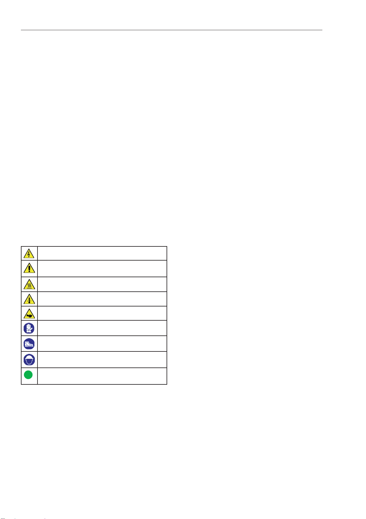
WARNING – The appliance can be moved by
hand only by experienced personnel. Wear
gloves, safety hat and safety shoes to move the appliance.
3.2. What’s inside the packing
The packing contains:
1. The appliance equipped with all its components.
2. User manual.
When receiving the goods, make sure that the packing contains all
the above listed items.
3.3. Electrical connections
WARNING - The electrical connection is to be made by
a licensed electrician only and according to local safety
regulations.
The manufacturer is not responsible for damage or injury caused by
improper installation.
1. Install a multi-pole switch (circuit breaker) to facilitate installa-
tion and service operations. See table 3.5 for rating and type of
connection.
2. In most countries the circuit breaker should include a pro-
tection against overcurrents (e.g. thermal-magnetic circuit
breaker or fuse). If using a fuse, see power absorption on
the identification plate of the appliance (see figure 2.1).
In some countries the circuit breaker must include a ground
fault interrupt protection.
3. If the appliance is not provided with power cord, mount a cord
of suitable length. For the choice of the cord type refer to table
3.5.
4. Mount a plug on the power cord, see table 3.5 for rating.
5. Connect the plug to the circuit breaker. The cable should hang
in a gentle curve.
WARNING -The electrical line must be properly grounded
to insure the safety of the operator.
INDICATION - If a Ground Fault Interrupt protection is in-
stalled: every month test the safety of the circuit by press-
ing the Test button of the circuit breaker. The protection ought
to trip. If it does not, call a technician immediately, as the safety
of the equipment is impaired.
Table 3.5 - Data for electric connection
Type Plug Power cord
1638
IEC 60309 plug
3P+N+T 400V 3N 100 A
Type H05VV-F
5 x 25mm2
1645
1672 Type H05VV-F
5 x 35mm2
WARNING - The power cord can be replaced only by an
authorised service center.
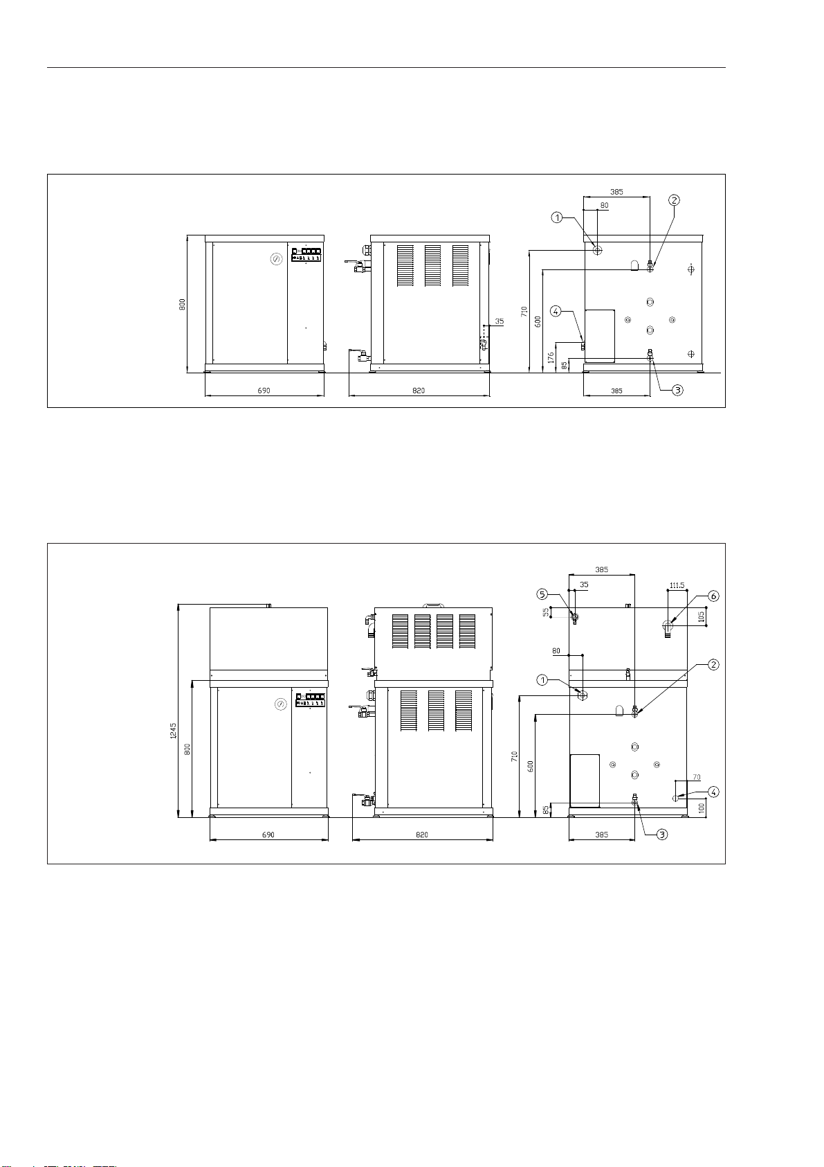
3.4. Water and steam connections
CAUTION – The connections must be performed by a
qualified technician according to the local regulations in
force.
Please refer to Pictures 3.1 and 3.2.
1. Connect the boiler discharge outlet C to a safe and permanent
connection, that can stand heat.
WARNING - The connection must ensure that no
leakage of steam or hot water occurs during the
boiler discharge operation
2. Connect the water inlet E to the water supply line.
• install a non-return valve* and a faucet or ball valve on
the water mains
• for the connection use a 16mm diameter tube rated for
the pressure of the water mains in your area*.
*For EU countries: these items must be approved according to
standard EN 61770.
WARNING - Use tap water. Do not add softening
products.
3. If the appliance is equipped with the top tank for condensate
recovery: connect the overflow of the tank F to a drain line.
WARNING - Water that overflows from the tank may
reach 80°C: choose a suitable pipe.
4. Connect the steam outlet B to the steam distribution plant.
WARNING – The steam distribution line must be rat-
ed to stand a working pressure of 800 kPa.
5. If the appliance is equipped with the top tank for condensate
recovery: connect the condensate return line to the condensate
inlet D on the tank. For convenience we suggest to install a
valve able to interrupt the flow of condensate.
6. Thermally insulate all the pipes that carry hot water or steam
(i.e. all the pipes except for the tube that feeds water).
7. If necessary, install tanks or devices that allow hot water to cool
before reaching the drainage system.
3.5. Training of the operator
The technician must instruct the operator on how to drain the boiler.
The operator must be advised that:
• during the operation, the boiler expels hot water mixed to
steam;
• the operation can be carried out only if the pressure in the boil-
er is below 1 bar;
• the connection to the drainage system must be kept in good
order and must be verified every time before performing the
procedures.
Installation