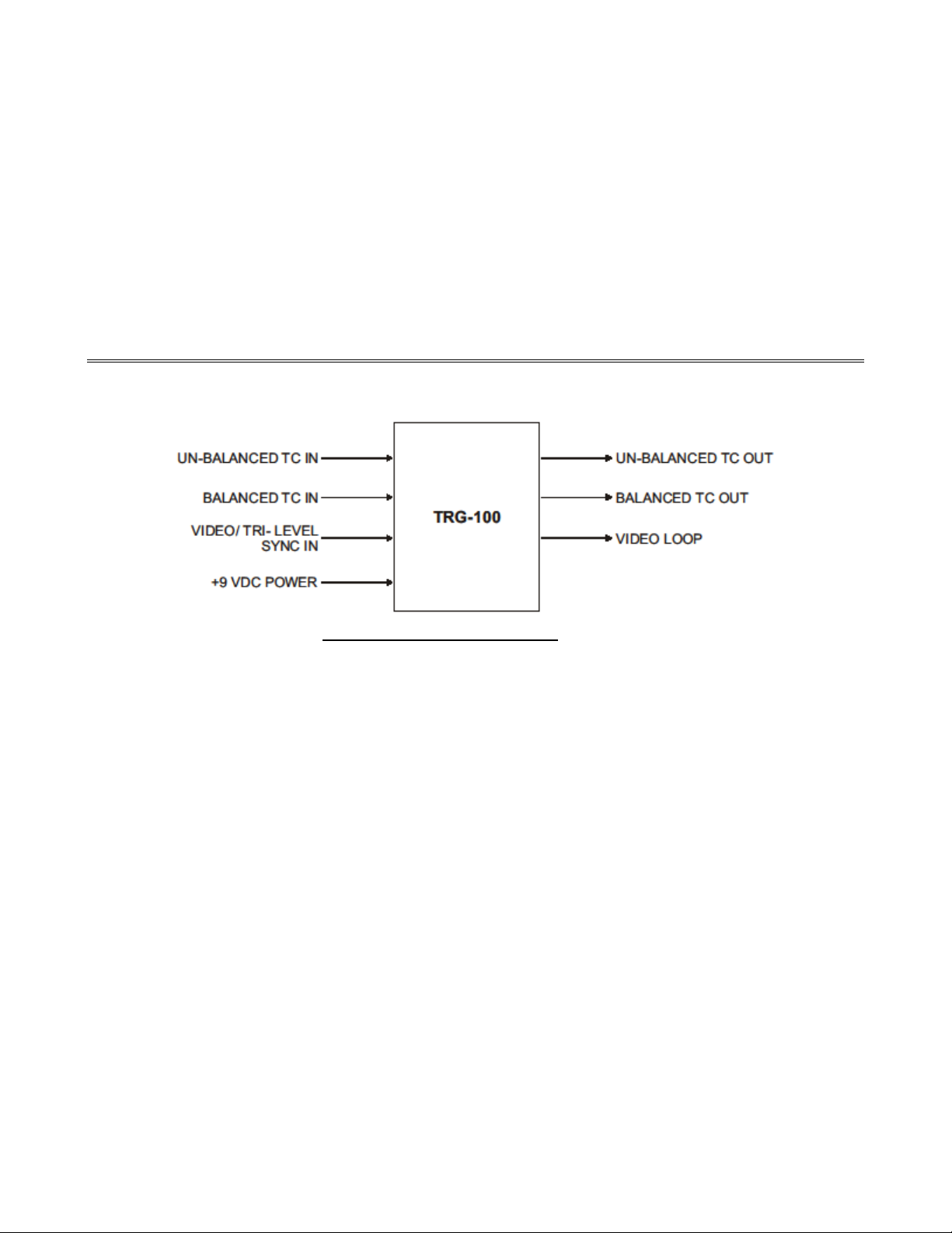
9
reference input FPS rate changes slightly, the TCG follows it so that they are maintained "in step" and locked together. The
TCG can be genlocked to either the time code being read by the TCR or to an external video reference input signal.
4.22 "Jamming" The TCG Time
The TCG time code value is jammed (automatically set) to the TCR time value when the TRG-100 MODE switch is
switched from TCR to TCG and the TCR has been reading valid play speed time code. After being switched to the TCG
mode, the actual jam operation takes place when the next frame number "00" of the time code is about to be read.
An exception to this automatic jam operation is made when the FPS is selected for display. When this is the case and the
MODE switch is switched from TCR to TCG, the TCG FPS is displayed without causing the TCG to jam or re-jam.
The jam process is such that when first switched from TCR to TCG, the TCR continues reading time code and flashing the
TCR LED at the TCR frame rate until frame 00 is the next frame of time code about to be read. When this occurs the TRG-
100 time code output is switched over from re-shaped TCR time code to TCG time code and the TCG is started. The TCR
LED is extinguished and the TCG LED starts flashing at the selected TCG frame rate.
If the TCR time code being read when is not valid or is not at play speed when the MODE switch is changed from TCR to
TCG, the jam operation is not performed and although the TCG is selected, it is stopped.
4.23 "Jamming" The TCG User Bits
The eight (8) TCG user bit characters are also jammed to a user selected source value at the same time that the time code
time value is jammed. The TRG-100 permits the user to select the UB jam source as the PRE1, PRE2 preset memory
values, or as the most current TCR UB values.
4.24 Selecting the Jam Source for the TCG User Bits
The jam source for the TCG user bits is determined by whatever user bit Preset memory is selected at the time the user bits
are jammed. For example, if both the PRE1 and PRE2 LEDS are ON, then the TCR user bits are the jam source for the
TCG user bits. The PRE1, PRE2, or TCR selection can be determined simply by displaying the TCG user bits and noting
the status of the PRE1and PRE2 LEDs.
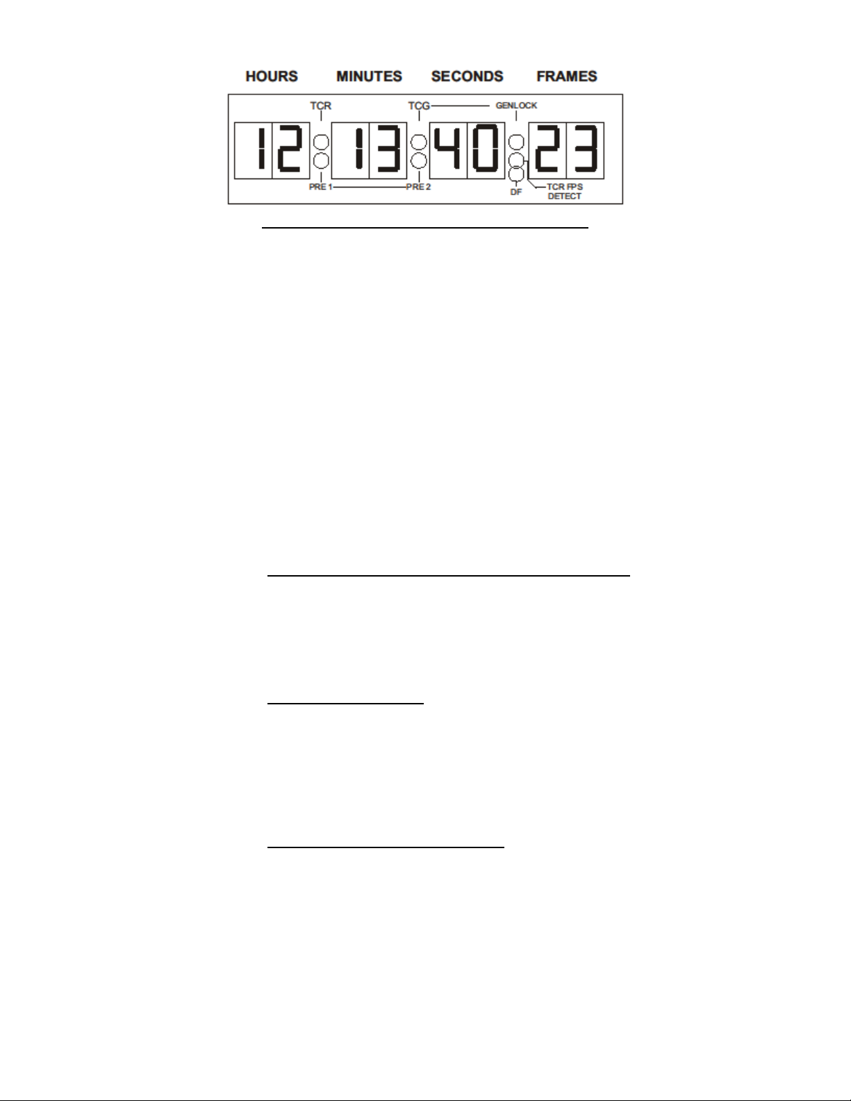
4.25 "Genlocking" The TCG
After the TRG-100 has been jammed to the source time, in most cases it can be kept "genlocked" to the jam source time
code or to a video/sync input to the TRG-100. Genlocked means phase locked and this in turn means that, for example, if
the frame rates of the TRG-100 time code IN and time code OUT are the same, and if the TRG-100 was genlocked to the
TCR by setting the GENLOCK switch to TCR, then both time codes would match exactly, with both being in step bit-for-
bit as they were being read and generated. When the TCR was reading the input bits for the units of frames, the TRG-100
would be outputting the exact bits for the units of frames.
When the time code is genlocked to video this means the TRG-100 starts generating the frames value of the time code
exactly at the start of the video frame, and ends with the time code hours value and sync pattern exactly at the end of the
video frame. This process is continuously repeated as each frame of time code and video is generated, and helps insure that
when a time code number is later read that it is for that particular video frame that it overlaid in time.
If the time code input to the TCR is the jam source but it is not locked to video, the TRG-100 can be setup to jam to the
TCR time but genlock to the input video by setting the GENLOCK switch selection to VID.
When genlocking, if the frame rate of the incoming video or time code and that of the TRG-100 generated time code do not
match, the TRG-100 can still be genlocked to the selected genlock signal as long as the frame rates of both resolve at each
second. This means that the 24, 25, 30, and 50 FPS frame rates for video or time code can all be genlocked to each other.
When genlocking in this manner the genlock status is checked on frame 00 of each new second. This is referred to as "PPS"
(Pulse-Per-Second) genlock. When the TRG-100 is performing PPS genlock it may take several seconds for the
"GENLOCK" LED to start flashing at 1-PPS, indicating that genlock has been achieved. This delay is because the genlock
status is sampled only once a second and the TCG genlock timing adjustments are kept relatively small compared to a time
value of one second in order not to overshoot the correct timing.
Although running slower than real time, the 23.976 FPS and 29.97ND FPS frame rates also resolve at each second and
therefore can be genlocked to each other. However, the 29.97ND and 23.976 frame rates can not be genlocked to any other
integer time code because they simply run slower than real time, meaning that their seconds change at a slower rate than the
seconds of real time are changing.