Horizon Fitness Ultralite HF-VHF-UHF User manual

Horizon UltraLite™
HF-VHF-UHF
Vertical Dipole
Horizon Antennas
INSTRUCTION MANUAL

Horizon Antennas UltraLite™
UltraLite™ Instruction Manual 1
Due to continual product improvements, the information in this manual is subject to
change any time without notice. Horizon Antennas will be held free from liability, any
problems arising from the use of this manual, or the products described herein.
Manual Rev V1.0
DANGER: Do not install this antenna where
there exists the possibility of contact with power lines.
Even with chrome-plated antennas, the risk of shock
exists, which could cause serious injury or death.

Horizon Antennas UltraLite™
UltraLite™ Instruction Manual 2
Contents
1 Limited Warranty..................................................................................................................... 3
2 Specifications.......................................................................................................................... 4
2.1 Mechanical ....................................................................................................................... 4
2.2 Electrical ........................................................................................................................... 4
2.3 VSWR Performance ......................................................................................................... 6
3. The Components of your Antenna ......................................................................................... 7
4. Getting Started...................................................................................................................... 8
4.1 Tools Needed ................................................................................................................... 8
4.2 Antenna Setup.................................................................................................................. 8
4.3 Connections.................................................................................................................... 11
5. Adjustments ......................................................................................................................... 12
6. Accessories.......................................................................................................................... 14
7. Contact Information.............................................................................................................. 15

Horizon Antennas UltraLite™
UltraLite™ Instruction Manual 3
Horizon Antennas ULTRALITE
1 Limited Warranty
Horizon Antennas warrants to the original owner of this product if purchased
from an authorized dealer or directly from Horizon Antennas to be free from
defects in material and workmanship for a period of 12 months from date of
purchase, provided by a dated proof of purchase.
Horizon Antennas agrees to repair or replace, at Horizon Antennas’ option,
any defective product still under warranty. Horizon Antennas will cover return
shipping only. The warranty becomes null and void if it is determined that the
product was subject to conditions beyond what the product is rated for,
including, but not limited to, over-power limits, extreme environmental
conditions such as flood or fire, or general misuse.
Horizon Antennas will repair or replace, at Horizon Antennas’ discretion, any
out-of-warranty Horizon Antennas product provided all parts, labor, or other
repair costs are provided by the customer, the amount of which is determined
by Horizon Antennas.
All repairs, in warranty and out-of-warranty, should be sent to Horizon
Antennas along with a brief description of the problem and the
circumstances, environmental conditions, and equipment used at the time
the problem occurred. For warranty product repairs, a dated proof of
purchase must also be supplied.
Horizon Antennas will not be held liable, under any circumstances, for
damages resulting from the use of any Horizon Antennas product.
Horizon Antennas reserves the right to make changes to this product, in part
or in whole, at any time, in form, function, or manufacture, without obligation
to install or incur any costs relating to the installation of modified parts onto
existing product.
This warranty gives you specific rights. Other rights may apply, which vary
from state to state.

Horizon Antennas UltraLite™
UltraLite™ Instruction Manual 4
2 Specifications
Congratulations on the purchase of your Horizon UltraLite antenna! The UltraLite
represents a revolutionary jump in HF antenna performance, convenience, and
reliability. The artfully crafted UltraLite was designed with ease of use in mind.
Therefore, all UltraLite antennas are pre-assembled and tuned at the time of
manufacture. With its compact four-part fold-up design, the UltraLite is ready to go
right out of the box for permanent installation, or quick and easy travel, using the
optional Quadrapod travel stand.
The UltraLite is a center-fed vertical dipole antenna with a very low radiation take-
off angle (around 27 degrees above horizontal), allowing for very long distances
on HF, VHF and UHF bands
1
. The Horizon UltraLite is a ground-mounted omni-
directional antenna, requiring no ground radials, tower, or rotor.
2.1 Mechanical
Dimensions (folded)
Four pieces, each less than 48” long.
Antenna Dimensions (after setup)
2
Width: 91” (7’ 7”)
Height: 119” (9’ 11”) includes 24” mount
Weight: Appx: 4.6 lbs.
2.2 Electrical
Transformer
Function: 80m through 70cm
6m and 80m tuner required
Requirements: High Quality RG-8 or RG-8X feedline
1
Though some have reported results on 80M and 160M, those bands are not supported by Horizon UltraLite.
2
Not including the optional Quadrastand which weighs 4.7 pounds and is (folded) 40” x 4” x 4” plus the 5-way.

Horizon Antennas UltraLite™
UltraLite™ Instruction Manual 5
Mode
Maximum Power
SSB
1500 PEP
CW
750 W
RTTY
500 W
AM
375 W, 100% mod (full legal)
The twelve plots above represent the VSWR performance of the antenna under
the test circumstances noted on footnote 3. The term “bandwidth” here refers to
the range of frequencies over which the antenna exhibits a VSWR of 1.5:1 or
less
3
.
3
Test conditions: 50 feet of quality RG8X coax, 100W output power, antenna mounted approx. 27” above ground with no external objects, metallic or
otherwise, within 30ft radius of the antenna.
2 Specifications (cont.)
Electrical (cont.)
Directionality:
Omni directional
Vertical radiation angle:
27°
Band selection:
Transceiver and Transformer controlled

Horizon Antennas UltraLite™
UltraLite™ Instruction Manual 6
2.3 VSWR Performance

Horizon Antennas UltraLite™
UltraLite™ Instruction Manual 7
3. The Components of your Antenna
The structure of your antenna has been built in four pieces: top, middle, bottom,
and ground mounting assembly. The top and bottom pieces fold up for quick and
easy travel. Fold-up and assembly of the four main structure pieces is achieved
using pre-installed clamp knobs. See below for a summary of these four
components.
Top Section
46.75” x 6.25” x 2.25”
Middle Section
12” x 5.625” x 3.625”
Bottom Section
47.5” x 6.25” x 2.25”
Permanent Mounting Assembly
46.00” x 1.5” x 2.25”

Horizon Antennas UltraLite™
UltraLite™ Instruction Manual 8
4. Getting Started
4.1 Tools Needed
Under normal circumstances, no hand tools should be required for setup,
breakdown, or transport of the Horizon UltraLite. Should a bolt become loose, a
simple Phillips screwdriver can remedy.
4.2 Antenna Setup
Getting started with your new UltraLite is quick and easy. Follow these steps to get
started using your new antenna right away.
1) Choose a location for your antenna. The area you choose for your
antenna should be at least 10 meters (at least 30 feet) from any metal
structure or other objects that could detune the antenna.
Danger: The antenna should not be placed anywhere near power
lines, as serious injury or death could occur. And as always, CALL
BEFORE YOU DIG to ensure you know where buried gas, water, sewer, power,
and other service lines are located.
Danger: As with any antenna installation, exposure limits should be
calculated to ensure safe operation. Vertical dipoles, such as the Horizon
UltraLite should not be operated at more than about 200W on 20M. Visit the
ARRL website (http://arrl.org/rf-exposure-calculator) for more information on
exposure limits and calculations.
The antenna’s coax feed line should be run at a 45-degree angle down from the
structure to the ground to minimize parasitic coupling (see figure, page 11).
FAILURE TO DO SO WILL RESULT IN HIGHER THAN EXPECTED VSWR
READINGS. Plan for this extra footprint when choosing a location for your
antenna.

Horizon Antennas UltraLite™
UltraLite™ Instruction Manual 9
The supplied Permanent Mounting Assembly consists of insular tubing connected
to an aluminum rod using stainless steel hardware. The assembly can be installed
with or without the use of concrete. Though concrete will provide a more secure,
permanent base for your antenna, it will be difficult to remove or re-position later.
The assembly should be inserted about 12-24” into the ground, exposing 24-30”
of the assembly above ground.
It is suggested that the antenna be tried in an area using
the permanent mounting assembly in a hole in the
ground before concreting, in case the antenna needs to
be moved later. Once you are sure of the location for the
antenna, the Permanent Mounting Assembly can be
concreted into place, if desired.
Warning: The chrome-plated rod is not hammer-
proof. Do not pound the Permanent Mounting
Assembly into the ground like a stake. Permanent
damage to the PVC or chrome rod could occur.
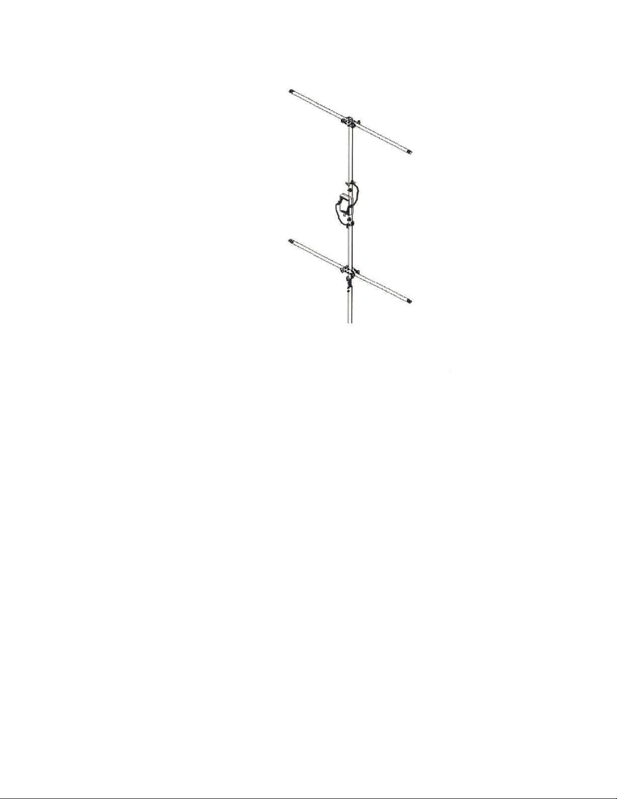
3) Assemble antenna. First, attach the bottom section to the middle section,
making sure to slide the pieces completely together. The ¼” holes in the middle
section should correspond completely with the holes in the bottom section, as
shown in step 1 below. Tighten the clamp knobs snugly. Next, loosen the wingnuts
on one side of the transformer, taking care not to lose the tiny washer. Attach the
ring connector, then the washer, then the wingnut, making sure to make good
contact, and tighten.
Second, attach the middle section to the top section as shown in step 2 below.
Again, the ¼” holes in the middle section should correspond with the holes in the
on the end of the top section. Tighten the clamp knobs snugly. Then, loosen the
wingnuts on the opposite side of the transformer, taking care not to lose the tiny
washer. Attach the ring connector, then the washer, then the wingnut, making sure
to make good contact, and tighten.
Finally, fold the arms of the top and bottom sections out as shown in step 3. The
arms should be folded out completely horizontal. Firmly tighten all four clamp
knobs to ensure that the top arms do not rotate downward over time.

Horizon Antennas UltraLite™
UltraLite™ Instruction Manual 10
Controller connection details

Horizon Antennas UltraLite™
UltraLite™ Instruction Manual 11
4) Install antenna onto the Permanent
Mounting Assembly. As shown at right,
slide the bottom of the bottom section into
the Permanent Mounting Assembly’s
insular tube, matching the holes. Slide
the clamp knobs through the holes and
firmly tighten.
4.3 Connections
Warning: Turn off equipment before making or removing any connections.
Failure to do so could result in equipment damage.
Ground connection. For reduced noise and RF exposure in your shack, all
equipment should be grounded to one common point on a water pipe or a copper
ground rod driven into the earth.
Feedlne. Connect at least a 65’ length of RG-
8 or RG-8X to the SO-239 port on the center
section on the bottom of the transformer.
Final connection notes: The coax cable
should feed the antenna at a 45-degree angle
as shown in the figure at right. Failure to do so
will result in parasitic coupling and will cause
higher than normal VSWR readings.

Horizon Antennas UltraLite™
UltraLite™ Instruction Manual 12
5. Adjustments
Danger: Do not apply RF power to the antenna while anyone is standing
near the antenna. RF burns or electrical shock may occur, causing severe injury
or death.
Equipment. The adjustment process requires Voltage Standing Wave Ratio
(VSWR) measurement. These measurements can be accomplished using most
any antenna analyzer. However, these devices typically generate a very small
signal (less than 0.2W) and may show higher than expected VSWR readings. A
reading of 1.5:1 at the tuned frequency is typical at this low power. The VSWR
readings should decrease once the antenna is used with 10W of power or more.
The VSWR reading on your transceiver will likely show a lower VSWR than a low-
power antenna analyzer.
Cables. Make sure that the coax used for the adjustment process is at least 65
feet long, and that the coax is installed at a 45-degree angle as described on page
11. Do not allow loops or coils in the cable, as this may create an RF choke. The
feedline neither radiates nor acts as a counterpoise for the antenna.
Avoiding Coupling. Due to parasitic coupling, installing your antenna on a
metallic stand may cause the tuned frequencies to differ from those of a permanent
installation. If a non-permanent mounting is required, we recommend our Horizon
non-metallic Quadrastand.
Operation Checklist: If adjustment proves difficult, follow this checklist to
eliminate common problems.
Is your antenna placed at least 30 feet away from other objects such as
buildings, people, trees, etc.? The ends of the antenna arms are very sensitive to
coupling with external objects.
Is your antenna installed such that the arms are at least 24 inches off the
ground? The spacing between the antenna’s lower arms and the ground should
be between 24 inches and 30 inches.
Is your coax cable a high-quality RG-8 or RG-8X cable?

Horizon Antennas UltraLite™
UltraLite™ Instruction Manual 13
Is your cable long enough? At least 65-feet of coax should be used for best
results.
Is your coax installed at a 45-degree angle with respect to the antenna as
pictured in the figure on page 11?
Are you checking the VSWR using at least ten watts? Once at least ten watts
is applied to the antenna, VSWR readings may improve significantly.

Horizon Antennas UltraLite™
UltraLite™ Instruction Manual 14
6. Accessories
Horizon UltraLite™ Stand
Four legged furniture-grade portable PVC stand
(22” tall, 41” x 41” footprint) Quick assembly and
disassembly. Fits in Travel bag.
Horizon UltraLite™ Travel Bag
Handy travel bag to carry your UltraLite
backpacking or on field day outings.

Horizon Antennas UltraLite™
UltraLite™ Instruction Manual 15
7. Contact Information
If you need to contact Horizon Antennas, just drop us an email at:
support@horizonantennas.net
Use this email address for help with installation, setup, adjustment, or operation,
for product or company information, or warranty/money back guarantee claims.
Check back at our website frequently for product updates at:
www.horizonantennas.net
We can also be reached through our web-based contact system on the website.
Table of contents
Other Horizon Fitness Antenna manuals
Popular Antenna manuals by other brands

MotoSAT
MotoSAT DataStorm D3 specification

Ubiquiti
Ubiquiti RocketDish RD-2G24 quick start guide

RCA
RCA ANT1560E quick start guide

Teletronics International
Teletronics International XI-1500 Configuration

ST Engineering Electronics
ST Engineering Electronics MDM2510 installation guide

Panorama Antennas
Panorama Antennas CM-36-55 Series Installation instruction