HORNE T105A Assembly instructions

Horne Engineering Ltd
Issue 7, November 2018 1
Horne Engineering Ltd
Po Box 7, Rankine Street
Johnstone, Renfrewshire
Scotland, PA5 8BD
Tel: 01505 321455
Fax: 01505 336287
Email: technical@horne.co.uk
Web: www.horne.co.uk
HORNE T105A/106A/107A/108A THERMOSTATIC SHOWER PANEL
FOR SURFACE MOUNTING WITH DUAL CONTROLS
INSTALLATION, OPERATING & MAINTENANCE INSTRUCTIONS
Note that these instructions feature the T108A shower panel. The T105A, T106A and T107A feature the
same TSV1-3 thermostatic valve but differ in the water outlet fittings. All comments relating to the T108A
also apply to the other shower panels mentioned above and their variants.
Approvals
The TSV1-3 Thermostatic Shower valve has been independently tested by WRc-NSF and approved to all
the requirements of NHS Model Engineering Specifications D08 Thermostatic Mixing Valves (Healthcare
Premises) to the following designations and for the following applications:
HP-S
Shower with supply pressures of 1 –5 bar and unrestricted flow rate
LP-SE
Shower with supply pressures of 0.2 –1 bar and unrestricted flow rate
Supply Water Pressure requirements
The minimum water pressure required to achieve a spray at the spray head is a dynamic head of 2m (3
psi, 0.2 bar) at the spray head. Note that for very low head installations, both hot and cold water supplies
must be at the same pressure.
Note that dynamic head is measured with the water running.
Where the TSV1-3 panel is fed by supplies with differing pressures, use the following to determine
whether a pressure-reducing valve (PRV) is required on the side with the higher pressure. Note that
output flow-rate is always determined by the lower of the two inlet pressures. If the lower inlet pressure is
low enough (typically 0.2 to 1Bar dynamic) that the flow-regulator in the outlet fitting (see pages 11,12,13)
can be removed, then a PRV should not be required. If the lower of the 2 supply pressures is higher than
around 1Bar, then a flow-regulator will be required to restrict flow. If the flow-regulator is needed, and the
supply pressures are substantially unbalanced, then a PRV will also be needed to prevent pulsing of the
flow. Although thermostatic performance is unaffected by this, the flow pulsing is undesirable.
High Pressure
Low Pressure
Maximum Static Pressure
10 bar
10 bar
Flow Pressure, Hot & Cold
1 to 5 bar
0.2 –1 bar
Hot Water Supply Temperature
52 –65C
52 –65C
Cold Water Supply Temperature
5 –20C
5 –20C
Minimum Temperature Differential
(Hot –Mixed, Mixed –Cold)
5K
(K = degrees C)
5K
(K = degrees C)
Temperature Adjustment Range
The mixed water temperature can be adjusted from cool through to a top limit (which can be preset during
installation –factory set to approx. 41°C - with full anti-scald protection throughout the range).
Water and Energy Conservation
The TSV1 range shower panels are fitted at the factory with flow regulators at the shower outlet to reduce
the flow rate and conserve water and energy. The drawings at the end of this document provide
information for accessing the flow restrictors/regulators for removal or replacement.

Horne Engineering Ltd
Issue 7, November 2018 2
Every HORNE TSV1-3 is supplied with an integral WRAS approved single check valve and integral large
surface area strainer. The Shower Panel terminates in 15mm copper pipes for hot and cold supplies. The
hot pipe is on the left, and cold on the right, when viewed from the user’s perspective.
INSTALLATION
The surface mounting enclosure is supplied with fixings to attach it to a wall. However consideration
should be given to the type of wall fittings required, as different substrates will require different fittings.
Recommended Mounting Heights
T105, T107, T108 Panels
Bottom of panel should be 1.0 metre from finished floor level.
T016 Panel (swivel-head, shown p13)
Bottom of panel should be 1.1 metres from finished floor level.
1) Position the Pre-Plumbed Enclosure
Identify a suitable position for the Enclosure and mark a line on the wall level with the top of the
casing. Mark a point on the wall which is on the required centreline for the Casing 15mm below
the line of the top of the casing for the support screw (See Fig 1).
2) Install the Support Screw
Drill a 7.0mm dia. hole in the wall and insert a wallplug and screw, leaving the head of the screw
11-13mm from the wall surface. Note that a stainless steel screw is supplied for this (corrosion
resistant).
3) Hang the Enclosure on the Support Screw
Release the top cover of the pre-plumbed enclosure by removing the four screws. Hang the pre-
plumbed enclosure on the support screw by the larger hole in the middle of the back strap and let
this take the weight of the enclosure. See Fig 2.

Horne Engineering Ltd
Issue 7, November 2018 3
Fig 1
Fig 2
4) Mark out the 4 Support Holes
Ensure that the enclosure is
hanging true and then mark out the
holes for the 2 upper support
screws. Remove the bottom cover
of the pre-plumbed enclosure and
mark out the 2 lower support
screws (See Fig 3).
5) Drill Support Holes
Carefully remove the pre-plumbed
enclosure from the temporary
support screw and, being careful
not to scratch the enclosure or its
covers, lay it down where it will not
be damaged. Drill the 4 holes and
install the wall plugs.
6) Attach the Pre-Plumbed Enclosure
to the Wall
Carefully re-hang the pre-plumbed
enclosure on the temporary screw.
Put the four supplied screw bushes
in the mounting holes in the panel
and then attach the panel firmly to
the wall by the four supplied
stainless steel screws. A bead of
silicon mastic can be used, if
required, to cover any gaps behind
the panel on uneven walls. Do not
mastic the lower End Cap to the
wall. See Fig 4.
Fig 3

Horne Engineering Ltd
Issue 7, November 2018 4
Fig 4. NB It is important to use the supplied screw bushes. Fig 5.
7) Connect the Supply Pipes
N.B. Ensure that the top cover of the pre-plumbed enclosure is replaced prior to connecting up the
supply pipes. The fitting of isolation valves is required as close as practicable to the water supplies
inlets of the shower panel.
Connect the hot water supply to the left hand inlet, and cold water to the right-hand inlet (See Fig 5).
DO NOT OPEN THE WATER SUPPLIES AT THIS STAGE AS THEY HAVE NOT BEEN FLUSHED
OUT TO REMOVE THE DEBRIS IN THE PIPEWORK. SUCH DEBRIS CAN DAMAGE THE
THERMOSTATIC VALVE.
8) Flush the Pipework
Flush out the pipework in accordance with Water Bylaws 2000 (Scotland) and BS 6700: 1997
(England & Wales). The use of a Horne flushing kit is strongly recommended, because this
connects directly to the water inlets to the mixing valve. Access to the flushing points is gained
from underneath the casing through the lower end cap. Isolate the water supplies and also the
low level servicing valves located on the side of the panel (see Fig 6) using the supplied 4mm hex
key. Remove the strainer cap with the strainer basket and screw in the flushing adapter. Place
the end of the flushing hose in an appropriate drain or container and turn on the supply to flush as
required. After flushing, remove the flushing adapter and replace the strainer cap. Repeat for
both hot and cold supplies. See Figs 6 and 7.
NOTE THAT IF THERE IS ANY DANGER OF FREEZING THEN THE PIPES AND TSV1-3 MUST
BE DRAINED TO AVOID DAMAGE.

Horne Engineering Ltd
Issue 7, November 2018 5
Fig 6.
Fig 7.
9) Test for Leaks in Pipework
Ensure that the TSV1-3 on/off control is closed (i.e. turned fully clockwise) and open the supplies.
Open the servicing valves on the TSV1 Casing (See Fig 6). Turn on the supplies and adjust the
temperature control and check for any water leaks upstream of the TSV1-3 valve. Make good any
leaks found. The valve is now ready for commissioning.
Note that if the controls, enclosure and shower accessories require cleaning then care must be taken
not the scratch them in the process. Wash off any surface dust with the shower spray before
cleaning with soapy water.
DO NOT USE ANY ABRASIVE CLEANERS OR SOLVENTS OR THE SURFACES MAY BE
DAMAGED.
Backflow Prevention
The hot and cold inlets to the TSV1-3 valve are fitted with single in-line WRAS Approved DN15 Check
Valves.
Supplementary Installation Instructions for T10XB Variants.
TSV1 Panel Mounted Shower Valves are available in versions with flexible braided stainless steel inlet
hoses rather than top entry isolating valves. The hoses used are PEX (cross-linked polyethylene). They
are not EPDM lined. These versions have Product Reference codes with the suffix B, e.g. T108B.
The main difference, from an installation point of view, is that the water supplies may have to be
connected before the pre-plumbed enclosure is attached to the wall.
Accordingly, point 7 on the attached installation instructions (Connect the Supply Pipes) should be
performed before point 6 (Attach the Pre-Plumbed Enclosure to the Wall) unless alternative access is
available to the connections, e.g. via an access panel.
Note that the braided hose inlets are colour coded with BLUE for the Cold Water Supply and RED for the
Hot Water Supply.
Care should be taken to ensure that the weight of the pre-plumbed enclosure is taken by the mounting
screws and NOT by the hoses.
COMMISSIONING
It is essential to commission the valve in order to establish a reference point for future in-service tests.
Ensure that the pipework has been flushed out before commissioning the TSV1-3. (See installation
instructions.)
Ensure that the NHS designation of the valve matches the intended application, that both hot and cold
water supplies are open and at, or near, their design temperatures and pressures and that they are within
the requirements of the valve as outlined on page 1, and within guidance information on the prevention of
legionella, etc. NB Ensure that the servicing valves are also open (see Para 8).
Set the temperature control to the maximum temperature setting (i.e. rotate the control anticlockwise until
it stops).
Fully open the on/off control by turning it anticlockwise. For installations with a fixed shower head, putting
a burst polythene bag over the shower head will help to catch and deflect the spray during commissioning.

Horne Engineering Ltd
Issue 7, November 2018 6
Allow the shower to run at maximum temperature setting until the water temperature has stabilised.
Should the temperature rise, or drop, in an uncontrolled fashion, then
the hot and cold supplies are probably reversed. Correct this before
proceeding.
The TSV1-3 is set in the factory to provide a maximum outlet
temperature of approximately 41°C, but this should be checked on site
to ensure that the setting has not been altered, and to ensure user
safety. If necessary, reset the maximum outlet temperature to 41°C.
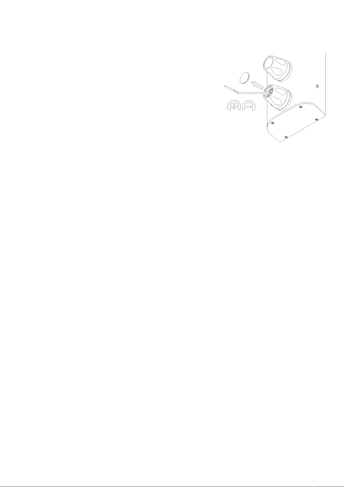
If the maximum temperature requires adjustment, remove the
temperature control cap using a small plastic spudger or blade and
adjust the small slotted screw in the centre of the spindle. Adjust the
screw anticlockwise to increase the temperature, clockwise to
decrease the temperature. See Fig 8.
Fig 8
After setting the maximum temperature, turn the shower on and off a few times and check that the
maximum setting is correct. Note that the final stabilised Mixed Water Temperature should not exceed 43C
to comply with DO8. Record the commissioning information, including equipment used, on the attached
commissioning sheet to permit the in-service performance of the valve to be assessed at a later date.
Finally, check the thermal shut-off facility of the TSV1-3 by performing a thermal shut off test (often called
a cold fail test). With the shower running, close the cold (i.e. right hand) servicing valve. The Servicing
Valve is closed when the arrows are in the horizontal position, and open when they are in the vertical
position. See Fig 6. The flow from the shower head should immediately stop or reduce to a trickle, in
which case the mixed water temperature rise should be less than 2°C above the set temperature. In either
case, there is no scalding risk. If the temperature rises above this then it is likely that there is
contamination in the TSV1-3 that is preventing it from shutting off the hot supply. Restore the supply and
note the final stabilised temperature, which should not exceed 43°C.
Refer to the maintenance section of this booklet or phone the factory for advice, if necessary.
MAINTENANCE
Maintenance of the TSV1-3 shower valve is essential to ensure the product continues to perform to
specification after installation, and continues to afford scald protection. Record all maintenance carried out
on the attached commissioning and maintenance record.
When cleaning the external faceplates and knobs, never use cleaners containing abrasives or solvents as
they may damage the chrome plating. Use only a soft cloth and soap.
The frequency of routine maintenance of the TSV1-3 internals (i.e. cleaning, descaling etc) depends
largely on the condition of the water supplies, and local knowledge will dictate suitable intervals. In
addition to this the following precautions should be observed.
Initially check the strainer baskets for debris every three months and clean if required. This period can be
increased if appropriate once the general condition and cleanliness of the water is established.
Perform a thermal shut-off test every three months, and check the maximum temperature setting. See the
last paragraph in the Commissioning Instructions for details of the thermal shut-off test and re-adjustment
of the maximum temperature setting, if required.
If the maximum water temperature rises by more than 2K (2°C) from the commissioned setting then
ensure that the strainers are clean and that the isolating valves are fully open. Test the Check Valves as
described below. If these tests do not highlight the reason for the temperature rise then follow the
procedure below for investigating failure of the thermal shut-off test.

Horne Engineering Ltd
Issue 7, November 2018 7
If the TSV1-3 fails the thermal shut of test then remove the temperature control knob and the thermostatic
cover (see Installation section for details) and check the internal surfaces for scaling. If the TSV1-3 body
requires descaling then it should be removed from the casing to do this. All rubber parts must be removed
prior to descaling. Do not forget the Slide Valve Seal located inside the TSV1-3 body, which should
always be replaced with a new seal after removal. Maintenance kits are available which contain “O” rings
and/or the Thermostatic Element. Smear all “O” rings with silicon oil prior to installing them. Torque the
TSV1-3 cover to 40 Nm (54 lbft). This is to prevent the user from inadvertently unscrewing the cover
during temperature adjustment. Do not over tighten the cover.
Replace the “O” rings every three years (Maintenance kit with spare “O” rings available). Smear silicon oil
on all “O” rings prior to installation. Lightly smear the outside diameter of the slide valve with silicon oil
prior to installation.
Replace the Thermostat Element and slide valve assembly at least once every 6 years in all TSV1-3
valves, or more often if problems are experienced or in installations where the water is aggressive.
The On/Off mechanism uses a ½” washer, which should be replaced when it leaks. Remove the cosmetic
trim and unscrew the on/off assembly. The washer is retained by a small nut. Do not over tighten this nut
(torque to 2.5 Nm). Ensure the on/off assembly is torqued down to 25 Nm (34 lbft) to prevent the user
from inadvertently unscrewing the assembly during flow control. Do not over tighten the assembly.
The Check Valves prevent crossflow between hot and cold water supplies under unequal pressure
conditions, and are designed for long life with no maintenance. Their function can be tested as follows:
To test the Check Valve on the hot side, shut off the hot supply and ensure the cold supply is open. Be
prepared for leakage of trapped water from the pipe and remove the strainer basket on the hot side. Any
continuing leakage evident from the strainer body is likely to be coming through the hot supply Check
Valve (N.B. Ensure the hot isolating valve shuts off tightly, or it may cause leakage here).
To test the Check Valve on the cold side, shut off the cold supply and ensure the hot supply is open. Be
prepared for leakage of trapped water from the pipe and remove the strainer basket on the cold side. Any
continuing leakage evident from the strainer body is likely to be coming through the cold supply Check
Valve (N.B. Ensure the cold isolating valve shuts off tight, or it may cause leakage here).
If either Check Valve is leaking then the inlet elbow (complete with Check Valve and strainer basket)
should be replaced. It is not possible to satisfactorily remove the Check Valve itself from the inlet elbow
and this should not be attempted. The shower valve body must be removed from the pre-plumbed
enclosure in order to remove the inlet elbows. See Fig 9 for the location of the parts.
Care should be taken not to lose any of the parts from the drive coupling on the Servicing Valves.
Fig 9.

Horne Engineering Ltd
Issue 7, November 2018 8
To remove the spray plates from the fixed shower head, rotate the lock rings to 30 degrees anticlockwise
to release the bayonet fitting and then ease out the spray plates by the lock ring. Note that for the fixed
showerhead, a tool is supplied with the showerhead to engage the lock ring as shown in Fig 10.
Fig 10.
See attached drawings 8341 and 8342 for parts lists for ordering spares.
IN-SERVICE TESTING
Periodic testing should be carried out to check whether or not any deterioration has occurred in the
performance of the TSV1-3. The results of these tests, and the equipment used, should be recorded on
the Commissioning, Maintenance and In-Service Testing Sheet at the back of these instructions. Fill in all
the parameters requested on the sheet.
Note that instrumentation to the same specification should be used each time when measurements are
taken to ensure consistency of results. Record all the information on the In-Service Testing sheet at the
back of these instructions.
A thermal shut-off test, as described under “Maintenance”above, should be carried out. Ensure that the
servicing valves are fully opened (see Fig 6) before performing this test. If mixed water continues to flow
and is coming from the showerhead at a temperature of more than 2°C above the maximum mixed water
temperature setting then the TSV1-3 is due for maintenance. Any requirement to adjust the Mixed Water
Temperature should be recorded, and the strainers checked for cleanliness, and check valves checked.
Note: A thermostatic mixing valve in need of maintenance can be undetectable in normal use and
only become apparent when disruption occurs in the hot or cold water supply temperatures or
pressures. In service testing should be carried out at a frequency to detect any such deterioration.
The frequency of in-service testing depends upon the condition of the water passing through the TSV1-3.
In-service testing must be carried out more frequently in hard water areas than in soft water areas. As a
general guide, in-service testing should be carried out at intervals somewhere between 6 months and 12
months. In-service testing should be carried out at least every 12 months and, where the water is hard,
the interval may be less than 6 months. Experience of local conditions and the in-service testing record
will dictate the frequency of in-service testing. In the absence of practical experience of this, a first check
6 –8 weeks after commissioning should be performed. If no problems are detected (and mixed water temp

Horne Engineering Ltd
Issue 7, November 2018 9
is within 1C of the commissioning temp) then checking again 12 –15 weeks after commissioning will help
to build up a history. The results should be recorded on the attached sheet. Any requirement to reset the
mixed water temperature should be noted. If no such adjustments are required, then the next in-service
tests can be scheduled for 24 –28 weeks after commissioning. If small adjustments (1 to 2 K) are required
then check the strainers for cleanliness, make sure the isolating valves are fully open and verify the check
valves are operating correctly (see Maintenance Section). The next in-service test should be conducted 18
- 21 weeks after commissioning. If larger adjustments are required (>2K), then service work is required
and the in-service tests should be repeated 18 –21 weeks after commissioning. Note that the pressure
and temperatures of the supplies must be identical to those during commissioning for the in-service tests
to be meaningful.

Horne Engineering Ltd
Issue 7, November 2018 10

Horne Engineering Ltd
Issue 7, November 2018 11

Horne Engineering Ltd
Issue 7, November 2018 12

Horne Engineering Ltd
Issue 7, November 2018 13

Horne Engineering Ltd
Issue 7, November 2018 14
COMMISSIONING, MAINTENANCE & IN-SERVICE TESTING RECORD
Establishment:
Type of Valve: Horne TSV1-3 Shower Valve
Date Installed:
Installed by:
Location of Valve:
Commissioning Details Note: Fill in ALL information during commissioning.
Hot Water Supply :
HW Temp C
HW Pressure
Bar
Temp:
Instrumentation:
Pressure:
Cold Water Supply:
CW Temp C
CW Pressure
Bar
Mixed Temp at max draw-off:
Mixed Temp: C
Flowrate at max draw-off: l/min
Mixed Temp at low draw-off:
Mixed Temp: C
Flowrate at low draw-off: l/min
Instrumentation Used:
Temp:
Press:
Flow:
Cold Water Isolation Test
Max Mixed Water Temp during CW Isolation test: C Mixed Water Temp on restoration of CW Supply: C
Note: MWT should return within 2 degrees of set temp, and be no greater than 43C after this test.
Comments:
In-Service Testing Record
Date:
Hot Water Supply :
HW Temp C
HW Pressure
Bar
Temp:
Instrumentation:
Pressure:
Cold Water Supply:
CW Temp C
CW Pressure
Bar
Mixed Temp at max draw-off:
Mixed Temp: C
Flowrate at max draw-off: l/min
Mixed Temp at low draw-off:
Mixed Temp: C
Flowrate at low draw-off: l/min
Instrumentation Used:
Temp:
Press:
Flow:
Cold Water Isolation Test
Max Mixed Water Temp during CW Isolation test: C Mixed Water Temp on restoration of CW Supply: C
Note: MWT should return within 2 degrees of set temp, and be no greater than 43C after this test.
Comments:
Recommended Date of Next In-Service Test:

Horne Engineering Ltd
Issue 7, November 2018 15
IN-SERVICE TESTING RECORD
(Note: Photocopy this page)
In-Service Testing Record Establishment: Location of Valve:
Date: Type of Valve : TSV1-3 Shower Valve
Hot Water Supply :
HW Temp C
HW Pressure
Bar
Temp:
Instrumentation:
Pressure:
Cold Water Supply:
CW Temp C
CW Pressure
Bar
Mixed Temp at max draw-off:
Mixed Temp: C
Flowrate at max draw-off: l/min
Mixed Temp at low draw-off:
Mixed Temp: C
Flowrate at low draw-off: l/min
Instrumentation Used:
Temp:
Press:
Flow:
Cold Water Isolation Test
Max Mixed Water Temp during CW Isolation test: C Mixed Water Temp on restoration of CW Supply: C
Note: MWT should return within 2 degrees of set temp, and be no greater than 43C after this test.
Comments:
Recommended Date of Next In-Service Test:

Horne Engineering Ltd
Issue 7, November 2018 16
Brochure Ref: L-189 (T10XA)
Horne Engineering Ltd
PO Box 7
Rankine Street
Johnstone
SCOTLAND
PA5 8BD
Tel: +44 (0)1505 321455
Fax: +44(0)1505 336287
Email: Technical@horne.co.uk
www.horne.co.uk
This manual suits for next models
3
Table of contents
Popular Plumbing Product manuals by other brands

ESS
ESS Easy Drain Multi TAF EDMTAF2000 Installation advice

Moen
Moen Vivid TS888 series Specifications

Kohler
Kohler K-13142 Homeowner's guide

Graff
Graff GN-6836-LM47W Series installation instructions

Hans Grohe
Hans Grohe PuraVida 15074 Series Instructions for use/assembly instructions

WimTec
WimTec SanTec PROOF Installation and operating instructions