EN - 9
English
3GENERAL INFORMATION
3.1 Use of the manual
This manual forms an integral part of the appliance and should be
kept for future reference. Please read it carefully before installing/
using the unit If the appliance is sold, the Seller must pass on this
manual to the new owner along with the appliance.
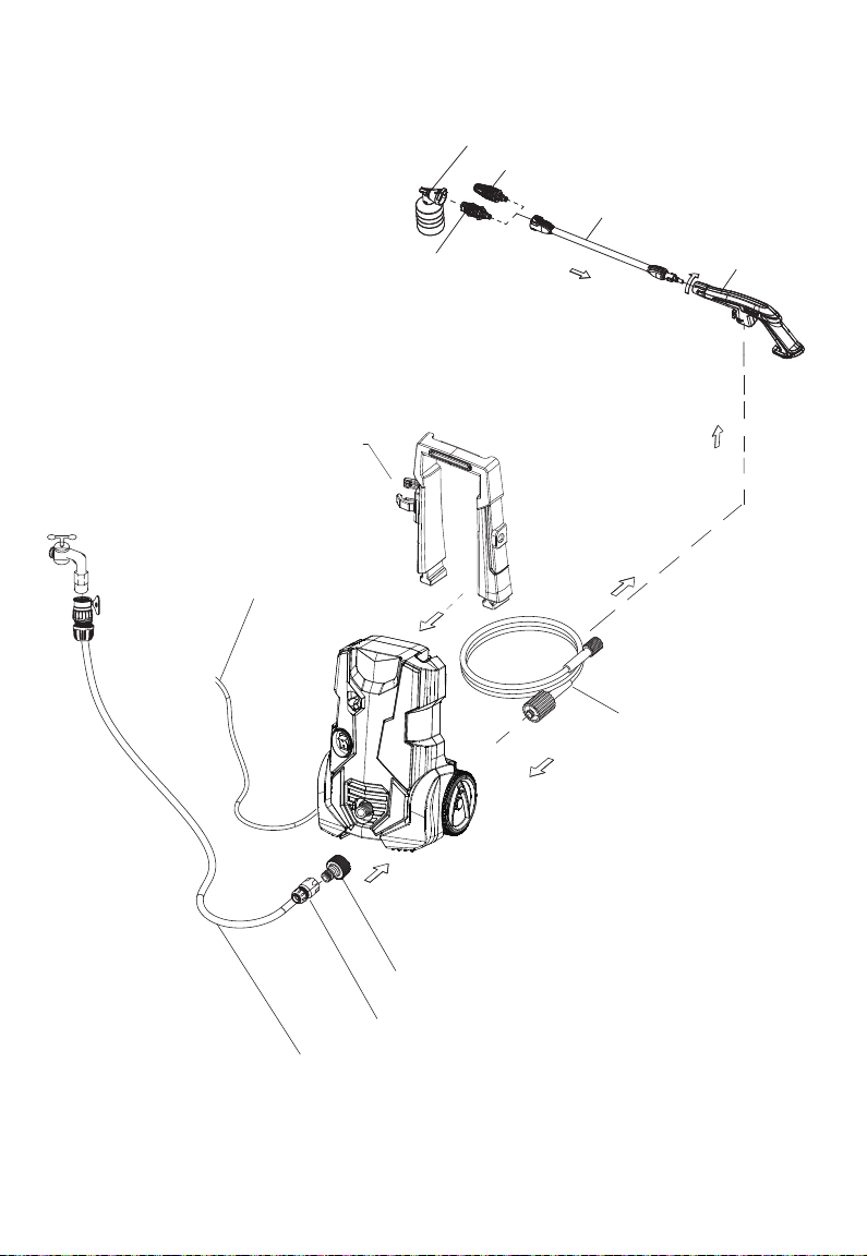
3.2 Delivery
The appliance is delivered partially assembled in a cardboard box.
The supply package is illustrated in g.1.
3.2.1 Documentation supplied with the appliance
A1 Use and maintenance manual
A2 Safety instructions
A3 Declaration of conformity
A4 Warranty regulations
3.3 Disposing of packaging
The packaging materials are not environmental pollutants but must
still be recycled or disposed of in compliance with the relevant
legislation in the country of use.
3.4 Safety signs
Comply with the instructions provided by the safety signs tted to
the appliance.
Check that they are present and legible; otherwise, t replacements
in the original positions.
E1 sign - Indicates that the appliance must not be disposed of as
municipal waste; it may be handed in to the dealer on purchase of a
new appliance. The appliance’s electrical and electronic parts must
not be reused for improper uses since they contain substances
which constitute health hazards.
3.4.1 Symbols
E2 symbol - Indicates that the appliance
is intended for professional use, i.e. for
experienced people informed about the relative
technical, regulatory and legislative aspects and capable
of performing the operations necessary for the use and
maintenance of the appliance.
E3 symbol - Indicates that the appliance is
intended for non-professional (domestic) use.
4TECHNICAL INFORMATION (see data plate)
4.1 Envisaged use
This appliance has been designed for individual use for the cleaning
of vehicles, machines, boats, masonry, etc, to remove stubborn dirt
using clean water and biodegradable chemical detergents.
Vehicle engines may be washed only if the dirty water is disposed
of as per regulations in force.
- Intake water temperature: MAX 40°C
- Intake water pressure: min. 0,1 MPa-max 1MPa.
- Operating ambient temperature: above 0°C.
The appliance is compliant with the EN 60335-2-79/A1 standard.
4.2 Operator
The symbol on the front cover identies the appliance’s intended
operator (professional or non-professional).
4.3 Improper use
Use by unskilled persons or those who have not read and
understood the instructions in the manual is forbidden.
The introduction of inammable, explosive and toxic liquids into the
appliance is prohibited.
Use of the appliance in a potentially inammable or explosive
atmosphere is forbidden.
The use of non-original spare parts and any other spare parts not
specically intended for the model in question is prohibited.
All modications to the appliance are prohibited. Any modications
made to the appliance shall render the Declaration of Conformity
null and void and relieve the manufacturer of all liability under civil
and criminal law.
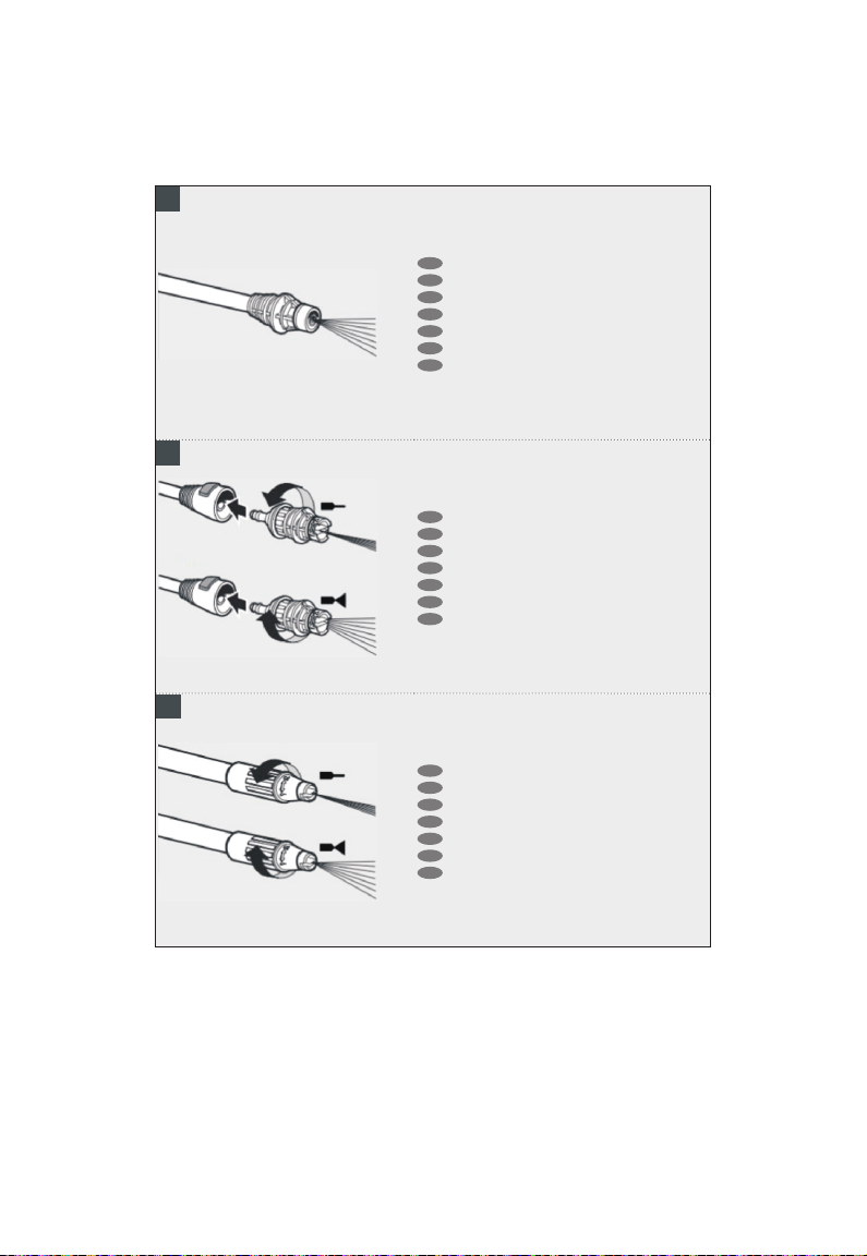
4.4 Main components
B1 Adjustable spray nozzle
B2 Lance
B3 Gun with safety catch
B4 Power supply cable with plug
B5 High pressure hose
B6 Detergent tank (on models with this feature)
4.5 Safety devices
Caution - Danger!
Do not tamper with or adjust the safety valve setting.
- Safety valve and/or pressure limiting valve.
The safety valve is also a pressure limiting valve.
When the gun trigger is released, the valve opens and the water
recirculates through the pump inlet or is discharged onto the
ground.
- Thermostat valve (D1 where tted)
If the water temperature exceeds the temperature set by the
manufacturer, the thermostat valve discharges the hot water and
draws in an amount of cold water equal to the amount of water
discharged, until the correct temperature is restored.
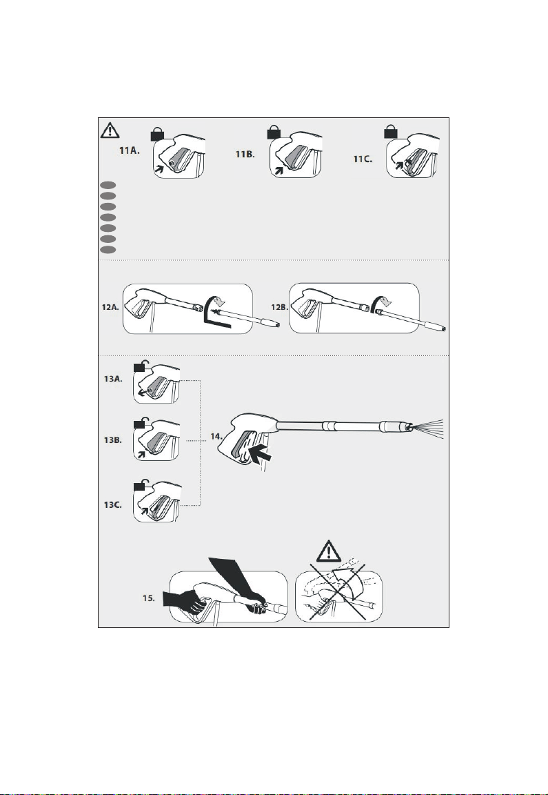
- Safety catch (D): prevents accidental spraying of water.
5INSTALLATION (FIG.2) (A-B-C-D)
5.1 Assembly
Caution - Danger!
All installation and assembly operations must be
performed with the appliance disconnected from the
mains power supply.
The assembly sequence is illustrated in g.1
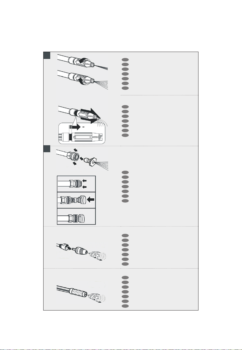
5.2 Assembling the rotating nozzle
(For models with this feature)
The rotating nozzle kit delivers greater washing power.
Use of the rotating nozzle may cause of reduction in pressure of
25% compared to the pressure obtained with the adjustable nozzle.
However, the rotating nozzle kit delivers greater washing power due
to the rotation of the water jet.
5.3 Electrical connection
Caution - Danger!
Check that the electrical supply voltage and frequency
(V-Hz) correspond to those specied on the appliance
data plate. The appliance should only be connected to a mains
power supply equipped with an adequate earth connection and
a differential security breaker (30 mA) to cut off the electricity
supply in the instance of a short circuit.
5.3.1 Use of extension cables
Use cables featuring “IPX5” protection level.
The cross-section of the extension cable should be
proportionate to its length; the longer it is, the greater its
cross-section should be. See table I.
5.4 Water supply connection
Caution - Danger!
Only clean or ltered water should be used for intake.
The delivery of the water intake tap should be equal to
that of pump capacity.
Place the appliance as close to the water supply system as
possible.
5.4.1 Connection points
Water outlet (OUTLET)
Water inlet with lter (INLET)