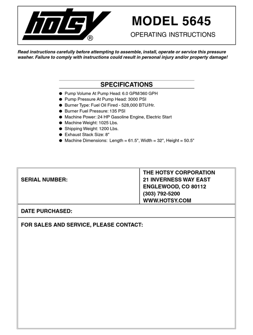
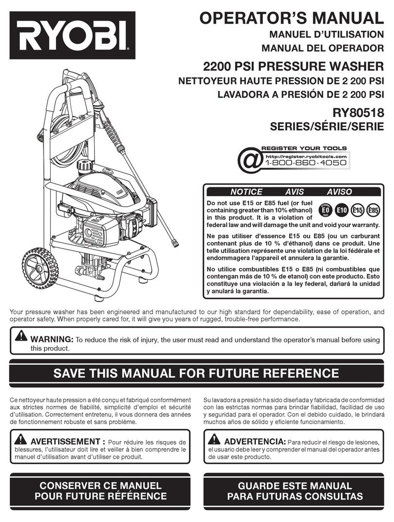
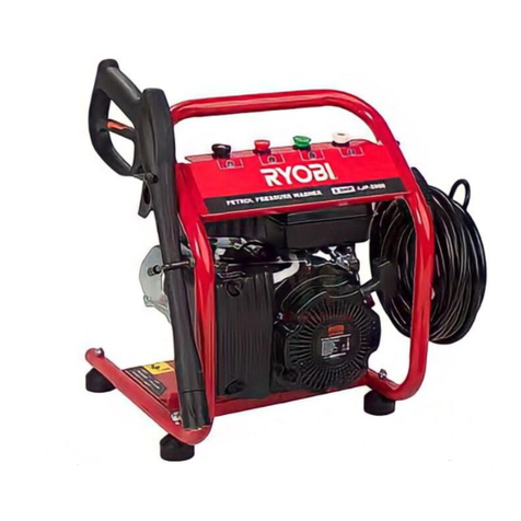
Ryobi AJP-1622 Operation manual

6987309-00 STD( ナンア )
01-16
AJP-1622
Original instruction

1
1
4
2
10
5
9
8
1
8
2
5
4
3
6
7
9 10 11
7
6
12
17
Original instruction

2
10
5
2
4
9
5
5
2
4
6, 7
22
2 3 4
5 6
98
10 11
7
9
5
8
6, 7
4
Original instruction

3
12
14
16
17
15
13
90°
2
13
14 14
13
6
6
A
AB
B
7
3
3
2
2
OFF
O
eco Normal
12
Original instruction

4
18 19
20
6
10
16
15
8
6
72
17
4
Original instruction

5
Carefully read and understand these instructions
before operating this high pressure washer.
Package Contents (Fig.1)
1. Main unit
2. Spray handle
3. Foam nozzle
4. Spray handle hose (6m)
5. Water supply hose (3m)
6. Variable nozzle lance
7. Turbo nozzle lance
8. Water connector (Main unit attachment)
9. Hose joint
10. Hose clamp
11. Nozzle cleaning pin
Technical data
Power rating input 1,900 W
Rated pressure Normal mode 8 MPa
Eco mode 5.5 MPa
Allowable pressure 12 MPa
Rated ow Normal mode 6.0 L / min
Eco mode 4.5 L / min
Max. inlet water pressure 0.6 MPa
Max. temperature: 40℃
Adding water From a faucet
Weight 6.5 Kg
Sound pressure level LpA=72.7dB(A)
Sound power level LwA=85.7dB(A)
Vibration Value aH=2.5m/s2
Name of Parts:
1. Main unit
2. Spray handle
3. Foam nozzle
4. Spray handle hose (6m)
5. Water supply hose (3m)
6. Variable nozzle lance
7. Turbo nozzle lance
8. Water connector
9. Hose joint
10. Hose clamp
11. Nozzle cleaning pin
12. Main switch
13. Safety lock button
14. trigger
15.Filter
16. Rubber washer
17. Power cord
Preparation
Before starting up your machine, we advise you to carefully
read through this instruction manual. Follow all instructions
to minimize the risk of injuries when using the machine.
Prior to operation
Before starting up your machine, please check it carefully for
any defects. If you nd any, do not start up your machine and
contact your distributor.
Especially check:
The insulation of the electric cable should be faultless and
without any cracks. If the electric cable is damaged, it should
be replaced by RYOBI authorized distributor.
Mains power supply connection
The following should be observed when connecting the
machine to the electric installation:
• Check before operation that the local power supply is the
same as the specications on the rating label.
• This machine is equipped with universal motor with double
insulation. It is not necessary to have earth connection.
• The electric installation shall be made by a certified
electrician.
• It is strongly recommended that the power supply to the
machine should include a residual current device (RCD).
• Product protection degree:IPX5
General safety regulations and accident
prevention
It is essential that you read the safety regulations and
operating instructions in their entirety and follow the
information contained therein in order to eliminate the
possibility of an accident or potentially dangerous situation
from occurring while working with the machine.
• The power plug must be plugged into a properly installed
socket. The power supply should include a residual
current device for max. 30 mA.
• Always check the device, the mains cable and the plug
before using the machine. Only operate the device when
it is in good working order and has not been damaged in
any way. Damaged parts must be immediately replaced
by a qualied electrician.
• Always pull the power plug out of the socket outlet before
doing any work on the machine, before changing the
nozzle and whenever it is not being used.
• Warning! Inadequate extension cords can be dangerous.
• If an extension cord is used, it shall be suitable for outdoor
use, and the connection has to be kept dry.
• Only use suitable extension cable when working outdoors.
Extension cable must have a minimum cross-section of
1.5 mm2.
• Warning! This device was developed to be used with
cleaning agents supplied or recommended by the
manufacturer. The use of any other cleaning agents or
chemicals can negatively affect the safety of the device.
• Cable connections should be kept dry and off the ground.
Always uncoil the extension cable completely to avoid
heat damage to the cable.
• Warning! Do not use the device when other persons or
animals are in the near vicinity unless they are wearing
appropriate protective clothing.
• Warning! High pressure jets can be dangerous when the
machine is not use properly. Do not direct the jet toward
persons, animals, live electrical equipment or the device itself.
• Do not direct the jet against yourself or others in order to
clean clothes and footwear.
• Children should be supervised to ensure that they do not
play with the machine.
• This machine is not intended for use by persons (including
children) with reduced physical, sensory or mental capa-
bilities, or lack of experience and knowledge, “High pres-
sure cleaners shall not be used by children or untrained
personnel.”
• Warning! Spray handle hoses, ttings and couplings are
important components for the safety of the device. Only
use spray handle hoses, fittings and couplings that are
recommended by the manufacturer.
Original instruction

6
• In order to ensure the operational safety of the device,
only use genuine manufacturer’s replacement parts or
parts that have been approved by the manufacturer.
• Do not operate the device if the mains cable or other
important parts of device – e.g. safety related elements,
spray handle hose, spray pistol – are damaged.
• Do not pull or carry the electric tool by its mains cable.
Protect the mains cable from becoming damaged by oil,
solvents and sharp edges.
• Keep your place of work tidy.
• Ensure that the switch is turned off when connecting the
machine to the power supply.
• Wear the suitable work clothes.
• Check your machine to ensure that it is in good working
order. If it is not functioning properly, have it checked by
an RYOBI authorized distributor. Have all maintenance
and inspection work carried out only by RYOBI authorized
distributor.
• The water jet that emerges from the high pressure nozzle
produces a ‘kickback’ on the spray handle. Therefore,
make sure that you have a solid footing and that you have
a rm hold of the handle grip. In order to protect yourself
from possible ying objects (that are released due to the
high pressure).
• The high pressure jet can damage vehicle tyres and tyre
parts. Keep a distance of at least 30 cm from the object
being cleaned.
• If there is a power failure while you are using the machine,
be sure to switch off the machine for safety reasons.
• The electric pump always must be able to draw on a
sufficient supply of water. Dry operation causes severe
damage to the seals.
• Disconnect from the power supply before carrying out
user maintenance.
• Only use genuine spare parts from the manufacturer or
approved by the manufacturer.
• If the supply cord is damaged, it must be replaced by
RYOBI authorized distributor in order to avoid a hazard.
• Never use the machine in an environment where there
could be a danger of explosion. If any doubt arises, please
contact RYOBI authorized distributor.
• It is not allowed to clean asbestos-containing surfaces
with high pressure.
• This machine must not be used at temperatures below
0℃.
• The electric supply connection (for example, connection
the RCD or x wiring) shall be made by a qualied electri-
cian and comply with IEC60364-1: Low-voltage electrical
installations.
Safety devices
Safety lock on spray handle
The spray handle features safety lock button (13). When the
lock is activated, the spray handle cannot be operated.
Motor pump protection
The motor is equipped with a motor circuit breaker switch.
When the motor starts to run hot, it is cut out automatically
by this switch. Switch off the machine. Wait 5 ~ 10 minutes
before using the device again. Try to determine the cause of
the fault. If the problem repeats itself, please contact RYOBI
service centre.
Using cleaning agent
Fill detergent tank with an appropriate cleaning agent, and
the connect the foam nozzle to the spray handle.
Operating instructions
Purpose
The machine is designed to clean vehicles, machines, build-
ings, facades, etc. in the private sector.
Areas of application
• Never use the machine in potentially explosive areas
under any circumstances!
• The operating temperature must be between 0℃ and +40
℃.
• The machine consists of an assembly with a pump, which
is encased in a shock absorbing housing. For an optimal
working position the machine comes with a lance and
a non-slip handle grip, whose shape and configuration
comply with the applicable regulations.
• Do not cover or modify the lance or the spray nozzles in
any way.
• The machine is designed to be used with cold orThe machine is designed to be used with cold or
lukewarm (max. 40℃); higher temperatures can damage
the pump.
• Do not use water that is dirty, gritty or contains anyDo not use water that is dirty, gritty or contains any
chemical products, as these could impair operation and
shorten the life of the machine.
Assembly
※ Tools needed for assembly: Phillips screwdriver, 17mm
wrench
1. Attach the water supply hose to the faucet (Fig. 2)
WARNING! Remove dirt and debris from the faucet and
from the outside and inside of the hose.
Allow the water from the faucet to run for a short time
before attaching the hose.
Dirt or debris entering the unit may cause damage to the
pump.
WARNING! Be sure to use water directly from the water
faucet. Hot water (over 40℃) and water from hot springs
may damage the unit.
Attach the water supply hose (5) to the water faucet with
the hose clamp (10).
Tighten the clamp screw to secure the hose to the faucet.
2. Attaching the hose joint to the water supply hose
(Fig.3,4,5)
Loosen and remove the hose link from the hose joint (9).
Insert the water supply hose (5) through the hose link.
Insert the end of the water supply hose securely into the
connecting portion of the hose joint.
Securely tighten the hose link onto the hose joint by
turning the hose link clockwise.
WARNING! There is a valve attached to the hose joint.
Water will not ow out of the hose until it is attached to
the water connector.
3. Connecting the hose joint to the water connector (Fig.6)
Push the hose joint (9) onto the water connector (8) until
you hear a 'click' sound.
WARNING! Jiggling the water supply hose to the right
or left when attaching may cause water to leak from the
connection area.
Original instruction

7
4. Connecting the spray handle hose to the spray handle
(Fig.7,8)
Connect the spray handle hose (4) to the spray handle
(2) by rotating the hose coupling. Tighten with a 17mm
wrench.
WARNING! Water leakage may occur if the hose is not
secured properly or if the connectors are not free from
dirt and debris prior to connecting.
5. Connecting the spray handle hose to the water discharge
nozzle (Fig.9)
Secure the spray handle hose (4) directly onto the water
discharge nozzle and turn the hose link clockwise to
connect.
Turn the hose link until it is secure.
WARNING! Jiggling the spray handle hose to the right or
left when connecting, may cause water to leak from the
connection area.
6. Connecting the nozzle to the spray handle (Fig.10,11)
Insert the nozzle (6 or 7) so that it ts securely into the
slotted spray handle and turn the hose nozzle clockwise
while pushing rmly.
Test the connection by pulling on the nozzle.
Operating the Switch (Fig.12)
Turning the main switch (12) to the "eco" or "Normal"
position starts the unit. Returning the switch to the "OFF"
position cuts electrical power to the unit.
Using the the Spray Handle (Fig.13)
Pulling the spray handle trigger (14) releases a highly
pressurized water ow. Releasing the trigger stops the ow.
The spray handle safety lock button (13) prevents accidental
operation.
When locked, the trigger cannot be depressed.
Lock the trigger by pushing the safety lock button in from the
right side (Figure A). Release the lock by pushing the button
from the opposite direction (Figure B).
Changing the Spray Direction (Fig.14)
The spray handle neck rotates 90 degrees.
The spray direction of the variable nozzle lance (6) can be
changed during operation.
WARNING! After attached the nozzle, test the connection
by pulling on the nozzle. Pushing on the nozzle while turning
will detach the variable nozzle lance from the spray handle.
Variable Nozzle Lance (Fig. 15)
Changing the spray diffusion (narrow ⇔wide)
Change the spray diffusion by turning the end of the variable
nozzle lance clockwise for narrow spray diffusion and
counterclockwise for wide spray diffusion.
Narrow spray … Water is sprayed in a concentrated direct
ow. The narrow spray setting is useful for
removing stubborn grime.
Wide Spray …… Water is sprayed in a widely diffused
flow. The wide spray setting is useful for
removing dirt from large areas, washing
cars, etc.
Turbo Nozzle Lance (Fig. 16)
The turbo nozzle lance (7) increases washing efciency with
a rotating spray.
WARNING! The turbo nozzle lance uses the narrow spray
setting only.
The turbo nozzle lance emits a forceful spray that is not
suitable for use on fragile items, items susceptible to surface
peeling, or for washing cars.
Attaching the Foam Nozzle (Fig.17)
1. Fill the foam nozzle container with manufacturer
recommended detergent.
2. Insert the foam nozzle (3) so that it ts securely into the
slotted spray handle.
3. Insert the foam nozzle completely into the spray handle
and turn the spray handle clockwise until it stops.
4. Test the connection by pulling on the foam nozzle. Keep
hands clear of the nozzle when testing the connection.
Use the foam nozzle in the position shown in Figure 17.
Operating the Unit
1. Ensure that the main switch (12) is in the OFF position.
Plug in the power cord.
2. Turn on the water faucet to the full on position.
3. Release the spray handle safety lock button (13).
4. Water is sprayed from the nozzle when the spray handle
trigger is depressed.
Before turning the main switch to the "eco" or "Normal"
position, release all accumulated air from inside the hose
and pump by depressing the trigger.
WARNING! Failure to remove the accumulated air from
the hose and pump before turning on the main switch
may result in decreased pressure and/or damage to the
pump and motor.
5. Turn the main switch to the "eco" or "Normal" position
after water begins to ow smoothly from the nozzle while
depressing the spray handle trigger.
6. Operate the spray by depressing the spray handle
trigger.
The motor stops when the spray handle trigger is
released.
When the trigger is depressed, the motor resumes and
pressurized spray is ejected from the nozzle.
WARNING!
• Maneuver the spray handle hose carefully over rough
surfaces such as gravel, broken concrete, or crushed stone.
• Avoid excessive friction that could damage the spray
handle hose when moving around objects such as
fences, blocks, or bricks.
• Ensure that the spray handle hose is straight and free of
any kinks or twists before using.
• During initial use, the spray stream may be intermittent
and erratic while air is being dispelled from within the
pump and hose. When this occurs, continue to depress
the trigger until the spray stream stabilizes.
• Adjust the water pressure as needed. (See “Adjusting
Water Pressure”)
• Be sure to turn the main switch to the OFF position
when leaving the unit unattended.
• When spraying, ensure that the spray handle trigger
is always depressed and released for intervals lasting
longer than 2 seconds in duration.
Malfunction of the pressure switch may occur from spray
intervals lasting less than 2 seconds.
Original instruction

8
After Use
1. Turn the main switch to the OFF position.
2. Turn the water faucet off.
3. Depress the spray handle trigger until all water has
stopped owing from the nozzle.
4. Pull the hose joint coupler forward to release the water
supply hose from the water connector.
5. Depress the spray handle safety lock button to lock the
trigger.
6. Remove the spray handle hose from the main unit.
7. Remove remaining water from the main unit
Turn the main switch to the "Normal" position for 1-2
seconds to discharge excess water from the spray
handle hose connection port.
WARNING! Exercise caution as the released of excess
water is highly pressurized
WARNING! Leaving the main switch on for longer than 2
seconds may damage the unit. Be sure to turn the main
switch off immediately.
8. Unplug the power cord.
9. Remove the water supply hose from the faucet.
10. Remove the spray handle hose from the spray handle.
WARNING!
Remove all excess water from the main unit, spray handle
hose, spray handle and nozzles especially in cold weather.
Storing the unit in cold temperatures without removing all
excess water may damage the unit and cause malfunction.
Maintenance and storage
WARNING! Always disconnect the plug form the socket
prior to maintenance or cleaning.
To ensure a long and problem free working life, please take
the following advice:
• Wash off water hose, spray handle hose, spray lance and
accessories before mounting.
• Clean the connectors of dust and sand.
• Rinse the detergent spraying attachment after use.
Any repair should always be made by RYOBI authorized
distributor with genuine spare parts.
Nozzle Cleaning and Maintenance (Fig.18)
• Use the nozzle cleaning pin (11) to regularly clean inside
the nozzle.
• Insert the nozzle cleaning pin (11) into the nozzle and
remove any foreign matter lodged in the nozzle by tapping
the nozzle onto a desk or table with the nozzle opening
pointed downward.
If the nozzle is clogged, low spray pressure and/or
malfunction of the pressure switch may result.
WARNING! Confirm that the nozzle is free of debris by
removing it from the spray handle and visually inspecting
inside the opening. Always clean the nozzle opening after
removing it from the spray handle.
Cleaning the Filter (Fig.19)
1. Loosen the water connector (8) and remove it from the
unit.
2. Remove the lter (15) attached to the water connection
port with needle nose pliers.
3. Rinse away any accumulated debris from the filter's
mesh.
4. Return the lter to its original position.
5. Reconnect the water connector to the unit.
Ensure that the water connector is threaded straight
onto the water connection port before gently rotating it
in a clockwise direction. (If the connector is not threaded
correctly onto the port, leaking may occur.)
WARNING! Ensure that the rubber washer (16) is
inside the water connector before attaching the water
connector. Attaching the connector without the washer
may cause leaking.
Cleaning of machine vents
The machine should be kept clean so as to let cooling air
pass freely through air vents.
Storing the Unit
• The hoses, nozzles, and spray handle may be stored on
the main unit as shown in Figure 20.
Storage
Pump, hose and accessories should always be emptied of
water prior to storing as follows:
1. Long periods of nonuse: If the machine is going to be
stored for longer periods of time (i.e. over three months)
in a room where frost could develop, it is recommended
that the machine be filled with an antifreeze solution
(similar to the antifreeze solutions used for vehicles).
2. When the device is not used for an extended period of
time, lime deposits begin to form in the motor pump,
which in turn can lead to starting difculties.
NEVER START UP A FROZEN MACHINE.
Frost damages are not covered by the guarantee!
Environmental protection
Recycle unwanted materials instead of disposing
of them as waste. All tools, hoses and packaging
should be sorted, taken to the local recycling centre
and disposed of in an environmentally safe way.
Machine not suitable for connection to the potable
water mains
To reduce the risk of injury, user must keep all
bystanders at least 15m away.
Original instruction

9
Troubleshooting
Fault Cause Remedy
The machine does not run when the
ON/OFF switch and spray handle lever
are pressed.
The plug is damaged.
There is insufcient voltage.
The pump is locked.
The thermal relay has triggered.
Check the plug and fuses to see if they
are okay.
Manually turn over the motor.
Let the motor cool down.
The machine runs, however only weak
pressure is generated.
The intake lter is clogged.
Air is being drawn in at the connectors.
The inlet and outlet valves are clogged
or worn.
The diameter of the nozzle hole is too
large.
Clean the lter.
Check the intake connection tting and
the hose connectors.
Clean or replace.
Check and replace.
The operating pressure is irregular.
Air is being drawn in.
The valves are clogged and worn.
The seals are worn.
Check the intake connectors.
Clean and replace.
Check and replace.
The machine suddenly stops. The thermal relay has triggered due to
overheating.
Check the voltage.
Turn off the switch and let the motor
cool down for a few minutes.
Water drop from connect pars. The seals are worn. Check and replace (professional repair
shop)
There is a loss of pressure.
The nozzle is worn.
The valves are dirty or clogged.
The valve seals are worn.
The seals are worn.
The lter is clogged.
Change the nozzle.
Check, clean, exchange.
Check and /or exchange.
Check and /or clean.
There is excess noise.
Air is being drawn in.
The valves are worn, dirty or clogged.
The bearings are worn.
The water temperature is too high.
The lter is dirty.
Check intake lines.
Check, clean, exchange.
Check and /or exchange.
Lower the temperature to below 40℃.
Check and /or exchange.
Expelled water is mixed with oil. The sealing rings (water + oil) are worn. Check and /or exchange.
Water leaks from the pump head. The seals are worn.
The O-ring of the seal set is worn.
Exchange the seal.
Exchange the O-ring.
When the switch is pressed, the motor
hums but does not start.
The mains voltage is lower than that
specied.
The pump is blocked or frozen.
The extension cable is insufcient (cross
section too small, cable too long)
Check to see that the extension cable
is sufcient.
Exchange the extension cable for one
that is sufcient.
Discarding the machine
Carry out the following safety measures immediately, if you are no longer going to use the machine:
• Pull out the plug and make the machine inoperable.
• Store the machine in an area that cannot be reached by children.
• Do not use any parts from the used machine as replacement parts.
• Disassemble the machine and discard the individual parts in accordance with the regulation neforced in your area.
SAVE THESE INSTRUCTIONS
Original instruction
10 Original instruction

Original instruction
RYOBI POWER EQUIPMENT
WARRANTY
Subject to the warranty conditions below, this
RYOBI tool (hereinafter called “the Product”),
is warranted by Ryobi (herein called “the
Company”) to be free from defects in material
or workmanship for a period of 24 months
from the date of original purchase covering
both parts and labour. Under the terms of
this warranty, the repair or replacement of
any part shall be the opinion of the Company
or its authorised agent. Should service
become necessary during the warranty
period, the owner should contact the
authorised Ryobi retailer from whom the
product was purchased, or the nearest
Company branch office. In order to obtain
warranty service, the owner must include the
Sales Docket and Warranty Certificate to
confirm date of purchase. This Product is
sold by the dealer or agent as principal and
the dealer has no authority from the Company
to give any additional warranty or guarantee
on the Company’s behalf except as herein
contained or herein referred to.
Warranty Conditions
This warranty only applies provided that the
Product has been used in accordance with
the manufacturer's recommendations under
normal use and reasonable care (in the
opinion of the Company) and such warranty
does not cover consumable components,
damage, malfunction or failure resulting from
misuse, neglect, abuse, or used for a purpose
for which it was not designed, or is not suited
and no repairs, alterations or modifications
have been attempted by other than an
Authorised Service Agent. This guarantee
will not apply if the tool is damaged by
accident or if repairs arise from normal wear
and tear.
Accessories such as bits,blades, sanding
discs, cutting lines, etc., are excluded from
this guarantee. Normal consumable parts,
such as carbon brushes, bearings, chucks,
cord assembly’s, spark plugs, recoil pulleys
and bump head assembly’s are specifically
excluded from this guarantee.
The Company accepts no additional liability
pursuant to this warranty for the costs of
traveling or transportation of the Product or
parts to and from the sevice dealer or agent
- which costs are not included in the warranty.
Nothing herein shall have the effect of
excluding, restricting or modifying any
conditions, warranty, right or liability imposed,
to the extent only that such exclusion,
restriction or modification would render any
term herein void.
THIS WARRANTY FORM
SHOULD BE RETAINED BY THE CUSTOMER AT ALL TIMES.
For your record and to assist in establishing date of purchase (necessary for in-warranty service), please
keep your purchase docket and this form, completed with the following particulars.
PURCHASED FROM:.........................................................................................................
ADDRESS OF DEALER:....................................................................................................
DATE:......................... MODEL NO................................ SERIAL NO.................................
Present this form with your Purchase Docket when Warranty Service is required.
STEVENS & CO (Pty) Ltd
604, 16th Street, Randjespark
Midrand, South Africa
Tel: +27 (11) 357-9600
Fax: +27 (11) 805-5541
email: [email protected]
P O Box 4059
HALFWAY HOUSE
1685, South Africa
Table of contents
Other Ryobi Pressure Washer manuals

Ryobi
Ryobi RY802925 User manual

Ryobi
Ryobi RY141802 User manual

Ryobi
Ryobi RY141612 User manual

Ryobi
Ryobi RY80544 Series User manual

Ryobi
Ryobi RPW140-G User manual

Ryobi
Ryobi EHP-4011 User guide

Ryobi
Ryobi RY140PWA User manual

Ryobi
Ryobi AJP-1700V Operation manual

Ryobi
Ryobi RPW080S User manual

Ryobi
Ryobi RY803023 User manual

Ryobi
Ryobi RY1418MT User manual

Ryobi
Ryobi RY36PWX41A User manual

Ryobi
Ryobi RPW2500WB User manual

Ryobi
Ryobi HydroSurge RPW150HS User manual

Ryobi
Ryobi RPW190BL-G User manual

Ryobi
Ryobi RPW130XRB User manual

Ryobi
Ryobi HydroSurge RPW130HS User manual

Ryobi
Ryobi RY141900 User manual

Ryobi
Ryobi RPW150XRB User manual

Ryobi
Ryobi AJP-1621 Instructions for use