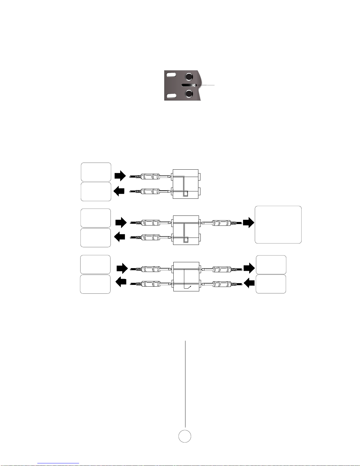
Hosa Technology PHB-265 User manual

©1999 Hosa Technology, Inc.
Photos, drawings and/or text may not be reproduced photographically, electronically, mechani-
cally or by any other means without the express, written consent of Hosa Technology, Inc.
OWNER'S MANUAL
®
MODEL PHB-265
PATCH BAY

Patch Bay Instructions
®
Patch bays are intended for insertion into the
signal path between multi-track recorders and
audio mixing consoles in home and commer-
cial studios. Connecting the patchbay between the
tape deck and mixer allows very convenient and
flexible signal-routing and re-patching, without
crawling behind the equipment every time a change
becomes necessary.
The inputs and outputs of outboard signal
processors like reverbs, delays and compressors are
also routed through the patch bay, making it simple to
add such effects into the signal path by employing
short, patch-bay cables to connect one device's
output to another device's input at the front of the bay
(much the way old-time telephone operators con-
PHB-265
nected telephone calls). Often, multiple patch bays
are used so that every sound source, every signal
processor, and every sound destination can be within
fingertip reach.
Certain conventions and terminology have
developed over the years, regarding the manner in
which studio gear is connected to the patch bay, and
regarding the type of patch bays used. This manual
follows and explains those conventions and attempts
to de-mystify the terminology used to describe the
various types of patch bays.
Each channel
of your
new Hosa model PHB-265 can be easily config-
ured via front-panel switches to any of the three
main types of bays.
Patch-bay connections can seem confusing at first until you've grasped
the concepts. As you read this manual, it will help if you maintain a
vivid mental picture of the
direction of signal flow
, as though your audio
signal was water flowing through pipes, and your cables were hoses.
And when looking at a vacant jack in the bay, learn to think of it as a
source or a load, meaning that it's either offering signal
to
you or
accepting it
from
you, but never both!
Tip!
Patch-BayTypes
Patch Bays can be divided into three main categories, based upon the way signal may be routed. These
types are often referred to by the terms "Open" (De-Normalled), "Full-Normalled", and "Half-Normalled".
Fig. 1. Arrows indicate direction of signal-flow when
using the commonly accepted practice of employing
top-rear jacks to accept incoming signals, and
bottom-rear jacks to pass outgoing signals.
Rear Front
What Does "Normalled" Mean?
In a
general sense
, "Normalled" means "usually
(normally) connected", and it refers to the vertically-
oriented jack pairs at the rear of the bay. (See Fig.
1., this page.) For example, most recording studios
have the mixer's OUTPUTS "usually connected" with
the recorder's INPUTS as we have done in Fig.1.
For recording purposes, it is very convenient to have
signal "loop" through the bay in this manner (with the
permanent connections made at the rear) because
we can now intercept, divert or make substitutions for
the signal easily at the front of the bay in a number of
ways, depending upon the patch bay's configuration.
From
Mixer's Ch.
1 OUTPUT
To
Recorder's
Ch. 1 INPUT
Three Different Patch Bays in One.
Switchable Patch Bay
End View:
Source
Load
2

PHB-265
"Half-Normalled"
For "Half-Normalled" operation, switch to the
right, using a ball-point pen or other pointed
object. Switches are recessed to prevent
accidental changes.
3
Patch-BayTypes (Continued)
A "Half-normalled" bay is one which allows you to break the connection between the
rear
top and bottom
jacks simply by plugging a cable into the
bottom-front
jack. This is a very versatile configuration, allowing a
number of different signal-flow scenarios. Let's continue to build upon our original example.
REAR FRONT
Figure 2 (a., b., c.) Arrows indicate direction of signal flow. Notice that until a cable is inserted into the bottom-front jack,
signal is passed from top rear to bottom rear without interruption (a), and may also be accessed at the top front jack (b).
But when a cable is inserted into the bottom-front jack, signal flow from top jacks to bottom jacks is interrupted (c).
REAR FRONT
REAR FRONT
a.
b.
c.
Figure 2a. (above) shows a detail of the switching
jack (bottom-front position). With nothing connected
to the switching jack, signal passes directly from top
rear to bottom rear, or from mixer OUT to recorder IN
in our example, and the same mixer OUT signal is
also available at the top-front position. (Figure 2b.
above.) In other words, the top-front jack is now a
SOURCE; an extension of the mixer OUT.
Notice however that when a cable is plugged into the
bottom-front jack, (Figure 2c.) the connection is
broken between top and bottom jacks at the rear of
the bay. To examine why that's a good thing, let's
From
Mixer's Ch.
1 OUTPUT
To
Recorder's
Ch. 1 INPUT
say we wanted to run our Mixer's Channel 1 OUT-
PUT into a compressor before we send the signal on
to the recorder. All we have to do is connect the
compressor's IN and OUT to the corresponding front
jacks on the bay (Figure 2c.) and signal now flows
from the mixer's OUT to the compressor's IN and
from the compressor's OUT to the recorder's IN. And
this is all accomplished without crawling around on
your hands and knees behind your equipment.
In addition to inserting devices into the signal path,
the half-normalled bay configuration also allows you
to substitute a different signal altogether. In our
From
Compressor's
OUTPUT
To
Compressor's
INPUT
From
Mixer's Ch.
1 OUTPUT
To
Recorder's
Ch. 1 INPUT
From
Mixer's Ch.
1 OUTPUT
To
Recorder's
Ch. 1 INPUT
Top-front Jack is an
additional SOURCE
of signal from Mixer
Ch 1, AND signal
continues to rear-
bottom jack as well.
2 a., b., c.

4
example, let's say we needed to send a signal other
than the mixer's output signal to the recorder's
Channel 1 input. (A keyboard, for example.) All you
would have to do is plug that keyboard's cable into
the corresponding
bottom-front
jack of the bay. The
signal from the mixer's Channel 1 Output would be
interrupted, and the keyboard's signal would be
substituted. (Fig 2 d., below.)
Figure 2 d. Arrows indicate direction of signal flow. Here,
we have interrupted the "usually-connected" mixer-to-
recorder signal path just by connecting a keyboard's signal
to the bottom-front jack (which breaks the connection
between top and bottom in the back).
From
Mixer's Ch.
1 OUTPUT
To
Recorder's
Ch. 1 INPUT
From
Keyboard's
OUTPUT
Mixer's Channel 1
Output now exists
only as a potential
"source" at the top
front jack. It does not
continue to the
recorder because the
Keyboard's signal has
been substituted.
2 d.
PHB-265
"Full-Normalled"
(Switch to Left Position)
A "Full-normalled" bay is one which allows you to
break the connection between the
rear
top and
bottom jacks by plugging a cable into either the
bottom-front jack
or
the
top-front jack
.
This configuration is the most versatile of the various
types of bays because you can either "steal" source
signals or substitute different load signals simply by
plugging into either the top or bottom jacks.
Notice, however that the scenario in Figure 2b. on
Page 2 is not possible with a full-normalled bay
configuration. With a full-normalled bay, a signal
could never be sent to top front
and
bottom rear at
the same time as it can in a half-normalled bay.
Rear Front
With nothing
plugged into the
front jacks, signal
continues
uninterrupted from
top to bottom in
the rear.
Fig. 3. Full-Normalled
a.
b.
c.
d.
When a cable is
plugged into the
top-front jack, the
signal between top
and bottom in the
rear is interrupted.
When a cable is
plugged into the
bottom-front jack,
the signal between
top and bottom in
the rear is
interrupted.
Figure 3 (a., b., c., d.) Arrows indicate direction of signal
flow. The full-normalled bay acts just like a half-normalled
bay except for scenario "b." above. When a plug is
inserted into the top-front position of a full-normalled bay,
signal between top and bottom in the back is interrupted.
(Compare with half-normalled bay, Fig. 2b., Page 2.)
With cables plugged into
both top and bottom jacks
in the front, the signal
between top and bottom
in the rear is interrupted.
Source
Load
Source
Load
Source

Open or "De-Normalled"
Rear Front
PHB-265
(Switch to Middle Position)
In the Open or "De-Normalled" bay, signal applied to
the top-rear jacks is available at the top-front jacks,
and signal applied to the bottom-front jacks is
available at the bottom-rear jacks. Top-rear and
bottom-rear jacks are never connected to each other.
One use for the Open configuration is to connect
outboard reverbs or compressors or other signal-
processing gear. With the module set to "De-
Normalled", you can avoid unwanted signal loops
such as the one that would happen if you were to
connect a reverb's outputs directly to its own inputs.
Figure 4 a. shows how this works.
Another use for the Open configuration is to connect
pieces of equipment that have no inputs of their own.
For example, the Left and Right outputs of a CD
player could be connected to separate modules of
the bay, but since there are no corresponding "loads"
for those two channels (
i.e.,
You can't send any
signal TO the CD player, because it has no inputs),
there would be nothing to plug into the top-front
jacks. Therefore for the CD player and other "play-
only" gear, it makes sense to save space by dou-
bling-up and plugging the Left and Right CD Outputs
one above the other into the Top-Front and Bottom-
Front positions of a single bay module. (See Figure
4 b.)
Notice that Figure 4 b. is the only diagram showing
signal flowing from front to back in both top and
bottom positions. This is one instance where it is
helpful to break the "top-rear IN; bottom-rear OUT"
convention adhered to in every other diagram. Make
sure you label any such dual inputs clearly to avoid
confusion!
Rear Front
From
REVERB's
OUTPUT
To
REVERB's
INPUT
From CD
LEFT
Output
From CD
RIGHT
Output
To Mixer's
CD LEFT
INPUT
To Mixer's
CD RIGHT
INPUT
Top-Front Jack
is now a
REVERB
SOURCE
Bottom-Front
Jack is now a
REVERB
LOAD (input)
Figure 4a. Arrows indicate direction of signal flow. The
rear top & bottom jacks of Open ("De-Normalled") bays are
never connected to each other, even when no cables are
connected to the corresponding front jacks.
Figure 4b. Arrows indicate direction of signal flow. Open
or "De-Normalled" bays modules are often used to input
signal from devices that have no inputs of their own. This is
one instance that defies the convention of top-rear-IN,
bottom-rear-OUT. It's a great way to save space in the bay.
4 b.
4 a.
Using theWhole Bay
5
Take a moment o look at Fig.2c. again (Page 2). It
shows how a mixer's signals could be routed out to a
compressor and then back through the bay to the
recorder. What it
doesn't
show, is how the cables
were run to and from the compressor's input and
output. One way, of course would be to string cables
directly to and from the compressor's input and
output, but if the compressor isn't near the patch bay,
the long cable runs to the front of the bay would be in
the way. Abetter way to accomplish this would be to
connect the compressor's ins and outs to the rear
panel of the patch bay, too. (
See Fig. 5, Page 5
)
Then, all we need are short patch cables from the
corresponding front-panel jacks that represent the
compressor's in and out to the front-panel jacks that
represent the mixer (source) and the recorder (load)
at patchbay Channel One.
In this manner, each signal source and each destina

COMP OUT
MIX 1 OUT
TAPE 1 IN
Figure 5. Arrows indicate direction of signal flow. After plugging the compressor's input and output into the
rear
jacks of
patch-bay Channel 9, we have created a Compressor "source" at the top-
front
jack of Channel 9, and a Compressor
"load" (input) at the bottom-
front
jack of Channel 9. Therefore, using short patch cables as shown above, we have
created the following signal path: Mixer's Output to Compressor's Input, and Compressor's Output to Recorder's Input. So
the signal from Channel One at the Mixer will now be compressed before recording.
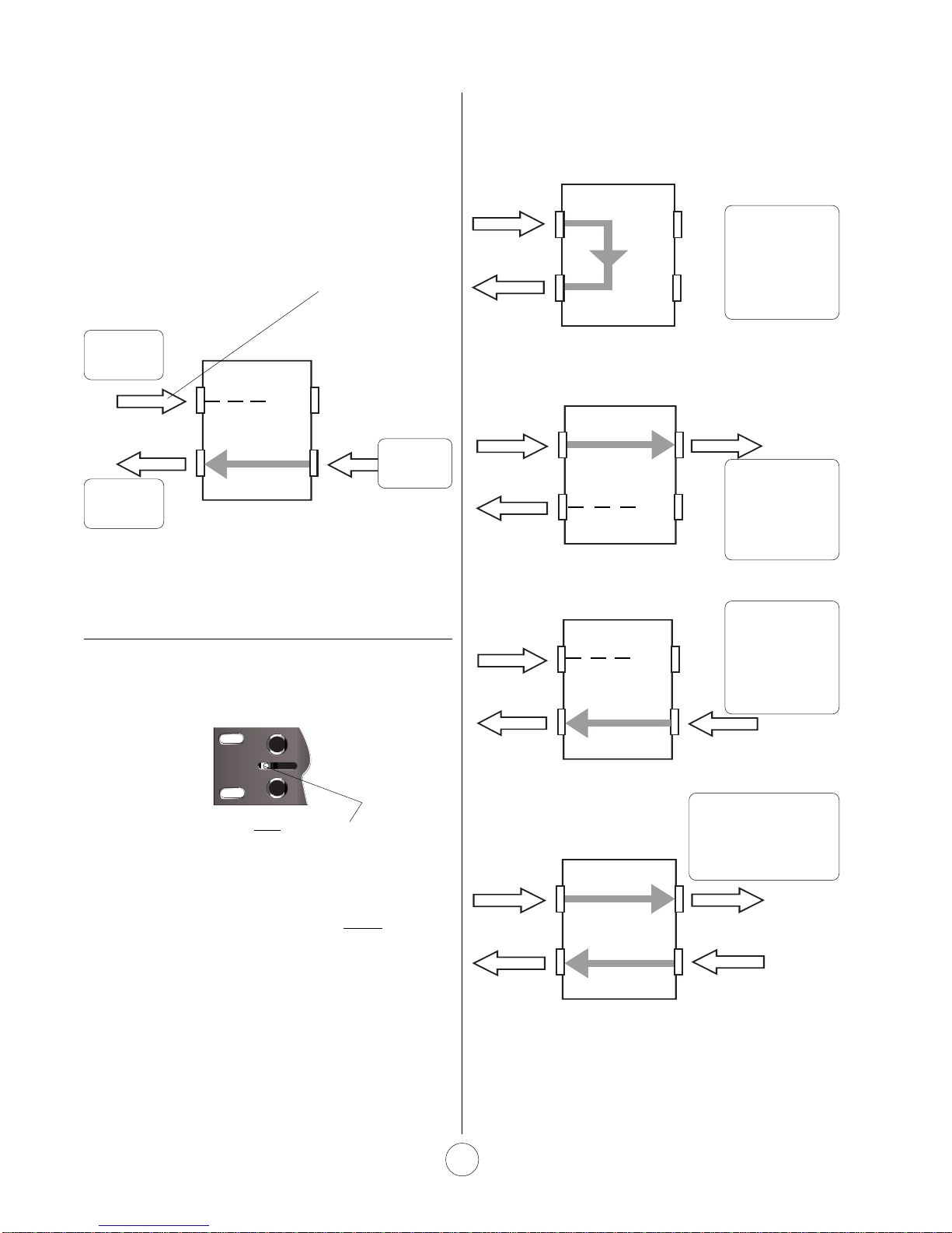
Note also, that Patch-bay Channel One is set for HALF-NORMALLED, meaning that with nothing plugged into the bottom-
front jack for that channel, signal will continue from the mixer to the recorder. But when we plug in the patch cables as
above, signal is diverted first to the Compressor and then back to the Recorder. The Compressor's patch-bay channel
however, is set for DE-NORMALLED, so that we won't create an unwanted loop from the Compressor's outputs to its own
inputs when cables are removed from the patch bay's front panel.
Set for Half-Normalled Set for De-Normalled
Figure 5
6
MIX 2 OUT MIX 3 OUT MIX 4 OUT MIX 5 OUT MIX 6 OUT MIX 7 OUT MIX 8 OUT
TAPE 1 IN TAPE 3 IN TAPE 4 IN TAPE 5 IN TAPE 6 IN TAPE 7 IN TAPE 8 IN
tion, including all outboard reverbs, delays, compres-
sors and other signal processors, can have its own
patch-bay channel, allowing easy connections to any
other piece of gear. Studios with large mixing
consoles, multiple reocrders and dozens of pieces of
outboard equipment require more than one patch bay
to meet their needs. Multiple bays are usually racked
one-above-the-other in a single rack so that short
patch cables can reach all front-panel ins and outs.
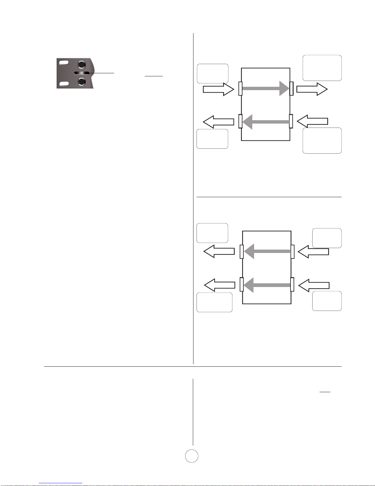
Balanced/Unbalanced
The PHB-265 is an UNBALANCED patch bay when
used in the Half-Normalled or Full-Normalled configu-
rations. But it can be used as a BALANCED bay in
the Open or De-Normalled configuration only (with
the switch in the center position).
"Balanced" audio connections have three conductors
representing positive, negative and ground. Audio
signal is kept separate from the ground conductor in
such connections. "Unbalanced" audio connections
allow the ground to "share" the negative conductor
and are transmitted through cables and jacks having
only two conductors.
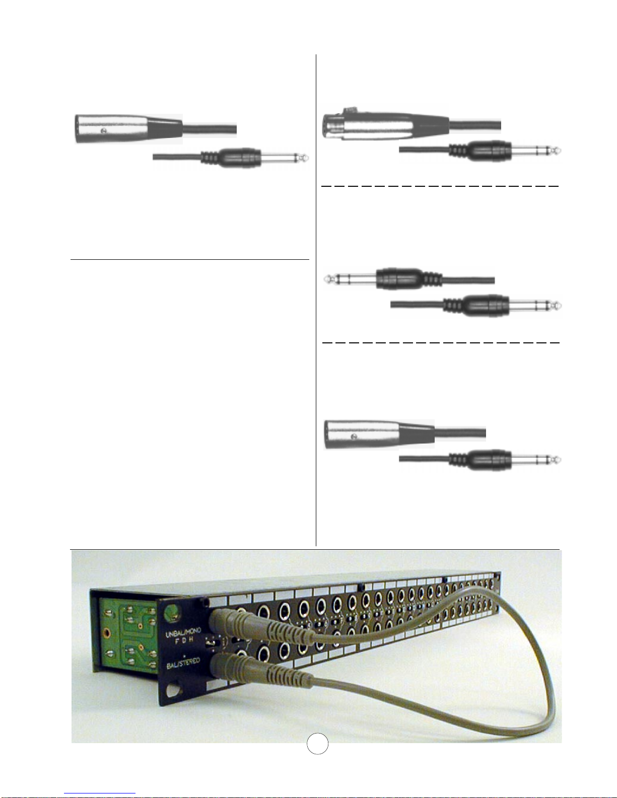
If you intend to use the PHB-265's full-normalled or
half-normalled configurations with balanced audio
gear, you should use a cable that "unbalances" the
signal before it gets to the bay:
Figure 6
a. Incoming signal
b. Incoming/Outgoing signal
Figure 6a. For signals coming into the bay from balanced
equipment that features XLR outputs, use a cable like
Hosa's PXF-100 series, which "unbalances" the signal
(ground "shares" the negative conductor) for use with the
PHB-265 when using the half-normalled or full-normalled
configurations.
Connections
Hosa PXF-100 Series Cables
Hosa CPP-100 SERIES
Figure 6b. For signals entering or leaving the bay and
connecting to balanced equipment that features balanced
1/4" (Tip, Ring, Sleeve) jacks, use a cable like Hosa's
PXM-100 series which "unbalances" the signal, allowing
ground to "share" the negative conductor.
COMP IN

Figure 6c. For signals leaving the bay and connecting to
balanced equipment that features balanced XLR inputs,
use a cable like Hosa's PXM-100 series which "unbal-
ances" the signal for use with the PHB-265 bay when using
the either half-normalled or full-normalled configurations.
Figure 6 c.
Outgoing signal
Hosa PXM-100 SERIES
Balanced signal connections are less prone to
interference than unbalanced, especially in long
cable runs. But in most cases, unbalancing runs of
10-15 feet to outboard gear in the manner detailed
above will make no audible difference in the audio. If
your studio is in an electronically "noisy" location, and
you experience increased noise in the audio signal
when unbalancing the signal runs to otherwise
balanced equipment as outlined above, then switch
the patchbay channels that are affected to the de-
normalled (middle) switch position, and use balanced
cables as in Fig. 7.
Although neither full nor half-normalling is possible in
the de-normalled (middle) switch position, it is still
possible to patch signals from top-rear to bottom-rear
jack positions by using a short patch cable between
top and bottom in the front as shown in the photo
below. (For balanced gear, use a balanced cable like
the the one shown in Fig. 7b.)
Figure 7. BALANCED CABLES
a. Incoming signal
b. Incoming/Outgoing signal
Figure 7 a, b, c. For patchbay modules set to the de-
normalled position (middle switch position), balanced
connections can be maintained to balanced gear by using
the appropriate balanced cable such as these (above)
offered by Hosa.
Hosa CSS-100 Series Cables
c. Outgoing signal
Hosa STX-100M Series Cables
Hosa STX-100F Series Cables
7
When using the center (de-normalled) switch position, it is still
possible to send signals from top-rear to bottom rear by connecting
a short patch cable to the front jacks as shown.

For connections at the front of the bay, you'll need
multiple, short patch cables in either balanced 1/4"
phone or unbalanced 1/4" phone. Hosa offers color-
coded patch-bay cable sets of eight shielded cables
each. They are available terminated in unbalanced
1/4" phone (CPP-830, CPP-845, CPP-890) and
balanced 1/4" phone (CSS-845 and CSS-890), in a
variety of convenient lengths specifically for use with
professional patch bays. The dealer from whom you
purchased your PHB-265 can help you find an
appropriate set of patch-bay cables.
Patch-Bay Cable Sets
Hosa
CSS-845
BALANCED
PATCH CABLE SET
YOUR TALENT. OUR CONNECTIONS.
Hosa Technology, Inc. 6920 Hermosa Circle,
Buena Park CA 90620-1151 (714) 736-9270
®
Labelling
By now, you're probably aware of the importance of
labelling all of your patch-bay connections. With so
may dozens of patch points (especially when more
than one patch bay is employed), you'll never keep
track of them all without labelling. The white areas
above and below the front-panel jacks are available
for labelling each jack. Make sure to use a "wipe-off"
marker, like the ones used on white presentations
boards, or get a "grease" pencil from an art supply
store. DON'T use permanent markers. If you do,
and then decide later to reconfigure the bay, you'll be
stuck with your old labels! ❑
Table of contents
Popular Cables And Connectors manuals by other brands

Keysight Technologies
Keysight Technologies 11667B Operating and service manual

XPOtool
XPOtool 62690 Operation manual

Heitronic
Heitronic 21041 Installation and operating instructions

Signat
Signat Porsche S30.7230-230 brochure

Foxun
Foxun SP148-HD4K2K operating instructions

Gefen
Gefen EXT-HDMI1.3-142 user manual

Kramer
Kramer RTBUS-28XL quick start guide

Philips
Philips SDW5060O Specifications

ADC
ADC Transport System Cable DS1C Specification sheet

Kramer
Kramer CLS-AOCH/60 Series installation instructions

National Instruments
National Instruments NI 9924 USER GUIDE AND SPECIFICATIONS

Madison Electric Products
Madison Electric Products WireSmart MH8010 instruction manual