Hosen MINI WASH MOVING HEAD User manual

1
MINI WASH MOVING HEAD
USER MANUAL
(Suitable for 1w or 3w* mode)

2
1. BEFORE YOU BEGIN
What is included
1w or 3w x18 pcs Min wash
User Manual
Unpacking Instructi ns
I ediately upon receiving a fixture, carefully
unpack the carton, check the contents to ensure
that all parts are present, and have been received
in good condition. Notify the shipper
i ediately and retain packing aterial for
inspection if any parts appear da aged fro
shipping or the carton itself shows signs of
ishandling. Save the carton and all packing
aterials. In the event that a fixture ust be
returned to the factory, it is i portant that the
fixture be returned in the original factory box
and packing.
AC P wer
To deter ine the power require ents for a
particular fixture, see the label affixed to the back
19
THERMAL
Maxi u a bient
te perature.......................................................... .....104°F(40°C)
CONTROL & PROGRAMMING
Data input .................................................................. locking 3-pin
XLR ale socket
Data output .............................................................. locking 3-pin
XLR fe ale socket
Data pin configuration ...................................................pin 1 shield,
pin 2 (-), pin 3 (+)
Protocols...................................................................DMX-512USITT
DMX
Channels ....................................................................................12
WARRANTY INFORMATION
Warranty ..................................................................
1-year limited warranty
Remark: LED bead no in luding.

18
DMX M de
This ode allows the unit to be controlled by any
universal DMX controller. If you are unfa iliar with
DMX, please read the DMX Pri er on page #19.
1)
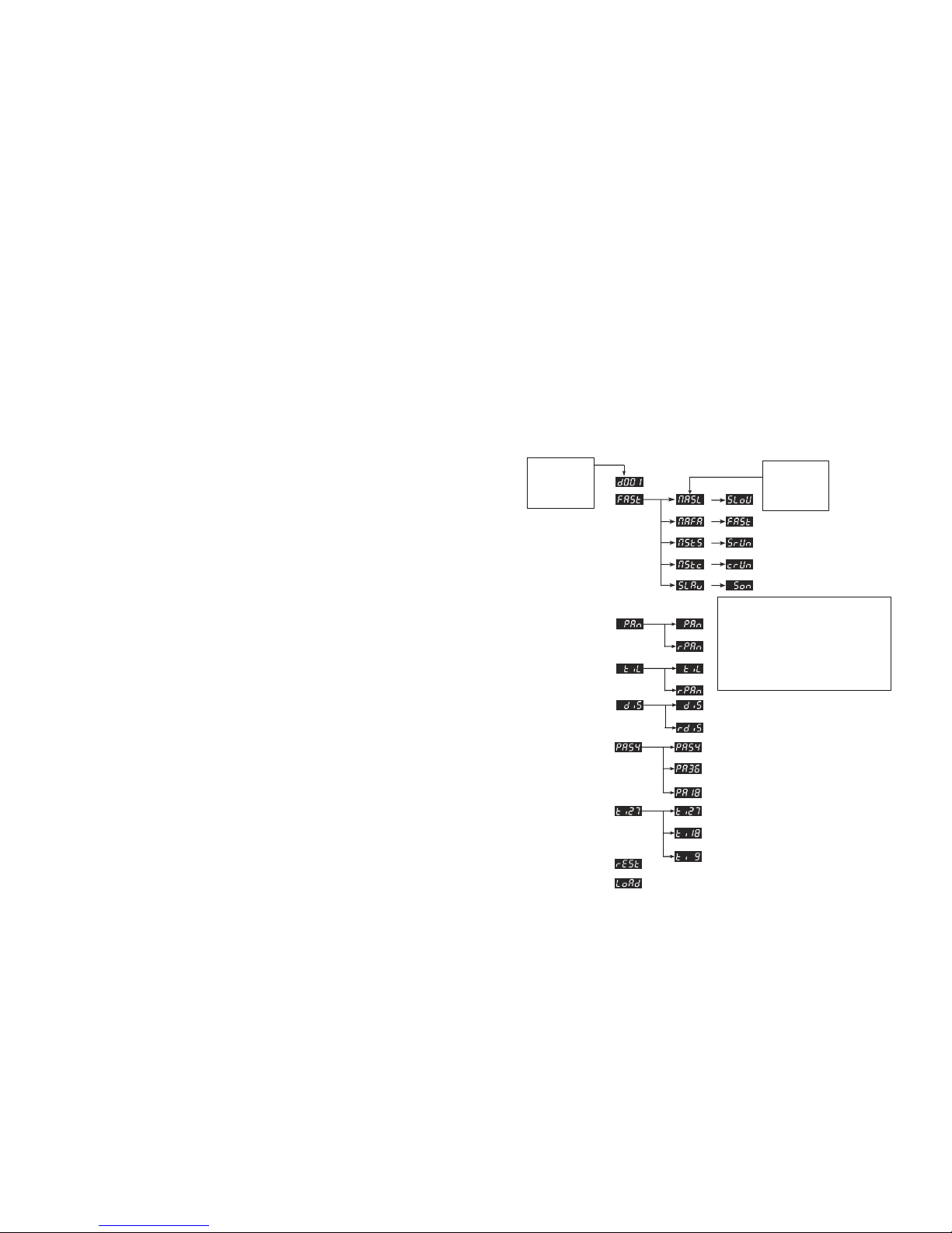
The default ode for the fixture is DMX,
which appears as on the LED
Readout.
4
5. APPENDIX
Technical Specificati ns
POWER
Switch-selectable power settings ................................120V
60Hz AC or 230V 50Hz
Fuse............................................................................... 2A 250V
LIGHT SOURCE
LED..............................................................
1/3w*18pcs (RGB, Edison Brand)
RANGE
Pan ...................................................................................... 540
Tilt........................................................................................180
3
plate of the fixture or refer to the fixture s
specifications chart. A fixture s listed current
rating is its average current draw under nor al
conditions. All fixtures ust be powered directly
off a switched circuit and cannot be run off a
rheostat (variable resistor) or di er circuit, even
if the rheostat or di er channel is used solely
for a 0% to 100% switch. Before applying power
to a fixture, check that the source voltage atches
the fixture s require ent. Check the fixture or
device carefully to ake sure that if a voltage
selection switch exists that it is set
to the correct line voltage you will use.
Warning!
Verify that the voltage select
switch on your unit atches the
line voltage applied. Da age to
your fixture ay result if the line
voltage applied does not atch
the voltage indicated on the
voltage selector switch. All
fixtures ust be connected to
circuits with a suitable Earth
Ground.
Figure 1 - AC Voltage Switches

4
Not all fixtures have a voltage switch,
please be sure to connect to the proper voltage
2. Intr ducti n
Features
CONTROL FEATURES
4/12- hannel DMX-512 LED moving yoke
Pan: 540° / tilt: 180°
RGB olor mixing
Variable electronic strobe
Variable electronic di er (0 -100%)
Vector speed channel for pan/tilt, RGB color ixing and color
acros
Built-in ove ent acros via aster/slave or DMX
ADDITIONAL FEATURES
User-selectable basic or advanced operating odes
User-electable pan/tilt ranges
Pan:540°,360°,180°
Tilt:180°,90°
17
1) Use standard DMX cables to daisy chain your
units together via the DMX connector on the rear
of the units. Proper perfor ance it ay be
necessary to use a ter inator at the last fixture. For
ore infor ation about ter inators, see page 8.
2) Choose a unit to function as the Master. Select
NAFA/NASL or NStS (see below for readout)
depending upon which aster ode you require.
The aster unit ust be the first unit in line.
Finally, chain the units together using DMX
cable.
Master Auto or nASL
Master Sound n5t5 beco es
when confir ed
3) Select slave function by using the Up/Down
keys to reach SLAv in the Master/Auto enu on
the slave units, and they will react in the sa e as
the Master.
Slave beco es
when confir ed

16
2) Press enter to confir your selection.
Operati n
Stand-Al ne M de (Aut M de):
This ode allows a single unit to run to a factory
installed progra in one of two speeds.
1) . To set the fixture in auto ode fast,select
nAFA
Once confir ed the display
reads
FAST
2) To set the fixture in auto ode Slow, select
nASL Once confir ed the display
reads sl w
Master/Slave M de (Master S und):
This ode will allow you to link up to 32 units
together without a controller.
5
Co pact and lightweight
LED display enu with invert
Reset to factory setting option
Display auto on/of
Pan/tilt invert option
Pan cooled
Opti nal C ntr llers
Easy controller(CA-9)
DMX Channel Summary -152Channel M de f r Wash
CHANNEL FUNCTION
1 Pan
2 Pan Fine
3 Tilt
4 Tilt Fine
5 Vector Speed(Pan/Tilt)
6 Di er /Strobe
7 Red
8 Green
9 Blue
10 Color acros
11 Vector Speed(Color)
12 Move ent Macros

6
Fuse Replacement
With a flat head screwdriver wedge the fuse holder out of its housing.
Re ove the da aged fuse fro its holder and replace with exact
sa e type fuse. Insert the fuse holder back in
its place and reconnect power.
Le ns
Proje tor He ad
LED Display
Control
panel
DMX Ou t
DMX In
Fuse
ICE Power
15
TO SET THE MAX I MUM PAN ANGLE:
1) Press the Mode button until it shows
or or
2) Use the Up/Down buttons to set to the
desired inversion, press enter to confir .
TO SET THE MA X I MUM TILT ANGLE:
1) Press the Mode button until it shows or
or
2) Use the Up/Down buttons to set to the desired
inversion, press enter to confir .
Service Functi ns
TO RESET THE FIXTURE:
1) Press the Mode button until the display
shows
2) Press enter to confir your selection.
TO RESTORE ALL SETTINGS TO THEIR
FACTORY DEFAULTS:
1) Press the ode button until the display
reads

14
User C nfigurati ns
TO SET THE PAN TO INVERTING OR NON- INVERTING:
1) Press the Mode button until it shows or
2) Use the Up/Down buttons to set to the desired
inversion, press enter to confir .
TO SET THE TILT TO INVERTING OR NON- INVERTING:
1) Press the Mode button until it shows or
2) Use the Up/Down buttons to set to the desired
inversion, press enter to confir .
TO SET THE LED READOUT TO INVERTING OR NON-
INVERTING:
1) Press the Mode button until it shows or
2) Use the Up/Down buttons to set to the
desired inversion, press enter to confir .
TO SET THE DMX CHANNEL CONFIGURATION:
1) Press the Mode button until it shows
12CH
2) Use the Up/Down buttons to set to the desired
inversion, press enter to confir .
7
Fixture Linking
You will need a serial data link to run light shows of one or ore
fixtures using a DMX-512 controller or to run synchronized shows
on two or ore fixtures set to a aster/slave operating ode. The
co bined nu ber of channels required by all the fixtures on a serial
data link deter ines the nu ber of fixtures the data link can support.
Important: Fixtures on a serial data link must be
daisy chained in one single line. To
comply with the EIA-
4 5
standard no more than 32 devices should
be connected on one data link.
Connecting more than 32
fixtures on one serial data link without
the use of a DMX optically-isolated
splitter may result in
deterioration of the digital DMX signal.
Maxi u reco ended serial
data link distance: 500 eters
(1640 ft.) Maxi u
reco ended nu ber of fixtures
on a serial data link: 32 fixtures

8
Data Cabling
To link fixtures together you ust obtain data cables.
You can purchase CHAUVET-certified DMX cables
directly fro a dealer/distributor or construct your own
cable. If you choose to create your own
cable please use data-grade cables that can carry a high
quality signal and are less prone to electro agnetic
interference.
DMX DATA CABLE
Use a Belden? 9841 or equivalent cable which eets
the specifications for EIA RS-485 applications.
Standard icrophone cables cannot trans it DMX
data reliably over long distances. The cable will have
the following characteristics:
2-conductor twisted pair plus a shield
Maximum capacitance between
conductors 30 pF/ft.
Maximum capacitance between
conductor and shield 55 pF/ft.
Maximum resistance of 20 ohms / 1000 ft.
Nominal impedance 100 140 ohms
CAB LE C ONN ECTORS
Cabling ust have a ale XLR connector on one end and a fe ale
XLR connector on the other end.
13
Menu Map
Use the <UP>,<DOWN >,
and <ENTER> buttons to
s roll through these menu
item s
When navigating the menu :
Use the UP button to move up .
Use the DOWN button to move down
.
Use the ENTER button to move right
.
Use the MODE buton to move left or ,
-to scroll through the left most
.items in the menu map
Use the <MODE/ESC>
button to scroll through
these menu items

12
Master/Slave Fixture Linking
1.Connect the ( ale) 3 pin connector side of the DMX cable to the
output (fe ale) 3 pin connector of the first fixture.
2.Connect the end of the cable co ing fro the first fixture which
will have a (fe ale) 3 pin connector to the input connector of the
next fixture consisting of a ( ale) 3 pin connector. Then, proceed
to connect fro the output as stated above to the input of the
following fixture and so on
Often, the setup for Master-Slave and Standalone operation requires that the first
fixture in the hain be initialized for this purpose via eithe settings in the ontrol panel
or DIP-r swit hes. Se ondarily, the fixtures that follow may also require a slave
setting. Please onsult the
Operating Instru tions
se tion in this manual for omplete
instru tions
for this type of setup and onfiguration.
9
DMX c nnect r c nfigurati n
INPUT
CAUTION :Do not allow contact between the co on and the
fixture ‘s chassis ground. Grounding the co on can cause a
ground loop, and your fixture ay perfor erratically. Test cables
with an oh eter to verify correct
polarity and to ake sure the pins are not grounded or shorted to the
shield or each other.
3-PIN TO 5- PIN CON VE R SION CHAR T
Note! If you use a controller with a 5 pin DMX output connector, you
will need to use a 5 pin to 3 pin adapter. CHAUVET Model No:
DMX5M, or DMX5F. The
chart below details a proper cable conversion:
3 PIN TO 5 PIN CONVERSION CHART
C nduct r 3 Pin Fe ale (output)
5 Pin Male (Input)
Gr und/Shield
Pin 1
Pin 1

10
Data ( - ) signal Pin 2
Pin 2
Data ( + ) signal Pin 3
Pin 3
Do not use Do not use
Setting up a DMX Serial Data Link
1. Connect the ( ale) 3 pin connector side of
the DMX cable to the output (fe ale) 3 pin
connector of the controller.
2. Connect the end of the cable co ing fro
the controller which will have a (fe ale) 3
pin connector to the input connector of the
next fixture consisting of a ( ale) 3 pin connector.
3. Then, proceed to connect fro the output
as stated above to the input of the following
fixture and so on.
DMX Data Cables
11
Order Code Description
DMX1.5 DMX Cable 1.5 /4.9ft
DMX4.5 DMX Cable 4.5 /14.8ft
DMX10 DMX Cable 10 /32.8ft
Universal DMX C ntr ller
Table of contents
Other Hosen Dj Equipment manuals
Popular Dj Equipment manuals by other brands

thomann
thomann Stairville Crown FX PAR 77 user manual

Chauvet DJ
Chauvet DJ Beamer 8 Quick reference guide

Blizzard Lighting
Blizzard Lighting OBERON PROFILE NZ user manual

Vestax
Vestax FDG-1 owner's manual

Coemar
Coemar Softlite LED RGBW instruction manual

Martin
Martin THRILL Compact PAR 64 LED Safety and installation guide