Hoshizaki RNC-120A-LA User manual

NO. 74MA-527
ISSUED: FEB. 29, 2000
REVISED:
HOSHIZAKI
COUNTER SHOWCASE
MODEL RNC-A SERIES
(HA)
SERVICE MANUAL

74MA5270002
CONTENTS PAGE
1. FOR SAFETY AND BEST OPERATING RESULTS----------------------------------------- 1
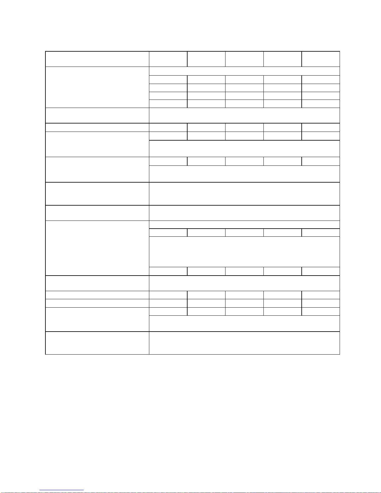
2. SPECIFICATIONS ---------------------------------------------------------------------------------- 2
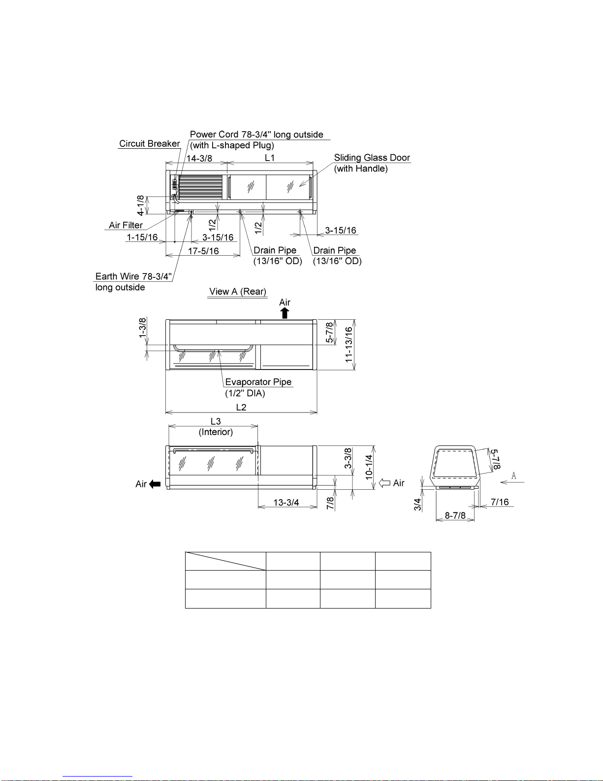
3.DIMENSIONS ---------------------------------------------------------------------------------------- 3
[a] RNC-90A-RA, RNC-120A-RA---------------------------------------------------------------- 3
[b] RNC-150A-RA, RNC-180A-RA, RNC-210A-RA----------------------------------------- 4
[c] RNC-90A-LA, RNC-120A-LA ---------------------------------------------------------------- 5
[d] RNC-150A-LA, RNC-180A-LA, RNC-210A-LA ------------------------------------------ 6
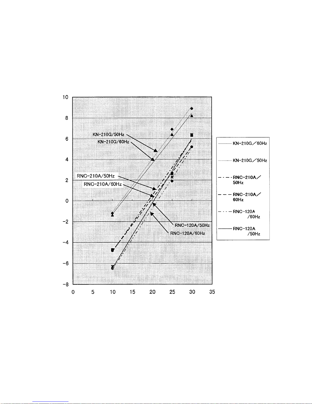
4. PERFORMANCE DATA --------------------------------------------------------------------------- 7
5.REFRIGERATIONCIRCUIT ----------------------------------------------------------------------- 8
6.WIRINGDIAGRAM ---------------------------------------------------------------------------------- 9
7.CONSTRUCTION ----------------------------------------------------------------------------------10
8. REMOVAL AND REPLACEMENT------------------------------------------------------------- 11
[a] FRONT GLASS AND TOP COVER -------------------------------------------------------11
[b] TOP FRAME ------------------------------------------------------------------------------------12
[c] SEPARATOR AND SIDE FRAME ---------------------------------------------------------12
[d] BREAKER COVER AND LOUVER -------------------------------------------------------12
[e] PIPE HOLDER ---------------------------------------------------------------------------------13
[f] WATERPROOF COVER ---------------------------------------------------------------------13
9.REFRIGERANTSERVICEINFORMATION---------------------------------------------------15
10. CONSTANT PRESSURE EXPANSION VALVE AND REFRIGERANT CHARGE --17
[a]SPECIFICATIONS -----------------------------------------------------------------------------17
[b]FUNCTION---------------------------------------------------------------------------------------17
[c]CONSTRUCTION ------------------------------------------------------------------------------17
[d] REPLACEMENT-------------------------------------------------------------------------------18
11. SERVICE DIAGNOSIS----------------------------------------------------------------------------19

74MA5270002 1
1. FOR SAFETY AND BEST OPERATING RESULTS
IMPORTANT
Hoshizaki Counter Showcase is intended for temporary food display.
Constructed with much glass, this showcase gives relatively insufficient heat
insulationandpoor cooling performancecomparedwith refrigerators ingeneral.
For safe and efficient operation, be sure to follow the instructions below.
1) Do not leave foods in the showcase after service hours, or they may dry or spoil.
2) Foods that should not dry must be covered or wrapped up in a plastic film.
3) Precool foods in a refrigerator before storing them in the showcase.
4) Do not leave the Doors open or open them too frequently.
5) Do not pack the showcase with foods.
6) The showcase should not be exposed to direct sunlight or located next to ovens, grills or
other high heat producing equipment.
7) The ambient temperature should not exceed 86°F.

2. SPECIFICATIONS
MODEL RNC-90A-RA
-LA RNC-120A-RA
-LA RNC-150A-RA
-LA RNC-180A-RA
-LA RNC-210A-RA
-LA
1 Phase 115-120V 60Hz
2.5A 2.4A 3.1A 3.1A 3.1A
11A 11A 15A 15A 15A
145W 146W 195W 195W 195W
AC SUPPLY VOLTAGE
AMPERAGE
STARTING AMPERAGE
ELECTRIC CONSUMPTION
POWER FACTOR 58% 61% 54% 54% 54%
PULL DOWN TIME (10°C)
SATURATION TEMPERATURE Less than 45 min. (Ambient Temp. 86°F, No Load)
44.6°F (Ambient Temp. 86°F, No Load)
NET CAPACITY 0.85 cu.ft. 1.3 cu.ft. 1.8 cu.ft. 2.3 cu.ft. 2.8 cu.ft.
35-7/16” 47-1/4” 59-1/16” 70-7/8” 82-11/16”
EXTERIOR DIMENSIONS (W)
(D)
(H) 11-13/16”
10-1/4”
20-7/8” 32-11/16” 44-1/2” 56-5/16” 68-1/8”
INTERIOR DIMENSIONS (W)
(D)
(H) 10-1/4”
6-5/16”
EXTERIOR
INTERIOR
INSULATION
Glass, Rigid PVC, ABS Resin
Stainless Steel
Polyurethane Foam
REFRIGERATION SYSTEM
DEFROST SYSTEM Convection Cooling
None
Hermetic
75W 75W 130W 130W 130W
Fin and Tube type (Air-cooled), Fan Motor 2P
(UPPER) Bare Tube type, (LOWER) Pipe on Sheet type
Constant Pressure Expansion Valve
R134a
COMPRESSOR OUTPUT
CONDENSER
EVAPORATOR
REFRIGERANT CONTROL
REFRIGERANT
REFRIGERANT CHARGE 4.8 oz. 6.3 oz. 4.6 oz. 6.3 oz. 7.4 oz.
ELECTRIC CIRCUIT PROTECTION
COMPRESSOR PROTECTION Circuit Breaker, Grounding Wire
Auto-reset Protector - Compressor
SLIDING DOOR 2 pcs. 2 pcs. 4 pcs. 4 pcs. 4 pcs.
NET WEIGHT 46 lbs. 55 lbs. 66 lbs. 75 lbs. 84 lbs.
2 pcs. 3 pcs. 4 pcs. 5 pcs. 6 pcs.ACCESSORIES BOARD
CAP
VINYL HOSE 2 pcs.
1 pc. (19/32” DIA x 3/4”DIA x 59”)
AMBIENT TEMP.
RELATIVE HUMIDITY
VOLTAGE VARIATION
50 - 86°F
Max. 60%
Rated voltage ±10%
* Relative humidity exceeding 60% may cause condensation on the exterior.
* We reserve the right to make changes in specifications and design without prior notice.
274MA5270002

74MA5270002 3
3. DIMENSIONS
[a] RNC-90A-RA, RNC-120A-RA
L1 L2 L3
RNC-90A-RA 20-1/16” 35-7/16” 20-7/8”
RNC-120A-RA 31-7/8” 47-1/4” 32-11/16”
Width
Model
Unit:inch

74MA5270002
4
[b] RNC-150A-RA, RNC-180A-RA, RNC-210A-RA
L1 L2 L3
RNC-150A-RA 21-7/16” 59-1/16” 44-1/2”
RNC-180A-RA 27-3/8” 70-7/8” 56-5/16”
RNC-210A-RA 33-1/4” 82-11/16” 68-1/8”
Width
Model
Unit:inch

74MA5270002 5
[c] RNC-90A-LA, RNC-120A-LA
L1 L2 L3
RNC-90A-LA 20-1/16” 35-7/16” 20-7/8”
RNC-120A-LA 31-7/8” 47-1/4” 32-11/16”
Width
Model
Unit:inch

74MA5270002
6
[d] RNC-150A-LA, RNC-180A-LA, RNC-210A-LA
L1 L2 L3
RNC-150A-LA 21-7/16” 59-1/16” 44-1/2”
RNC-180A-LA 27-3/8” 70-7/8” 56-5/16”
RNC-210A-LA 33-1/4” 82-11/16” 68-1/8”
Width
Model
Unit:inch

74MA5270002 7
4. PERFORMANCE DATA
The following is a reference data showing the relationship between the ambient and interior
temperatures measured at the center of the interior, 60mm above the board.
Conditions: Ambient temperature 30°C (86°F), 50/60Hz, relative humidity 50%, AC100V
Testunits: RNC-210A and KN-210G domestic models (+ RNC-120A for reference)
Ambient Temperature [°C (°F)]
Interior Temperature [°C (°F)]
(32) (41) (50) (59) (68) (77) (86) (95)
(50)
(46.4)
(42.8)
(39.2)
(35.6)
(32)
(28.4)
(24.8)
(21.2)
(17.6)

74MA5270002
8
5. REFRIGERATION CIRCUIT
Refrigerant 134a
Compressor
Condenser
Drier Expansion
Valve
Evaporator
(Upper) Evaporator
(Lower)
* The Expansion Valve controls the refrigerant flow rate to stabilize the pressure at the
Evaporator inlet.

74MA5270002 9
6. WIRING DIAGRAM
CM Compressor
SC Start Capacitor
FM Fan Motor
ELB Circuit Breaker
PTC PTC Thermistor
OL Overload Relay

74MA5270002
10
7. CONSTRUCTION
Sliding Glass
Door
Board
Side Glass
Packing (Side)
SideCover
Side Frame
TopCover
FrontCover
Separator
EvaporatorPipe
Separator
Cover
Front Glass
Packing (Front)
CenterFrame
Louver
BreakerCover

74MA5270002 11
8. REMOVAL AND REPLACEMENT
CAUTION
1. Be sure to unplug the showcase before removing or replacing the parts.
2. Handle the glass parts with care.
[a] FRONT GLASS AND TOP COVER
CAUTION
In some cases, the Top Cover is tightly locked on the Top Frame and will not
come off easily. Remove it with care to avoid injury.
1) Remove the Side Cover and Separator Cover.
2) Hold the Front Glass from both inside and
outside, and push it outward.
3) Remove the Sliding Glass Doors and Side
Glass.
4) Put your hand in the channel of the Top Cover
where the Front Glass was placed, and lift off
the Top Cover. See Fig. 1.
Note: The Top Cover cannot be removed from
therear.
5) Refit the Front Glass and Top Cover at the same
time as shown in Fig. 2. Do not twist the Front
Packing.
Fig. 1
Fig. 2
TopCover
Top Frame
Good
No good
Front
Glass
Slider (plastic)

74MA5270002
12
[b] TOP FRAME
* The Top Frame (Aluminum) on the machine compartment can be removed by unfastening
two screws on the top and two screws on the side.
* The Top Frame on the refrigerated compartment
can be removed by unfastening four screws on
the top and two screws on the bottom (for the
Center Frame) and by removing the Evaporator
Pipes from the Pipe Holder. See Fig. 5.
* To assemble the Top Frame with the Separator
or Side Frame, push the Top Frame to the rear
end and secure it with the screws. Otherwise the
Top Cover cannot be mounted. See Fig. 3.
[c] SEPARATOR AND SIDE FRAME
*TheSeparator and SideFrameon the refrigeratedcompartmentare sealed withtransparent
silicone sealant where in contact with the Water Pan (Stainless Steel). Be sure to reseal
those parts when reassembling them.
* To shut out hot air from the machine compartment, seal the top of the Separator.
[d] BREAKER COVER AND LOUVER
1) Remove the Side Frame on the machine
compartment.
Note: Do not try to remove the Breaker Cover
byforcewithoutremovingtheSideFrame,
or the plastic Breaker Cover may break.
2) Make sure the showcase is unplugged, and
move the Circuit Breaker to the “ON” position.
3) Slide off the Breaker Cover.
Note: With the Circuit Breaker in the “OFF”
position, the Breaker Cover will hit the
switch and cannot slide.
4) Remove the Louver.
Note: To prevent the entrance of water, the Circuit Breaker is provided with a silicone
Waterproof Cover. Be careful not to damage it when attaching the Breaker Cover.
See “[f] WATERPROOF COVER”.
Fig. 3
Fig. 4
Separatoror
Side Frame
Space
Rear
Louver
BreakerCover
Side Frame Separator
Breaker
BreakerCover
Waterproof
Cover(silicone)

74MA5270002 13
[e] PIPE HOLDER
Note: The Evaporator Pipes are tightly snapped in
the Pipe Holder and should be removed and
refitted carefully one by one.
1) Remove the Evaporator Pipes from the Pipe
Holder.
2) Twist the Pipe Holder and remove it from the
Top Frame.
3) To refit the Pipe Holder and Evaporator Pipes, reverse the removal procedure.
4) Correct the Evaporator Pipes if deformed and in contact with the Top Frame.
Note: The number of Pipe Holders used for each model is as follows:
MODEL QUANTITY
RNC-90A-R/L 2
RNC-120A-R/L 2
RNC-150A-R/L 3
RNC-180A-R/L 3
RNC-210A-R/L 4
[f] WATERPROOF COVER
To prevent the entrance of water, the Circuit Breaker is provided with a nonrigid plastic
Waterproof Cover. When it is damaged and needs to be replaced, remove the parts around
the Circuit Breaker in accordance with the removal procedure in “[e] BREAKER COVER
AND LOUVER”.
(1) Before Auxiliary Code H-1
The Waterproof Cover is secured with a stainless steel band as shown below. To remove the
Cover,loosen the M4 screw (stainless steel4x8). AfterreplacingtheCover,refit the removed
parts in the reverse order of the removal procedure.
Fig. 5
Top Frame Pipe Holder
EvaporatorPipe
(3/8” DIA x 3 lines)
EvaporatorPipe
(1/2”DIA)
Fig. 6
WaterproofCover
M4 Truss Head Machine
Screw (stainless steel)
M4 Hexagon Nut
(stainless steel)
Circuit Breaker
Band (stainless steel)
Duct

74MA5270002
14
(2) After Auxiliary Code H-2
TheWaterproofCover issecured with avinyl tape asshown below. Afterreplacing the Cover,
windanewvinyltapeandrefittheremovedpartsinthereverseorderoftheremovalprocedure.
Fig. 7
WaterproofCover
Circuit Breaker
Vinyl Tape
Duct
The users are instructed to ask service personnel for replacement of the Waterproof Cover
as required. The part code for the Waterproof Cover is:
(1) 3R2669-01 (before auxiliary code H-1)
(2) 454364-01 (after auxiliary code H-2)

74MA5270002 15
9. REFRIGERANT SERVICE INFORMATION
1) Allowable Compressor Opening Time and Prevention of Lubricant Mixture [R134a]
The compressor must not be opened more than 30 minutes in replacement or service. Do
not mix lubricants of different compressors even if both are charged with R134a, except
when they uses the same lubricant.
2) Treatment for Refrigerant Leak [R134a]
If a refrigerant leak occurs in the low side of an ice maker charged with R134a, air may be
drawn in. Even if the low side pressure is higher than the atmospheric pressure in normal
operation, a continuous refrigerant leak will eventually lower the low side pressure below the
atmospheric pressure and will cause air suction. Air contains a large amount of moisture,
and ester easily absorbs a lot of moisture. If an ice maker charged with R134a has possibly
drawn in air, the drier must be replaced. Be sure to use a drier designed for R134a.
3) Handling of Handy Flux [R134a]
Repair of the refrigerant circuit needs brazing. It is no problem to use the same handy flux
that has been used for the current refrigerants. However, its entrance into the refrigerant
circuit should be avoided as much as possible.
4) Oil for Processing of Copper Tubing [R134a]
When processing the copper tubing for service, wipe off oil, if any used, by using alcohol or
the like. Do not use too much oil and let it into the tubing, or wax contained in the oil will clog
the capillary tubing.
5) Service Parts for R134a
Some parts used for refrigerants other than R134a are similar to those for R134a. But never
use any parts unless they are specified for R134a because their endurance against the
refrigerant have not been evaluated. Also, for R134a, do not use any parts that have been
usedforotherrefrigerants. Otherwise,waxandchlorineremainingontheparts mayadversely
affect R134a.
6) Replacement Copper Tubing [R134a]
The copper tubes currently in use are available for R134a. But do not use them if oily inside.
The residual oil in copper tubes should be as little as possible. (Low residual oil type copper
tubes are used in the shipped units.)

74MA5270002
16
7) Evacuation, Vacuum Pump and Refrigerant Charge [R134a]
Never allow the oil in the vacuum pump to flow backward. The vacuum level and vacuum
pump may be the same as those for the current refrigerants. However, the rubber hose and
gauge manifold to be used for evacuation and refrigerant charge should be exclusively for
R134a.
8) Refrigerant Leak Check
Refrigerant leaks can be detected by charging the unit with a little refrigerant, raising the
pressure with nitrogen and using an electric detector. Do not use air or oxygen instead of
nitrogen for this purpose, or rise in pressure as well as in temperature may cause R134a to
suddenly react with oxygen and explode. Be sure to use nitrogen to prevent explosion.

74MA5270002 17
Fig. 8
IN (High Pressure)
NeedleValve
Cap Adjusting
Screw
Adjusting
Spring Diaphragm
Working
Bar InnerSpring
OUT(LowPressure)
Low Pressure
Close Open
DOWN UP
10. CONSTANT PRESSURE EXPANSION VALVE AND REFRIGERANT
CHARGE
[a] SPECIFICATIONS
Model: HYP2-5QHD(-1, -3, -4, -5)
Manufacturer: Fuji Koki
Part Number: 447283(-01, -02, -03, -04)
Refrigerant: R134a
AdjustmentRange: 1.42 - 42.67 PSIG
Pressure Increase per Turn
of Adjustment Screw: 5.69 - 7.11 PSIG
[b] FUNCTION
Openswhenthelowsidepressuredrops,andletsintherefrigeranttokeepaconstantpressure.
[c] CONSTRUCTION

74MA5270002
18
Fig. 9
Wet Floorcloth
Burner
Burner
Drier
Evaporator
[d] REPLACEMENT
WARNING
Always protect the valve body by using a damp cloth to prevent the valve from
overheating. Do not braze with the valve body exceeding 230°F.
IMPORTANT
Always install a new Drier every time the sealed refrigeration system is opened.
Do not replace the Drier until after all other repairs or replacement have been
made.
1) Recover the refrigerant (R134a) and store it in an approved container.
2) Remove the Insulation and the Cap from the Expansion Valve.
3) Remove the Expansion Valve by heating the liquid and suction connections.
This manual suits for next models
9
Table of contents
Other Hoshizaki Display Case manuals

Hoshizaki
Hoshizaki KN-120E User manual

Hoshizaki
Hoshizaki KN-150F-RA User manual

Hoshizaki
Hoshizaki HNC-120BE-L-BLH User manual

Hoshizaki
Hoshizaki KN-120D-L User manual

Hoshizaki
Hoshizaki KN-150D-L User manual

Hoshizaki
Hoshizaki KN-120D-L User manual

Hoshizaki
Hoshizaki KN-150G-LA User manual

Hoshizaki
Hoshizaki KN-210D-L User manual

Hoshizaki
Hoshizaki KN-120F-LA User manual