True Manufacturing Company TCGD-50 User manual

............ www.truemfg.com ............
INSTALLATION MANUAL FOR
TCGD DISPLAY CASES (DRY BAKERY) MODELS
CURVED GLASS DISPLAY CASES
- DRY BAKERY -
CONGRATULATIONS!
You have just purchased the finest display case
available. You can expect many years of
trouble-free operation.
TCGD-77
TCGD-50
TRUE FOOD SERVICE EQUIPMENT, INC.
2001 East Terra Lane • O’Fallon, Missouri 63366
(636)-240-2400 • FAX (636)272-2408 • INT’L FAX (636)272-7546 • (800)325-6152
Parts Department (800)424-TRUE • Parts Department FAX# (636)272-9471
TABLE OF CONTENTS
Safety Information
Safety Precautions –––––––––––––––––––––– 1
Proper Disposal ––––––––––––––––––––––––– 2
Connecting Electricity ––––––––––––––––––– 3
Adapter Plugs –––––––––––––––––––––––––– 3
Installation / Operation Instructions
Ownership ––––––––––––––––––––––––––––– 4
Required Tools –––––––––––––––––––––––––– 4
Uncrating –––––––––––––––––––––––––––––– 4
Locating ––––––––––––––––––––––––––––––– 5
Leveling Cabinet –––––––––––––––––––––––– 5
Electrical Instructions –––––––––––––––––––– 6
Start-up –––––––––––––––––––––––––––––––– 6
Wire Gauge Chart ––––––––––––––––––––––– 7
Shelving Installation ––––––––––––––––––––– 8
Installing Optional Castors ––––––––––––––– 9
Installing Optional Formica Kit ––––––––––– 10
Maintenance, Care & Cleaning
Optional Sealing Cabinet To Floor –––––––– 11
Cabinet Cleaning –––––––––––––––––––––– 11
Light Bulb Replacement ––––––––––––––––– 12
Warranty (U.S.A. and Canada ONLY!) ––––– 13
* Spanish, German, French and Dutch versions included.


............ www.truemfg.com ............
True Food Service Equipment, Inc.
11
SAFETY INFORMATION
• Thisdisplaycasemustbeproperlyinstalled
and located in accordance with the Installation
Instructionsbeforeitisused.
• Donotallowchildrentoclimb,standorhangonthe
shelvesinthedisplaycase.Theycoulddamagethe
cabinetandseriouslyinjurethemselves.
• Donotstoreorusegasolineorotherflammable
vaporsandliquidsinthevicinityofthisoranyother
appliance.
• Keepfingersoutofthe“pinchpoint”areas;clear-
ancesbetweenthedoorsandbetweenthedoorsand
cabinetarenecessarilysmall;becarefulclosingdoors
when children are in the area.
NOTE
We strongly recommend that any servicing be performed by
a qualified individual.
WARNING!
Use this appliance for its intended purpose as described in this Owner Manual.
SAFETY PRECAUTIONS
When using electrical appliances, basic safety precautions should be followed, including the following:
How to Maintain Your Unit
to Receive the Most Efficient and
Successful Operation
You have selected one of the finest display cases made. It is manufactured under strict quality
controls with only the best quality materials available. Your TRUE cooler, when properly
maintained, will give you many years of trouble-free service.

............ www.truemfg.com ............
True Food Service Equipment, Inc.
2 2
SAFETY INFORMATION
PROPER DISPOSAL OF THE DISPLAY CASE
DANGER!
RISK OF CHILD ENTRAPMENT
USE OF EXTENSION CORDS
NEVER USE AN EXTENSION CORD! TRUE will not warranty any display case that has been connected to an extension cord
(applies to cabinets ordered with optional 12" power cord).
Childentrapmentandsuffocationarenotproblemsof
thepast.Junkedorabandoneddisplaycasesarestilldan-
gerous…eveniftheywillsitfor“justafewdays.”Ifyou
aregettingridofyourolddisplaycase,pleasefollowthe
instructionsbelowtohelppreventaccidents.
Before You Throw Away Your Old Display Case:
• Takeoffthedoors.
• Leavetheshelvesinplacesothatchildrenmaynot
easilyclimbinside.

............ www.truemfg.com ............
True Food Service Equipment, Inc.
33
Beforeyournewdisplaycaseisconnectedtoapower
supply,checktheincomingvoltagewithavoltmeter.
Ifanythinglessthan100%oftheratedvoltagefor
operationisnoted,correctimmediately.
Havethecircuitcheckedbyaqualifiedelectricianto
makesureitisproperlygrounded.
Thedisplaycaseshouldalwaysbeuseit’sownindividual
electricalcircuit,whichhasavoltageratingthatmatches
theratingplate.
Thisprovidesthebestperformanceandalsoprevents
overloadingbuildingwiringcircuitswhichcouldcausea
firehazardfromoverheatedwires.
For models with Optional 12" (30.5 cm) cord.
Thepowercordofthisapplianceisequippedwitha
groundingplugwhichmateswithastandardgrounding
walloutlettominimizethepossibilityofelectricshock
hazardfromthisappliance.
Havethecircuitcheckedbyaqualifiedelectricianto
makesureitisproperlygrounded.
Iftheoutletisastandard2-prongoutlet,itisyour
personalresponsibilityandobligationtohaveitreplaced
withtheproperlygroundedwalloutlet.
Thedisplaycaseshouldalwaysbepluggedintoit’sown
individualelectricalcircuit,whichhasavoltagerating
thatmatchestheratingplate.
Thisprovidesthebestperformanceandalsoprevents
overloadingbuildingwiringcircuitswhichcouldcausea
firehazardfromoverheatedwires.
Neverunplugyourdisplaycasebypullingonthepower
cord.Alwaysgripplugfirmlyandpullstraightoutfrom
the outlet.
Repairorreplaceimmediatelyallpowercordsthathave
becomefrayedorotherwisedamaged.Donotuseacord
thatshowscracksorabrasiondamagealongitslengthor
at either end.
Whenremovingthedisplaycaseawayfromthewall,be
carefulnottorolloverordamagethepowercord.
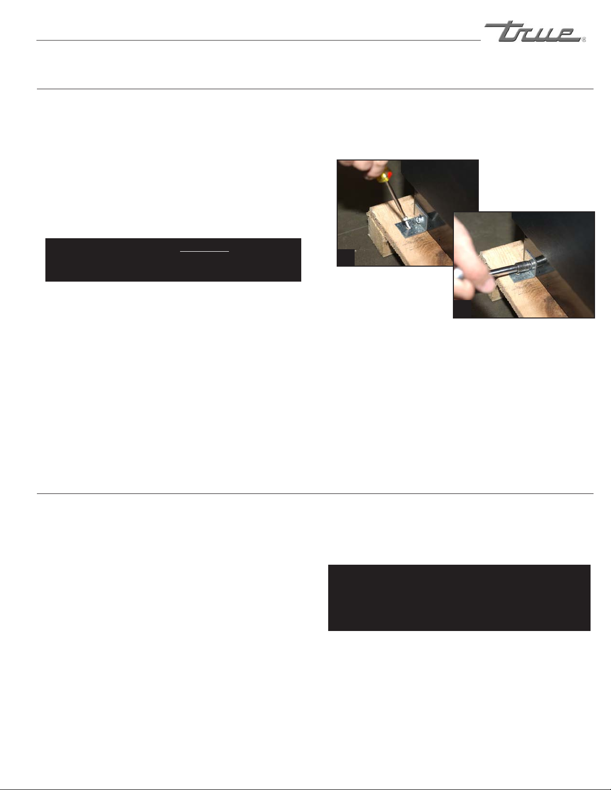
HOW TO CONNECT ELECTRICITY
Hard wiring is required on standard "Dry" Display Cases.
Optional 12" (30.5 cm) corded model available, factory installed only
(exterior scale receptacle will not be included with this option).
WARNING!
NOTE
Applies to models ordered with 12" power
cord, hard wired models do not use this
receptacle.
USE OF ADAPTER PLUGS
NEVER USE AN ADAPTER PLUG! Because of potential safety hazards under certain conditions, we strongly recommend
against the use of an adapter plug.
SAFETY INFORMATION
NEMAplugs
TRUEusesthesetypesofplugs.If
youdonothavetherightoutlethave
acertifiedelectricianinstallthecorrect
power source.
115/60/1
NEMA-5-15R

............ www.truemfg.com ............
True Food Service Equipment, Inc.
4 4
INSTALLATION / OPERATION INSTRUCTIONS
Toinsurethatyourunitworksproperlyfromthefirst
day,itmustbeinstalledproperly.Wehighlyrecommend
atrainedmechanicandelectricianinstallyourTRUE
equipment.Thecostofaprofessionalinstallationis
moneywellspent.
BeforeyoustarttoinstallyourTRUEunit,carefully
inspectitforfreightdamage.Ifdamageisdiscovered,
immediatelyfileaclaimwiththedeliveryfreightcarrier.
TRUE is not responsible for damage incurred during
shipment.
OWNERSHIP
• TinSnips/BandCutters
• ClawHammer
• HexHeadDriver
• AdjustableWrench
• 3/4"(19mm)Open-EndWrench
• PhillipsHeadScrewdriver
• Level
REQUIRED TOOLS
Thefollowingprocedureisrecommendedforuncrating
the unit:
A. Cutmetalretainingstrapssecuringprotectivetop
skid.Removetheouterpackagingbypullingtri-wall
nailsfromskid.Remove(4)cardboardcornerpads
and dust cover.
B. Inspectforconcealeddamage.Again,immediately
fileaclaimwiththefreightcarrierifthereisdamage.
C. Moveyourdisplaycaseasclosetothefinallocation
aspossiblebeforeremovingthewoodenskid.
UNCRATING
INSTALLATION / OPERATION INSTRUCTIONS

............ www.truemfg.com ............
True Food Service Equipment, Inc.
55
INSTALLATION / OPERATION INSTRUCTIONS
TOOLS REQUIRED:
•Phillipsscrewdriver
•3/8”(9.5mm)socketor3/8”(9.5mm)wrench
A. UseaPhillipsscrewdiverandremovefourscrews
fromtheL-bracketconnectedtheunittothewood
skid(image1).Thenusea3/8”(9.5mm)socket
orwrenchandremovetheL-bracketfromtheunit
(image2).
ToavoiddamagetoglassDONOTlaycabinet
onitssideorbackwhenremovingskid,
installingleglevelers,cleaning,etc.
B. Liftupfromthebaseandwalkunitofftheskidand
setinfinallocation.
C. Unblockdoors,(freeplasticwedges,bluefoamand
tape.Removefiberglasstapesecuringglass.
Removecomponents:(shelves,brackets,etc.)from
insidecabinet.
LOCATING
A. Setunitinitsfinallocation.
B. ProperlevelingofyourTRUEunitiscriticalto
operatingsuccess(fornon-mobilemodels).Effective
dooroperationwillbeeffectedbyleveling.
WARNING
Display case must be leveled accurately to ensure front
glass door seals properly.
C. Theunitshouldbeleveledfronttobackandsideto
sidewithalevel.Placethelevelintheinteriorfloorof
theunitandcheckallfoursides.
D. Ifthecabinetisnotleveladjustleglevelersbyfirst
relievingweighttolevelerandadjustingbyeither
handorwrench.Repeatwithallleglevelersuntil
cabinetislevelinalldirections.
Drybakerycasesrequirehardwiringunless
orderedwith12"(30.5cm)cordoption.
CabinetwarrantiesarevoidifOEMpowercordis
tamperedwith.TRUEwillnotwarrantyanyunits
thatareconnectedtoanextensioncord.
LEVELING
Removing bracket from skid.
1
2
Removing bracket from cabinet.

............ www.truemfg.com ............
True Food Service Equipment, Inc.
6 6
INSTALLATION / OPERATION INSTRUCTIONS
NOTE
Hard wiring is required on standard "Dry" Bakery Cases.
NOTE
Optional 12" (30.5 cm) corded model available, factory
installed only (exterior scale receptacle will not be included
with this option).
A. Beforeyournewunitisconnectedtoapowersupply,
checktheincomingvoltagewithavoltmeter.If
anythinglessthan100%oftheratedvoltagefor
operationisnoted,correctimmediately.
Refertocabinetdataplateforvoltage.
TRUErequiresthatasoleusecircuitbededicated
fortheunit.
WARNING
If your bakery case includes optional 12" (30 cm) power
supply cord, ground should not be removed!
NOTE
To reference wiring diagram - wiring diagram is positioned
on the ballast box inside lower rear of the cabinet.
ELECTRICAL INSTRUCTIONS
A. Verifythatthecabinetlightsareworking.Bakery
casesareshippedwithlightswitchesinthe"on"
position.Thetoggleswitchislocatedlowerright
corer at the rear.
REPLACEMENT PARTS
TRUE maintains a record of the cabinet serial number for
your unit. If at any time during the life of your display case,
a part is needed, you may obtain this part by furnishing
the model number and serial number to the company from
whom you purchased the cabinet. Call Toll-Free: (800)-424-
TRUE (Direct to Parts Department). (800)-325-6152 (U.S.A.
& Canada only) or call: (636)-240-2400.
STARTUP
NON-REFRIGERATED "DRY" CURVED GLASS
DISPLAY CASES
(hard wired models only)
HardwiredBakeryCasesareequippedwith
aservicereceptacle(foundontheupperright
cabinetbackside).Noelectricalloadgreater
than4.0ampsshouldbeconnectedtoit.

............ www.truemfg.com ............
True Food Service Equipment, Inc.
77
INSTALLATION / OPERATION INSTRUCTIONS
CONDUCTORS AND CIRCUITS
Wire Guage for 2% Voltage Drop in Supply Circuits.
115 Volt Distance In Feet To Center of Load
Amps 20 30 40 50 60 70 80 90 100 120 140 160
2 14 14 14 14 14 14 14 14 14 14 14 14
3 14 14 14 14 14 14 14 14 14 14 14 12
4 14 14 14 14 14 14 14 14 14 12 12 12
5 14 14 14 14 14 14 14 12 12 12 10 10
6 14 14 14 14 14 14 12 12 12 10 10 10
7 14 14 14 14 14 12 12 12 10 10 10 8
8 14 14 14 14 12 12 12 10 10 10 8 8
9 14 14 14 12 12 12 10 10 10 8 8 8
10 14 14 14 12 12 10 10 10 10 8 8 8
12 14 14 12 12 10 10 10 8 8 8 8 6
14 14 14 12 10 10 10 8 8 8 6 6 6
16 14 12 12 10 10 8 8 8 8 6 6 6
18 14 12 10 10 8 8 8 8 8 8 8 5
20 14 12 10 10 8 8 8 6 6 6 5 5
25 12 10 10 8 8 6 6 6 6 5 4 4
30 12 10 8 8 6 6 6 6 5 4 4 3
35 10 10 8 6 6 6 5 5 4 4 3 2
40 10 8 8 6 6 5 5 4 4 3 2 2
45 10 8 6 6 6 5 4 4 3 3 2 1
50 10 8 6 6 5 4 4 3 3 2 1 1
Wire Guage for 2% Voltage Drop in Supply Circuits.
230 Volt Distance In Feet To Center of Load
Amps 20 30 40 50 60 70 80 90 100 120 140 160
5 14 14 14 14 14 14 14 14 14 14 14 14
6 14 14 14 14 14 14 14 14 14 14 14 12
7 14 14 14 14 14 14 14 14 14 14 12 12
8 14 14 14 14 14 14 14 14 14 12 12 12
9 14 14 14 14 14 14 14 14 12 12 12 10
10 14 14 14 14 14 14 14 12 12 12 10 10
12 14 14 14 14 14 14 12 12 12 10 10 10
14 14 14 14 14 14 12 12 12 10 10 10 8
16 14 14 14 14 12 12 12 10 10 10 8 8
18 14 14 14 12 12 12 10 10 10 8 8 8
20 14 14 14 12 10 10 10 10 10 8 8 8
25 14 14 12 12 10 10 10 10 8 8 6 6
30 14 12 12 10 10 10 8 8 8 6 6 6
35 14 12 10 10 10 8 8 8 8 6 6 5
40 14 12 10 10 8 8 8 6 6 6 5 5
50 12 10 10 8 6 6 6 6 6 5 4 4
60 12 10 8 6 6 6 6 6 5 4 4 3
70 10 10 8 6 6 6 5 5 4 4 2 2
80 10 8 8 6 6 5 5 4 4 3 2 2
90 10 8 6 6 5 5 4 4 3 3 1 1
100 10 8 6 6 5 4 4 3 3 2 1 1

............ www.truemfg.com ............
True Food Service Equipment, Inc.
8 8
INSTALLATION / OPERATION INSTRUCTIONS
SHELVING INSTALLATION ("DRY" bakeRY)
SHELF INSTALLATION:
A. Lifteachdoorupandoutoftrack(donotdisconnect
elastictubing).Stretchelasticsurgicaltubingandset
doorsoneachsideofunit.
B. Locatebrackets,lights,shelves,etc.fromcabinet
interior.
C. Locateshelfsupportswrappedinmicrofoamand
install teeth end into stainless pilasters located on
interiorwalls.Adjusttodesiredheightmatchingright
andleftpairs.(images1&2).
D. Locatethreehorizontallightswrappedinmicrofoam
andinstall(lightsidedown).Electricalcordsshould
beontherighttoplugintosidereceptacles.
Hangendhooksoflightassemblyontwoshelfsup-
ports(leftandright)slideassemblyforwarduntilit
seatsinfrontnotchofshelfsupport.(image3).
E. Installrearbracketsbyslidingendhooksoverrear
notchofshelfsupport.(image4).
F. Locateshelves,installtopshelffirst.Withthefront
lip(traystop)upandtowardscabinetfront,placeon
topoffrontlightassemblyandsnapshelfinto(2)
clipsontopofrearbracket(image5).
G. Plugtoplightassemblyintotopreceptacleofcabinet
interiorsidewall(image5).
H. Repeatproceduresforremainingtwoshelves
(image6).
I. Replace doors in track.
4
5
6
3
2
1
➟
Install shelf supports. teeth
end into stainless pilasters.
Adjust to desired height matching right and
left pairs.
Hang end hooks of light assebly
on front notch of shelf supports.
Install rear brackets.
Snap shelf into position.
Completed assembly.
WARNING
Shelf mounted lighting requires a
closed circuit. All plugs must be
plugged into side wall receptacles for
lights to work. If less than three shelves
are installed be sure attached caps are
plugged into receptacle(s) (image 7).
Shelf plug.
Receptacle
cap.
7

............ www.truemfg.com ............
True Food Service Equipment, Inc.
99
INSTALLATION / OPERATION INSTRUCTIONS
CASTOR INSTALLATION:
TOOLS REQUIRED:
•Castorwrench(ifnotincludedcontactTRUE)
•Adjustablewrench
NOTE
Castors not available for hard wired models.
WARNING
Make sure unit is empty of all its contents (shelving,
shelving lighting). Make sure power supply has been dis-
connected.
A. Curvedglasscanbedamagedifyoulayunitonits
back,side,orfront.Usea6"x6"(15.2cmx15.2
cm)blockofwoodorequivalent.Slidetheblock
underthecabinetframerail.Thiswillsupportthe
unitwhileinstallingcastors.
B. Leglevelerscanbebackedoutbyhand(image1).
C. Taketwothreadedcastorsandthreadtheminto
theexistingleglevelerholes.(image2).Shimscan
beusedbetweencastorandcabinetframerailfor
leveling(image3).Usethetoolprovidedtotighten
thethreadedcastors(image4).
D. Repeatprocessfortheothersideofthecabinet.
WARNING
Display case must be leveled accurately to ensure front
glass door seals properly.
E. Theunitshouldbeleveledfronttobackandside
tosidewithalevel.Placethelevelintheinterior
flooroftheunit
andcheckallfour
sides.
OPTIONAL (installing optional castoRs foRmoDels with 12" coRD option onlY)
Back out leg levelers by hand,
or with adjustable wrench.
Thread castors into existing leg leveler holes.
Tighten castor in position with
castor wrench.
1
2
3
4Use shims as necessary to level cabinet.

............ www.truemfg.com ............
True Food Service Equipment, Inc.
10 10
INSTALLATION / OPERATION INSTRUCTIONS
FORMICA KIT INSTALLATION:
FORMICA KIT COMPONENTS:
(2) FormicaTop EndPanels103/4"wx33"h
(27.3cmx83.8cm).
(2) BottomEndPanels
(1)leftside,(1)rightside(Formicagluedto
blackplasticpanelwith4keyholeslots).
(1) FormicaFrontPanel
widthwillvaryx75/8"h(19.4cm)
NOTE
Please use care when installing the Formica. Formica can
chip, crack, or break.
NOTE
Refer to image 1 for placement of Formica panels.
A. InstallthefrontFormicapanel.
Besurebottomendpanelsareoffinorderto
installfrontpanel.Slidefrontpanelintotopand
bottomtracksonthefrontofthecabinet.Make
surepanelisevenonbothleftandrightendofthe
cabinet(images1&2).
B. Install the top end Formica panels (one on each
side.
Besurebottomendpanelsare
offinordertoinstalltopend
Formica panel. Both top end
panelsarethesamesizesothey
eachcanbeusedforleftorrightof
thecabinet.
Slidepanelupintoblackplastictracksonthetop
sidepanelofeachendofcabinet(images1&3).
NOTE
After installing the bottom end pieces the top end panel
will stay in place.
C. InstallthebottomendFormicapanels(oneon
each side.
(Formicaispre-gluedtoblackplasticpanel).
Lineupthefourkeyholeslotsineachbottomend
piecetothe(4)screwsonthesideofthecabinet.
Slipthe(4)largekeyholesfromthebottomend
pieceoverthe(4)screws.Thenpushdowntofas-
tenthebottomendpieceontothecabinet(images
1&3).
NOTE
The bottom left and right pieces are not the same. The
taller part of the bottom end piece goes to the rear of the
cabinet as shown in image 3.
OPTIONAL (installing optional foRmica kit)
3
1
2
Four keyholes on
backside.
Formica top
end panel will
slide up into
plastic tracks.
Formica top
end panel will
rest on screw.
Formica bottom end
panel will lock through
keyholes on backside
of bottom end piece.
STEP A
Side view of Formica sliding into place for
front panel and top end panel.
STEP C
STEP B
STEP A
Tracks to hold
Formica.
Formica.

............ www.truemfg.com ............
True Food Service Equipment, Inc.
11 11
MAINTENANCE, CARE & CLEANING
• Theexteriormaybewipedcleanwithmildsoapand
water.Useagoodstainlesscleaneroncountertop.
CAUTION
Do not use any steel wool, abrasive or chlorine based prod-
ucts to clean stainless steel surfaces.
• Theinteriorofthedisplaycaseshouldbecleaned
periodicallyandwerecommendamildsolutionof
dilutedbakingsodaandwaterwhichwillhelpreduce
anyinherentodors.Donotuseharshcleanersonany
surfaceoftheinterior.
CABINET CLEANING
Itmaybenecessarytosealthebakerycasetothefloorfor
localsanitarycodesorifthecustomersodesires.TRUErec-
ommendseitherofthefollowingmethods.
A. Usingavinylcovebasetrimasproducedby
Armstrong, Johnson, or Kentile(availableatfloorcover-
ingsuppliers)or
Usingmasticsavailableathardwarestores.
B. Whenapplyingthecovebasetrim,thoroughlyclean
boththecabinetandfloorofdirtandgrease.Applya
recommendedcontactcementtothecovebasetrim.
Aftercovebasetrimhasdried,fillincracksandjoints
withacaulkingmaterial.
C. Whenapplyingamastic,thoroughlycleanboththe
cabinetandfloorofdirtandgrease.Drawanoutline
ofthecabinetonthefloor.Raiseandblockthefront
sideofthecabinet.Applyabeadofmastictothefloor
1/2"(1.3cm)insidetheoutlinedrawn.Lowerthe
cabinet.Raiseandblocktherearsideofthecabinet.
Applythebeadofmastic,lowerthecabinet.
OPTIONAL (sealing cabinet to flooR)

............ www.truemfg.com ............
True Food Service Equipment, Inc.
12 12
MAINTENANCE, CARE & CLEANING
LIGHT BULB REPLACEMENT
SHELF MOUNTED BULB REPLACEMENT:
WARNING
When replacing a light bulb make sure power to the unit
is either turned off or unplugged.
A. Unplugthelightassemblyfromthereceptacle
ontheinteriorsidewall.Removeshelfandlight
assemblyfromcabinet.
B. Removethelampshieldbygentlysqueezingthe
sidestogetherandrotatingout(image1).
C. Removebulbfromthecordedendofassemblyby
holdingthebulbandgentlypullinguponspring
loadedlampholderwhichwillallowenoughclear-
ancetoremovebulb(image2).
NOTE
All spring loaded lampholders are located on the left side
of the cabinet as you face the front.
NOTE
Please be aware of your local ordinances for disposal of
old florescent bulbs. These bulbs should be disposed of in
a safe and proper manner.
D. Installnewbulbusingspringloadedlampholder.
E. Reinstalllightassemblyandshelf.Plugcordinto
side wall receptacle.
INTERIOR TOP BULB REPLACEMENT:
WARNING
When replacing a light bulb make sure power to the unit
is either turned off or unplugged.
A. Removethelampshieldbygentlysqueezingthe
sidestogetherandrotatingout(image3).
B. Removebulbbygentlypushingbulbbackinto
springloadedlampholderwhichwillallowenough
clearancetoremovebulb(image4).
C. Installnewbulbusingspringloadedlampholder.
D. Reinstalllightlampshieldbyslidingrear"U"chan-
neloflampshieldovermetalbracketandgently
squeezinglampshieldtofitfront"U"channelover
frontmetalbracket(images5-6).
E. Image7showsassemblyproperlyinstalled.
4
56
3
2
1
➟
7
➟
➟
➟
Squeezelampshieldand
rotate out.
Remove bulb by gently
pulling up on spring loaded
lampholder.
Squeeze lampshield and
rotate out. Remove bulb by gently pushing bulb
into spring loaded lampholder.
Squeeze lampshield "U"
channel into position
over metal bracket.
lampshield "U" channel
in position over metal
bracket.
Interior top light assembly
properly installed.
➟

............ www.truemfg.com ............
True Food Service Equipment, Inc.
13 13
WARRANTY INFORMATION (U.S.A. and Canada ONLY!)
note: warranty information regarding refrigeration components not applicable to non-refrigerated cabinets.
ONE YEAR PARTS & LABOR WARRANTY
TRUE warrants to the original purchaser of every new TRUE refrigerated unit, the cabinet and all parts thereof, to be free from defects in material or
workmanship, under normal and proper use and maintenance service as specified by TRUE and upon proper installation and start-up in accordance with
the instruction packet supplied with each TRUE unit. TRUE’s obligation under this warranty is limited to a period of one (1) year from the date of original
installation or 15 months after shipment date from TRUE, whichever occurs first.
Any part covered under this warranty that are determined by TRUE to have been defective within one (1) year of original installation or fifteen (15)
months after shipment date from manufacturer, whichever occurs first, is limited to the repair or replacement, including labor charges, of defective parts or
assemblies. The labor warranty shall include standard straight time labor charges only and reasonable travel time, as determined by TRUE.
ADDITIONAL FOUR YEAR COMPRESSOR WARRANTY
In addition to the one (1) year warranty stated above, TRUE warrants its hermetically and semi-hermetically sealed compressor to be free from
defects in both material and workmanship under normal and proper use and maintenance service for a period of four (4) additional years from the date of
original installation but not to exceed five (5) years and three (3) months after shipment from the manufacturer.
Compressors determined by TRUE to have been defective within this extended time period will, at TRUE’s option, be either repaired or replaced with
a compressor or compressor parts of similar design and capacity.
The four (4) year extended compressor warranty applies only to hermetically and semi-hermetically sealed parts of the compressor and does not
apply to any other parts or components, including, but not limited to, cabinet, paint finish, temperature control, refrigerant, metering device, driers, motor
starting equipment, fan assembly or any other electrical component, etcetera.
404A/134A COMPRESSOR WARRANTY
The four year compressor warranty detailed above will be voided if the following procedure is not carefully adhered to:
1. This system contains R404A or R134A refrigerant and polyol ester lubricant. The polyol ester lubricant has rapid moisture absorbing qualities. If
long exposure to the ambient conditions occur, the lubricant must be removed and replaced with new. For oil amounts and specifications please call TRUE
technical service department (800-325-6152). Failure to comply with recommended lubricant specification will void the compressor warranty.
2. Drier replacement is very important and must be changed when a system is opened for servicing. A drier using XH-7 desiccant or an exact
replacement solid core drier must be used. The new drier must also be the same capacity as the drier being replaced.
3. Micron level vacuums must be achieved to insure low moisture levels in the system. 500 microns or lower must be obtained.
WARRANTY CLAIMS
All claims for labor or parts must be made directly through TRUE. All claims should include: model number of the unit, the serial number of the
cabinet, proof of purchase, date of installation, and all pertinent information supporting the existence of the alleged defect.
In case of warranty compressor, the compressor model tag must be returned to TRUE along with above listed information.
Any action or breach of these warranty provisions must be commenced within one (1) year after that cause of action has occurred.
WHAT IS NOT COVERED BY THIS WARRANTY
TRUE’s sole obligation under this warranty is limited to either repair or replacement of parts, subject to the additional limitations below. This warranty
neither assumes nor authorizes any person to assume obligations other than those expressly covered by this warranty.
NO CONSEQUENTIAL DAMAGES. TRUE IS NOT RESPONSIBLE FOR ECONOMIC LOSS; PROFIT LOSS; OR SPECIAL, INDIRECT, OR
CONSEQUENTIAL DAMAGES, INCLUDING WITHOUT LIMITATION, LOSSES OR DAMAGES ARISING FROM FOOD OR PRODUCT SPOILAGE CLAIMS
WHETHER OR NOT ON ACCOUNT OF REFRIGERATION FAILURE.
WARRANTY IS NOT TRANSFERABLE. This warranty is not assignable and applies only in favor of the original purchaser/user to whom delivered.
ANY SUCH ASSIGNMENT OR TRANSFER SHALL VOID THE WARRANTIES HEREIN MADE AND SHALL VOID ALL WARRANTIES, EXPRESS OR IMPLIED,
INCLUDING ANY WARRANTY OF MERCHANTABILITY OR FITNESS FOR A PARTICULAR PURPOSE.
IMPROPER USAGE. TRUE ASSUMES NO LIABILITY FOR PARTS OR LABOR COVERAGE FOR COMPONENT FAILURE OR OTHER DAMAGES
RESULTING FROM IMPROPER USAGE OR INSTALLATION OR FAILURE TO CLEAN AND/OR MAINTAIN PRODUCT AS SET FORTH IN THE WARRANTY
PACKET PROVIDED WITH THE UNIT.
ALTERATION, NEGLECT, ABUSE, MISUSE, ACCIDENT, DAMAGE DURING TRANSIT OR INSTALLATION, FIRE, FLOOD, ACTS OF GOD. TRUE is
not responsible for the repair or replacement of any parts that TRUE determines have been subjected after the date of manufacture to alteration, neglect,
abuse, misuse, accident, damage during transit or installation, fire, flood, or act of God.
IMPROPER ELECTRICAL CONNECTIONS. TRUE IS NOT RESPONSIBLE FOR THE REPAIR OR REPLACEMENT OF FAILED OR DAMAGED
COMPONENTS RESULTING FROM ELECTRICAL POWER FAILURE, THE USE OF EXTENSION CORDS, LOW VOLTAGE, OR VOLTAGE DROPS TO THE
UNIT.
NO IMPLIED WARRANTY OF MERCHANTABILITY OR FITNESS FOR A PARTICULAR PURPOSE: THERE ARE NO OTHER WARRANTIES,
EXPRESSED, IMPLIED OR STATUTORY, EXCEPT THE ONE (1) YEAR PARTS & LABOR WARRANTY AND THE ADDITIONAL FOUR (4) YEAR
COMPRESSOR WARRANTY AS DESCRIBED ABOVE. THESE WARRANTIES ARE EXCLUSIVE AND IN LIEU OF ALL OTHER WARRANTIES, INCLUDING
IMPLIED WARRANTY AND MERCHANTABILITY OR FITNESS FOR A PARTICULAR PURPOSE. THERE ARE NO WARRANTIES WHICH EXTEND BEYOND
THE DESCRIPTION ON THE FACE HEREOF.
OUTSIDE U.S.: This warranty does not apply to, and TRUE is not responsible for, any warranty claims made on products sold or used outside the
United States.
REMOTE CONDENSERS: TRUE warrants the original purchaser of the remote cabinet one year parts and labor coverage for all cabinet parts thereof
to be free from defects in material or workmanship, under normal and proper use and maintenance service, as specified by TRUE. This warranty is limited
to the cabinet only. TRUE assumes no liability for remote condensing units.
This manual suits for next models
1
Table of contents
Other True Manufacturing Company Display Case manuals
Popular Display Case manuals by other brands

Choice
Choice 176BDC3 Assembly instructions

Goldmedal
Goldmedal 5580BV4 instruction manual

Alto-Shaam
Alto-Shaam HALO HEAT ED2-60 Installation operation & maintenance

Tecnodom
Tecnodom VULCANO User and maintenance manual

Oscartielle
Oscartielle MARTE Series instruction manual

SEGUE
SEGUE VK-1314 Setup instructions