Hosiden Besson Banshee Excel IS28 MK6 User manual

Banshee Excel IS28 MK6
Audible Warning Device

Banshee Excel IS28 MK 6 Audible Warning Device PK01334 A
This product has been assessed to conform to the ATEX Directives and certified under IECEx scheme. It
has the following approval identifications.
Instructions for use
The IS 28 Banshee is intended for use in locations that are considered to present a risk due to the presence
of flammable gases, vapours and explosive dust atmospheres.
Marking
The product is marked with a label on the outside giving details of manufacturer, model name, category of
hazardous protection provided, details of limiting design parameters and a statement about minimising any
electrostatic hazard.
Inside the Banshee sounder is another label. This shows the location of the volume control, the name of
the product and the approving authority and number.
The text shows that the apparatus is intended to conform to requirements of Intrinsic Safety operation with
2 faults present in group IIC (Hydrogen) gas environment. The maximum surface temperature of any part
of the Banshee IS28 is assessed not to exceed a T5 (85 degrees C) category in an ambient air temperature
of +70 degrees C. The label further reminds the installer to only connect the sounder via a safety barrier,
and shows the polarity of the supply connection, the DIL Switch to select one of 32 different sounds, See
the Sound Output Table.
1

Sound Output Table
No
Sound Frequencies & Patterns
Code
12345
Description
Typ SPL@1m on
axis dBA
Typ
Current
mA
1
800Hz to 950Hz swept at 120Hz
00000
Banshee Buzz LF
89
12
2
800Hz to 950Hz swept at 9Hz
10000
Banshee Fast Sweep LF
89
12
3
800Hz to 950Hz swept at 3Hz
01000
Banshee Slow Sweep LF
89
12
4
Continuous at 900Hz
11000
Banshee Continuous LF
90
12
5
830Hz to 970Hz swept at 9Hz
00100
Banshee Fast Sweep LF (New)
90
12
6
800Hz to 970Hz swept at 1Hz
10100
Medium Sweep LF
90
12
7
Continuous at 950Hz
01100
Continuous LF
89
12
8
Intermittent at 950Hz 1 sec on, 1
sec off
11100
Back Up Alarm LF
89
12
9
Alternating 800Hz/1000Hz at 1Hz
00010
Alternate LF
88
12
10
800Hz to 1000Hz swept at 0.5
secs
10010
Medium Sweep LF
90
12
11
Alternating Tones 800/950Hz at
3Hz
01010
Alternate LF
89
12
12
2400Hz to 2900Hz at 120Hz
11010
Banshee Buzz HF
97
14
13
2400Hz to 2900Hz at 9Hz
00110
Banshee Fast Sweep HF
98
14
14
2400Hz to 2900Hz at 3Hz
10110
Banshee Slow Sweep HF
98
14
15
Continuous 2900Hz
01110
Banshee Continuous HF
97
14
16
2450Hz to 3100Hz swept at 9Hz
11110
Banshee Fast Sweep HF (New)
97
14
17
Intermittent at 2900Hz 1 sec on,
1 sec off
00001
Back Up Alarm HF
97
14
18
Alternating Tones 2400/2900 at
3Hz
10001
Alternate HF
97
15
19
500Hz rising to 1200Hz over 3.5
sec, silence 0.5 sec
01001
Slow Whoop
90
12
20
1200Hz falling to 500Hz over 1
sec, silence 10mS
11001
Din Tone (DK)
89
12
21
554Hz for 100mS and 440Hz for
400mS
00101
French Fire Sounder
86
11
22
420Hz repeating 0.625 sec on,
0.625 sec off
10101
Australian Alert Signal
82
11
23
500Hz to 1200Hz sweeping, 3.75
secs on, 0.25 secs off
01101
Australian Evacuation Signal
90
12
24
950Hz for 0.5 sec on, 0.5 sec off
for 3 phases, silence for 1.5 secs
11101
US Temporal Tone LF
89
12
25
2900Hz for 0.5sec on, 0.5sec off
for 3 phases, silence for 1.5 sec
00011
US Temporal Tone HF
97
14
26
Intermittent 660Hz 150mS on,
150mS off
10011
Swedish Tone (Fire)
80
11
27
Continuous 660Hz
01011
Swedish Tone (All Clear)
81
11
28
Intermittent 970Hz 500mS on,
500mS off
11011
ISO8201 LF
89
12
29
Intermittent 2900Hz 500mS on,
500mS off
00111
ISO8201 HF
97
14
30
Yodel 800Hz/1000Hz, 0.25sec
10111
BT Banshee (FP1063,1)
88
12
31
Continuous 1000Hz
01111
BT Banshee (FP1063,1)
85
12
32
Bell Tone
11111
Bell Tone
90
11
Typical SPL and Current consumption figures when supplied from 24V DC via a 28Volt 300 ohm barrier.
2

DRG NO. 81700
3

Installation
Warning: The sound pressure Level produced by the sounder is loud enough to cause hearing damage if in
close proximity to the sounder.
The IS 28 Banshee is intended to be mounted on a vertical surface using the fixing bracket, and secured
using suitable fixings. It should normally be sited at a height of about 2 to 3 m from the floor surface, to
ensure good sound coverage and without causing unnecessary hearing damage.
This drawing (81700) shows various combinations of options that installer’s may care to use, but it is not
exhaustive. The essence is the cable parameters and the zener barrier sections. Consultation with the
installer’s preferred cable and zener barrier supplier’s, should enable the correct components to be
selected.
Incoming wiring is to be routed directly to the sounder terminal block having checked correct polarity.
Finally with all the wiring correct and tested, the sounder may be refitted to the base, with O-ring in place
and turn clockwise to retain. The whole assembly is locked together by fitting the security screw
(supplied) through the hole in the side of the sounder assembly.
Note: See illustration below for the incorrect / correct alignment marks for fitting both parts together.
If it is required to change the tone or adjust the loudness of the audible tone produced. The sounder must
be removed from the base for this to happen. Ensure all wiring and O-rings are correctly located before the
2 parts are re-assembled.
There are no other user controls or adjustments with the product.
For IP66 Protection
No holes must be made to any part of the Banshee IS28 MK6, except for the base side knock-outs. This
allows fitting of a 20mm gland assembly (Not supplied) that must be suitably sealed to the base for wiring
to pass through to maintain ingress protection. Use wall mounting bracket to fix base to vertical surface. A
spacer is supplied to insure a flat fixing surface for a cable gland if mounted on the single gland entry
point.
4
Incorrect Alignment
Correct Alignment

Maintenance and Servicing
The Banshee IS28 MK6 AWD needs no adjustment, providing the environment it operates in has not
changed. Any such change may mean adjustment to volume control.
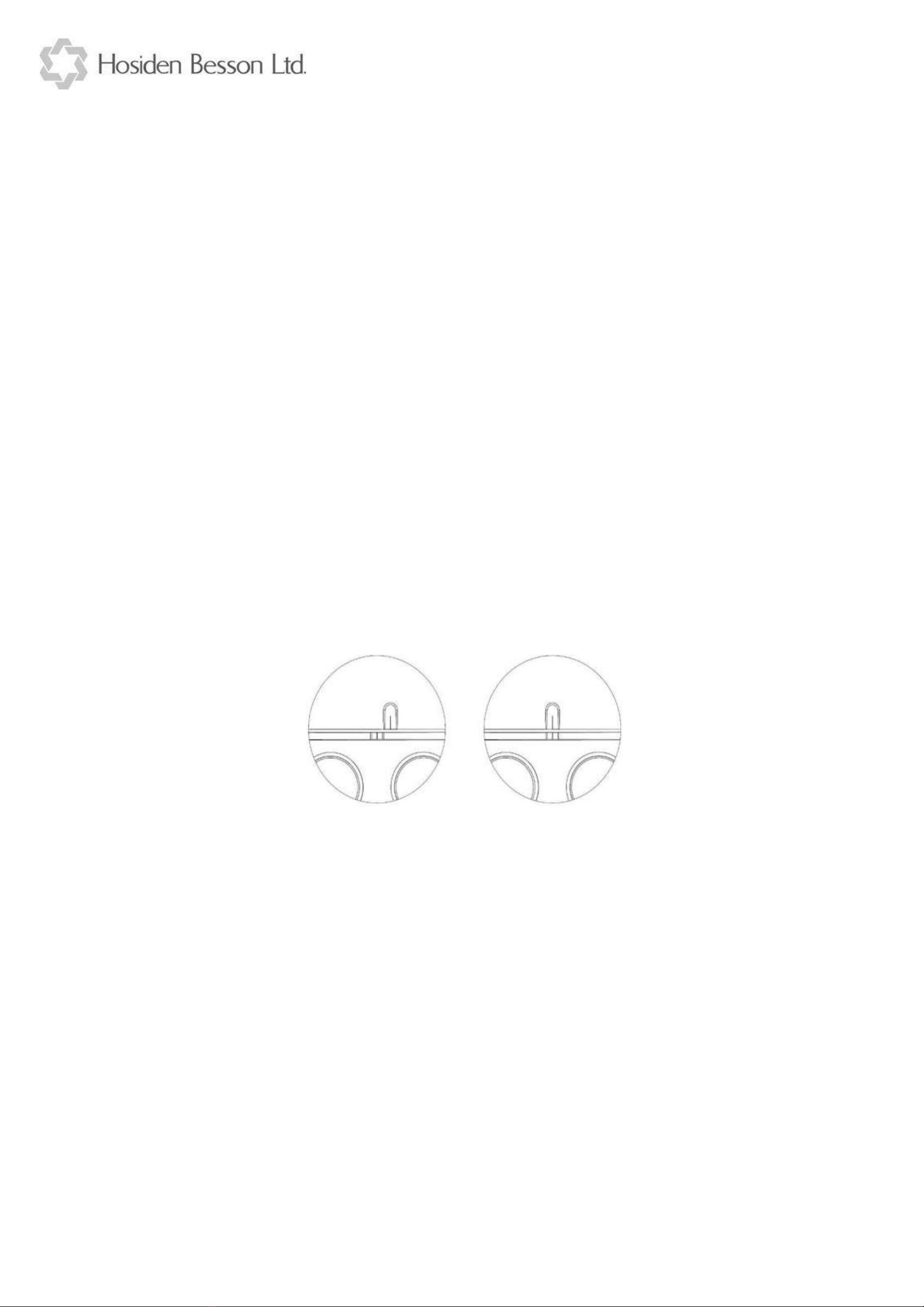
The sounder needs no servicing beyond avoiding the removal of any obstruction to the sound outlet
“nose”. All debris should be removed as soon as possible to avoid loss of sound output.
Water should be allowed to drain from the nose area. The sounder should not been mounted on a
horizontal surface facing up. Any other debris should be gently blown from the nose using low pressure (2
to 5 psi) air. High pressure, (shop) air, may result in debris getting into ‘eyes’ or ‘ears’ etc. of service
personnel, and must not be used for this purpose.
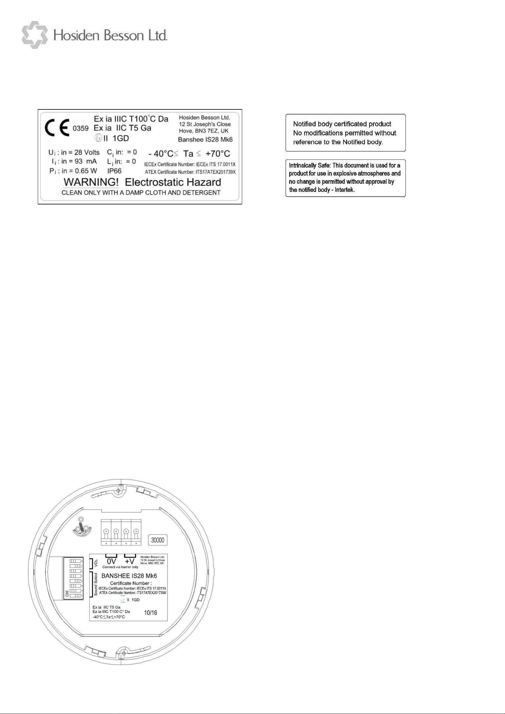
A warning notice on the sounder allows for cleaning of the apparatus, only with a damp cloth, to avoid
any electrostatic hazard from the plastics housings.
No hydro-carbon based solvents should be used as these will cause a chemical reaction with the (ABS)
plastics mouldings, as will any other substance with similar composition.
If the Banshee IS28 MK6 sounder fails to function, there are no user parts to change, the complete product
must be removed from its installation and a replacement sounder obtained and fitted.
Other Notes and warnings
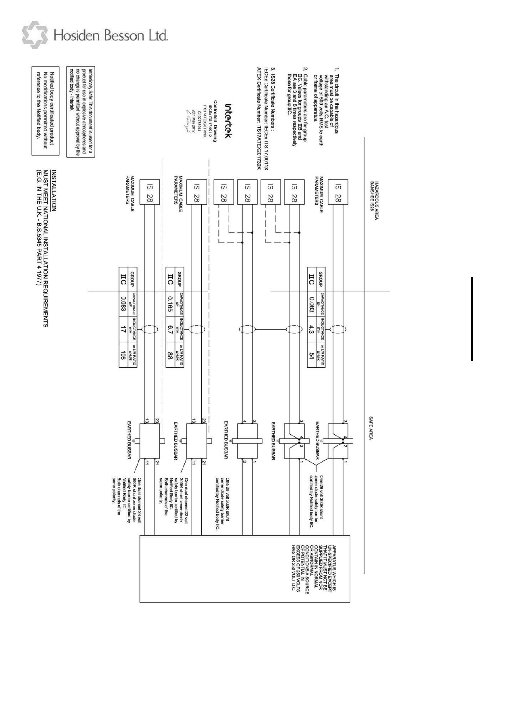
This product is intended for use ONLY with Zener barrier, or similar intrinsic safety protection power
supply device. It is NOT intend for direct connection to “24 volt” fire alarm panels, as the supply voltage
will be too high for safe operation. Also the fire panel is unlikely to be approved for this type of operation.
Simple zener barriers are not suitable for operation from “24 volt” fire alarm panels (as the float charge
voltage can exceed 27 volts dc, which is beyond the maximum rating of this type of barriers).
Some “dc/dc galvanically isolated barriers” may accept input voltages beyond 30 volts dc, and could be
safe to use with the Banshee IS28 MK6. Consult the barrier manufacture for further clarification.
Note however, that these cannot generally be used in “Alarm line monitoring” applications as even if they
support input polarity reversal, they will still require some current to function, when in the line monitor
mode, and this would be seen by the fire alarm panel as a leakage or short circuit condition.
5

6

7

8

9

10

11
Other Hosiden Besson Marine Equipment manuals