Andersen 40 ST FS User manual

MANUAL
40ST – 40 ST FS
Version 3.0 Version 1.0

GENERAL INFORMATION
Due to the best choice of materials and high precision in manufacturing we recommend for
normal use only to dismantle clean and lubricate the winch once every second year. Under
extensive use such as racing charter or blue water sailing we recommend to lubricate the winch
once every year.
We strongly recommend always to use ANDERSEN WINCH GREASE when lubricating your
winch. ANDERSEN WINCH GREASE is a high quality silicone/Teflon grease product.
Most other types of grease including “marine grease” are not suitable for lubrication of winches.
Non-suitable grease products can cause malfunction which could result in fatal injuries for the
user and others.
Pawl arm springs should be replaced every second year. Spare arm springs and other parts that
may be required are included in the ANDERSEN Service Kit. Please refer to the service instruction
for the Service Kit suitable for the specific winch.
When the winch handle is not in use but the winch is under load we recommend from a safety
point of view to remove the winch handle from the winch.
To ensure correct function of the selftailing unit only use recommended line sizes. When using
the winch with mooring lines DO NOT use the selftailing function and be sure that the mooring line
is not in contact with the selftailing arm.
To ensure the best possible functioning of the winch we recommend that the winch is placed in
accordance with the line entry shown below.
Be also aware that selftailing arm is positioned correctly. We recommend to have the selftailing
arm positioned within the shaded area. On 12ST and 28ST the position of the selftailing arm is
fixed making it very important to establish the proper location of the holes prior to drilling these in
the deck. On all other models the selftailing arm can be placed in several different positions after
having installed the winch.

INSTALLATION
Installing the winch is easy if you follow these instructions. The numbers in ( ) refer to the position
numbers in the parts list.
Tools required for the installation:
Screwdriver (large).
Ø6 5 mm. (1/4”) drill.
5 pcs. M6 (1/4”) countersunk head screws.
Ring spanner to match nuts.
1. Drill bolt holes Ø6 5mm (1/4”) using the winch template. Be sure that no dust comes in
contact with the winch while drilling.
2. Remove screw (1) and top cap (2).
3. Remove selftailing arm (3) and drum (5).
4. Apply a light coat of bedding compound on the bottom of the base (20). Ensure that each bolt
hole is bedded. Keep drain grooves clear.
5. Fasten base (20) into place using 5 pcs. M6 (1/4”) countersunk head screws. Use large
washers or a backing plate.
6. Assemble in reverse order.
7. Check that the winch is functioning correctly:
The drum should operate smoothly by turning the drum clockwise by hand.
The drum must not turn when trying to turn the drum anti clockwise.
While turning the winch handle clockwise the drum should turn fast.
While turning the winch handle anti clockwise the drum should turn slowly.

SERVICE INSTRUCTION
Tools required for service:
Screwdriver (large).
Screwdriver (small).
Winch handle.
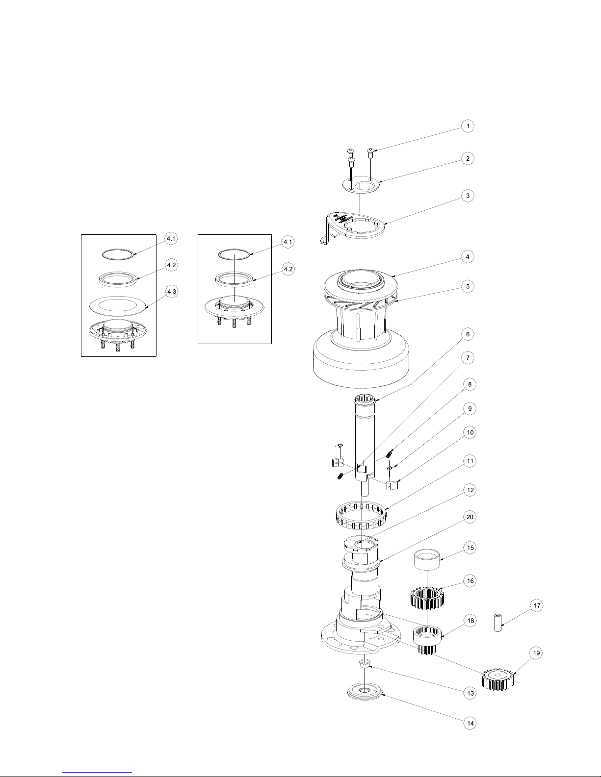
1. Remove screw (1) and top cap (2).
2. Remove self-tailing arm (3) and drum (5).
3. Insert a winch handle. Pull up the drive shaft (6) gently while turning gear wheel (19) and
ratchet gear (16) carefully. Remove drive shaft (6).
4. Remove lower pawls (10) arm springs (9) and springs (8). The upper pawls are not
removable.
5. Remove ratchet gear (16) and bushing (15).
6. Remove ratchet gear (18).
7. To release the roller bearing (11) gently insert a small screwdriver between roller bearing
and base (20). Remove roller bearing (11).
8. Remove shaft (17) and gear wheel (19). Use a screwdriver.
9. Clean all parts in petrol. Remember to clean the gear teeth.
10. Assemble in reverse order. During assemble lightly grease all gear teeth drive shaft roller
bearing shafts pawls springs and bushings. Use a small soft brush. Pawls may be
lubricated with either a very thin film of ANDERSEN WINCH GREASE. It is very important
that pawls can move freely.
IMPORTANT: When assembling the winch check the functioning of each pawl by pushing the
pawl against the spring. The pawls should move smoothly and automatically return to their normal
position where the pawls engage with the teeth. If the pawls do not function correctly clean and
lubricate the pawls and gears. Check the function of the pawls again to make sure that it works
correctly. If the pawls do not work correctly replace the springs and recheck the functioning.
Not properly functioning pawls may lead to unexpected release of the winch force resulting in fatal
injuries to the user and others.
Service Kit No: 1 (art. no. 710018) contains spare parts for this winch.

PARTS LIST
POS QTY DESCRIPTION ART NO
1. 3 Screw ISO 7380-A4-M6x12
2. 1 Top cap 535101
3. 1 Selftailing arm 535220
4. 1 Selftailing Top Model ST - 537450 / ST FS - 537410
4.1 1 Circlip 590300U
4.2 1 Top Ring 782220
4.3 1 Disc Model ST only - 535510
5. 1 Drum cpl. 535411
6. 1 Drive shaft cpl. 535300
7. 2 Pawl special Not remove able 729300
8. 2 Spring 533500
9. 2 Arm spring 713300
10. 2 Pawl 713200
11. 1 Roller bearing cpl. 727400
12. 2 Bushing Not remove able 716501
13. 1 Bushing 536300
14. 1 Retaining Ring 536200
15. 1 Bushing 536000
16. 1 Ratchet gear 711701
17. 1 Shaft 536400
18. 1 Ratchet gear 536100
19. 1 Gear Wheel 729603
20. 1 Base 741210
1 Service kit, consist of pos 710018

EXPLODED VIEW
POS. 4 - 537450 POS.4 - 537410
This manual suits for next models
1
Table of contents
Other Andersen Marine Equipment manuals
Popular Marine Equipment manuals by other brands

CPT AUTOPILOT
CPT AUTOPILOT Wheel Pilot Operation manual

System Sensor
System Sensor B501BHT-2 Installation and maintenance instructions

AMC
AMC ISIDE 130 Handbook

DS18
DS18 MRX100 owner's manual

Haiyang
Haiyang HIS-700R Quick instructions

EMBRON
EMBRON Hatteland Display Maritime Multi Computer X... user manual