Veethree T Series User manual

INSTALLATION MANUAL
/for installing Veethree displays

2
veethree.com
Telephone:
Europe & Worldwide +44 (0) 1202 973 023
USA & Canada +00 1 941 538 7775
Email:
International Sales Team – info@veethree.com
USA Sales Team – sales@veethree.com

3veethree.com/support/templates/
Installation Manual
CONTENTS:
/T-Series - Touch screen colour displays 18
/R-Series - Round housing displays 10
/C-Series - Colour displays 11
/M-Series - Monochrome displays 13
1: Mounting the display
page ... 4
2: Connecting your display
page ... 6
3: Maintenance and troubleshooting
page ... 7
4: Connectors
page ... 8
5: Safety information
page ... 13

4Installation Manual
Display Mounting
Units are designed to be mounted onto a bulkhead, dashboard, or panel. The method is
described below. The only required components are the mounting bracket and hardware.
Allow adequate clearance behind the display for cable connection (to ensure that the
cables are not unduly stressed), and for ventilation. Leave sufficient cable so that the
unit may be removed for servicing
Screw the threaded studs into the rear case
Carefully cut out the mounting hole, templates are available upon request if required
Place the CANvu Display in position, use the mounting bracket and™ thumb nuts to
secure the units. The thumb nuts should only be hand tight
In the correct order connect the Deutsch mating connector harness into the housing,
ensuring it is fully seated
1. Mounting the display
Instructions
WARNING:
Do not over tighten the studs/thumb nuts and don’t use metal
screws as they may damage the unit and void the warranty.

5veethree.com/support/templates/
Typical mounting method
Mounting templates can be downloaded
from our website at
veethree.com/support/templates/
”) x ”)
”) x ”)
70mm (2.75”) x 70mm (2.75”)
Cut Out for back recess 86mm
diameter (3.39”)
Drill 4mm clearance x 4 = 4.3mm (0.17”)
mm
”)
= 4.3mm (0.17”)
”) x ”)
”) x ”)
70mm (2.75”) x 70mm (2.75”)
”)
= 4.3mm (0.17”)
Cut Out for back recess 86mm
diameter (3.39”)
Drill 4mm clearance x 4 = 4.3mm (0.17”)
Fixing Template
Overall size 95mm (3.74”) x 95mm (3.74”)
Fixing Hole Positions 70mm (2.75”) x 70mm (2.75”)

6Installation Manual
The displays should be installed and setup in accordance to this manual by a
competent individual who is used to working with electrical systems. Failure to follow
these instructions may result in malfunction and in-validate any warranty.
2.1 No power should be present on the harness during connection.
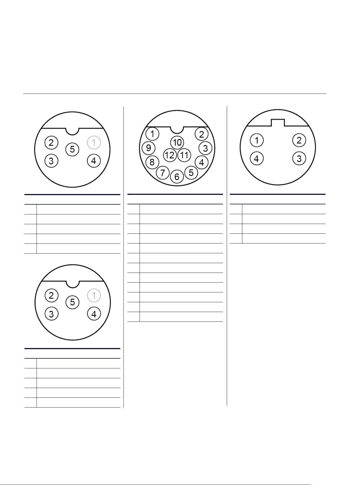
2.2 Connect Harness 1 (Primary) note correct orientation of connector. Ensure it is
fully mated so the connector latches into place.
2.3 Then connect Harness 2 (Secondary) note correct orientation of connector.
Ensure it is fully mated so the connector latches into place when using dual
and triple harness models.
2.4 The USB ports should not be used for charging external equipment such as
mobile phones.
Please refer to the following images below for harness connection order.
Connecting to the Network
The range of displays will operate with a number of CAN network protocols. If you are
unsure of which CAN networks are supported, please contact Veethree for advice.
Please consult relevant network protocol standards to ensure that the unit is
connected correctly. Ensure that the power is off during any connection being made
and you are observing connecting the device in section 1.
Veethree can offer support, if you need any further help or guidance on your particular
network topography.
2. Connecting your display
IMPORTANT NOTE:
Safety Warning: Please note analogue input voltages should not
exceed the supply voltage or damage may occur.

7veethree.com/support/templates/
No regular maintenance should be required, except for cleaning the lens as needed, using
a soft, damp cloth. Do not use abrasive materials or solvents.
If you are experiencing operating problems with the display, refer to the following
diagnostics:
3. Maintenance and troubleshooting
Problem Possible Solution
Unit does not power up
Ensure connections to unit are correct
Ensure power source is present
Unit fails to display any data
Ensure connections to unit are correct
Ensure data source is broadcasting data
Ensure source address in the display
matches source data being provided
by the engine and/or transmission
Ensure the backbone is connected and
terminating resistors are in place
Unit displays random data
Ensure connections to unit are correct
Ensure “demo mode” is off

8Installation Manual
4. Connectors
CAN1
1No Connection
2Positive DC Supply
3Ground
4CAN Data H
5CAN Data L
T7i
CAN2
1No Connection
2Isolated Volts Positive
3Isolated Volts Negative
4Isolated CAN Data H
5Isolated CAN Data L
ETHERNET
1White/Orange +TK
2White/Green +RX
3Orange - TX
4Green
EXTERNAL USB IO
1USB Volts Positive
2USB Data Negative (DM)
3USB Data Positive (DP)
4No Connection
5USB Volts Negative
6RS422/485 Tx+*
7RS422/485 Tx-*
8RS422/485 Rx+*
9RS422/485 Rx-*
10 Digital Input
11 Analogue Input
12 Relay Output
*RS422 and RS485 options
configured as a build option

9veethree.com/support/templates/
CAN1
1No Connection
2Positive DC Supply
3Ground
4CAN Data H
5CAN Data L
T5
CAN2
1No Connection
2Isolated Volts Positive
3Isolated Volts Negative
4Isolated CAN Data H
5Isolated CAN Data L
ETHERNET
1White/Orange +TK
2White/Green +RX
3Orange - TX
4Green
*RS422 and RS485 options con-
figured as a build option
EXTERNAL USB IO
1USB Volts Positive
2USB Data Negative (DM)
3USB Data Positive (DP)
4No Connection
5USB Volts Negative
6RS422/485 Tx+*
7RS422/485 Tx-*
8RS422/485 Rx+*
9RS422/485 Rx-*
10 Digital Input
11 Analogue Input
12 Relay Output

10 Installation Manual
PRIMARY CONNECTOR
1Ground
2Power Input
3Dimmer Input
4Analogue in 1
5CAN Ground
6CAN Power
7NMEA 2000 / J1939 - CAN H
8NMEA 2000 / J1939 - CAN L
9NMEA 0183+ (Differential)
10 NMEA 0183- (Differential)
11 Power Supply (Output for
GPS)
12 Ground Supply (Output for
GPS)
R3
SECONDARY CONNECTOR
1Analogue - Ground
2Digital Out 1 (Relay / Buzzer)
3Analogue in 2
4Analogue in 3
5Analogue in 4
6Analogue in 5
7Analogue in 6
8Digital Input 1
9Digital Input 2
10 Digital Input 3
11 Digital Input 4
12 Frequency Input
PRIMARY CONNECTOR
1Ground
2Power Input
3Relay Output 1
4Relay Output 2
5CAN Ground - isolated CAN
Supply (-)
6CAN Power - isolated CAN
supply (+)
7CAN H - isolated CAN Data H
8CAN L - isolated CAN Data C
9Relay Output 3
10 Relay Output 4
11 Primary CAN Data L
12 Primary CAN Data H
R3s

11veethree.com/support/templates/
SECONDARY CONNECTOR
1Sensor 1 Analogue Input
2Sensor 2 Analogue Input
3Sensor 3 Analogue Input
4Sensor 4 Analogue Input
5Sensor 5 Analogue Input
6Sensor 6 Analogue Input
7Sensor 7 Analogue Input
8Digital Input / Flow Sensor 1
9Digital Input / Flow Sensor 2
10 Tachometer Input
11 RS232 Reciever
12 RS232 Transmit
TERTIARY CONNECTOR
1Sensor 8 Analogue Input
2Sensor 9 Analogue Input
3Sensor 10 Analogue Input
4Sensor 11Analogue Input
5Sensor 12 Analogue Input
6Sensor 13 Analogue Input
7Sensor 14 Analogue Input
8Digital Input / Flow Sensor 3
9Relay / Solenoid Output 5
10 Relay / Solenoid Output 6
11 Relay / Solenoid Output 7
12 Relay / Solenoid Output 8
C7
PRIMARY CONNECTOR
1Ground
2
Power (10-32V DC) Supply
should be protected by
500mA - rated circuit breaker
/ fuse
3Relay / Solenoid Output 1
4Relay / Solenoid Output 2
5Isolated CAN Supply (-)
6Isolated CAN Supply (+)
7Isolated CAN Data H
8Isolated CAN Data L
9Relay / Solenoid Output 3
10 Relay / Solenoid Output 4
11 Primary CAN Data L
12 Primary CAN Data H

12 Installation Manual
SECONDARY CONNECTOR
1Senor 1 - analogue input
2Senor 2 - analogue input
3Senor 3 - analogue input
4Senor 4 - analogue input
5Senor 5 - analogue input
6Senor 6 - analogue input
7Senor 7 - analogue input
8Digital input / flow senor 1
9Digital input / flow senor 2
10 Tachometer inpu
11 RS232 Receiver
12 RS232 Transmit
PRIMARY CONNECTOR
1Power - Ground
2
Power (10-32V DC) Supply
should be protected by
500mA - rated circuit breaker
/ fuse
3RS232 Transmit
4Ground
5Ground
6RS232 Recieve
7CAN Data L
8CAN Data H
9Not Used
10 Not Used
11 Not Used
12 Not Used
C3i / C3ilC3 / C3l
PRIMARY CONNECTOR
1Ground
2
Power (10-32V DC) Supply
should be protected by
500mA - rated circuit breaker
/ fuse
3Relay / solenoid Output 1
4Relay / solenoid Output 2
5Isolated CAN Supply (-)
6Isolated CAN Supply (+)
7Isolated CAN Data H
8Isolated CAN Data L
9Relay / solenoid Output 3
10 Relay / solenoid Output 4
11 Primary CAN Data H
12 Primary CAN Data L

13veethree.com/support/templates/
M4
M2
CONNECTOR
1Ground
2Power
3CAN - H
4CAN - L
5Relay / Digital - OUT
6Analogue - IN
CONNECTOR
1Power -ve
2Power +ve
3RS232 TX (+)
4RS232 TX (-)
5RS232 RX (-)
6RS232 RX (+)
7CAN LO
8CAN HI
9J1708 / J1587A
10 J1708 / J1587A
11 Switched Output (261 only)
12 Not used
Important safety information and legal information
Under no circumstances shall Veethree or any of its subsidiary companies accept
liability for any loss of data, income, incidental damage or consequential losses
incurred as a result of the use of the product, howsoever caused.
Veethree operates a policy of continuous improvement. Veethree reserves the right
to alter and improve the Displays and software without prior notice.
CE EMC Directive 2004/108/EC
This product has been designed to be compliant with this directive. Compliance can
only be ensured by correct installation.
5. Safety information

14 Installation Manual
veethree.com
Telephone:
Europe & Worldwide +44 (0) 1202 973 023
USA & Canada +00 1 941 538 7775
Email:
International Sales Team – info@veethree.com
USA Sales Team – sales@veethree.com
This manual suits for next models
14
Other Veethree Marine Equipment manuals
Popular Marine Equipment manuals by other brands

Standard Horizon
Standard Horizon WS150 owner's manual

Trenz
Trenz PILOT PLUG quick start guide

Raymarine
Raymarine ST60+ SPEED INSTRUMENT Owner's handbook

Scanstrut
Scanstrut SPH-8-W installation instructions

auto maskin
auto maskin 1006451 Quick installation guide

Raymarine
Raymarine Autohelm ST30 Bidata Owner's handbook

Pfannenberg
Pfannenberg PA L 1 operating instructions

Kongsberg
Kongsberg Simrad ES80 installation manual

Kongsberg
Kongsberg HiPAP 352P instruction manual

Furuno
Furuno FE-700 installation manual

Zeta Alarm Limited
Zeta Alarm Limited MKII-AHR installation manual

INIM Electronics
INIM Electronics FireVibes WSB1010 manual