3
MOUNTING
Cabinets are a weatherproof UV protected NEMA 4X cabinet with mounting ears on top and
bottom. The cabinet can be mounted on the side of a control panel, pole or any other surface as
long as the antenna does not have metal running within 12” of the antenna whip. If longer range
is needed, an external long range antenna can be used. Do not mount the HOT SHOT receiver
to the well engine or cover because the strong vibrations can be harmful to the unit.
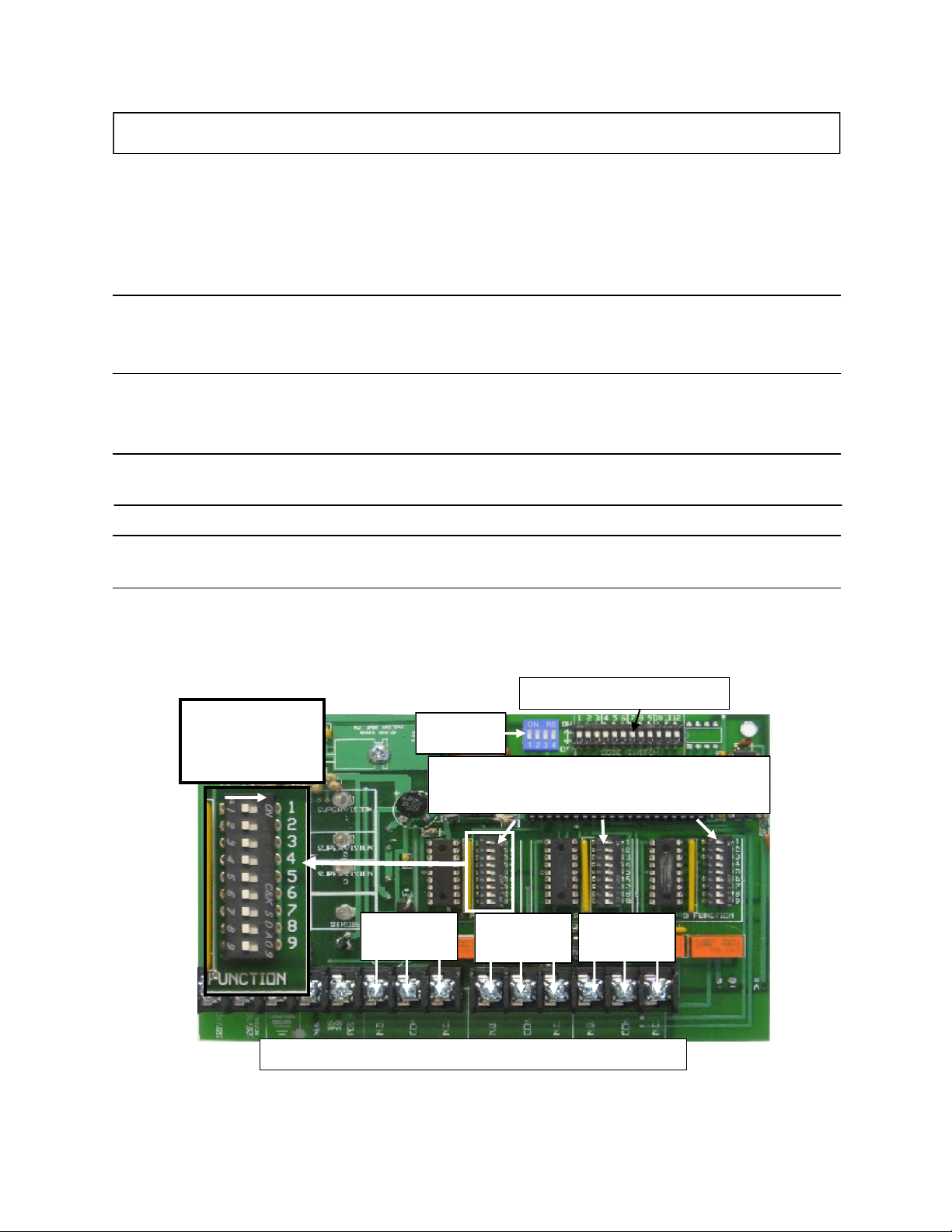
CODE SWITCH SETTINGS
All transmitters and receivers will be shipped from the factory with preprogrammed field codes. This ensures
that your neighbor will not duplicate the same field code as your unit. Your field codes already match, so you do
not need to program any codes. If you ever need to replace a unit due to servicing, the field code can be pro-
grammed to match the existing or new add on units. FOLLOW THE EXAMPLE BELOW…
FOR CODE QUESTIONS? CALL 785-623-1500
89
7
EXAMPLE: CODE 6789
KEY
7
8 9
0
5
63
4
6
OFF ON
Use the # KEY to the left
to make each digit of the
code. It takes three of the
switches to make one num-
ber of the code.
Use switches 1,2,3 for the
first # in the code. Switches
4,5,6 for the second #.
Switches 7,8,9 for the third
#. Switches 10,11,12 for the
fourth #.
Transmitter Code
Switches
INDICATOR LIGHTS
POWER Signals that the Receiver has power and is ready to receive the code from the Transmitter.
STROBE Used for troubleshooting, this light flashes once for each of the four correct digits of the code received. The
light will stay on steady for one second if an incorrect digit of the code is received. Example: If the light
flashes two times and then goes on steady it is indicating that the third digit doesn’t match. If the light flashes
one time and goes on steady it is indicating that the second digit doesn’t match. If the light comes on steady
right away it is indicating that the first digit doesn’t match.
RELAY When this light is on it indicates that its corresponding relay has been activated.
SUPERVISION When this light is flashing it indicates that it has not received its correct code from the
transmitter in the past 3hrs. Sliding function switch #8 to its OFF position will turn off this indicator light.
SUPERVISION FEATURE
The Supervision Feature is a great way for checking at a glance the integrity
of the system. This feature will come on if the receiver has not heard it’s
correct code from the transmitter within the past three hours. The Supervi-
sion Light will begin to blink until the receiver hears it’s correct code again.
If there are two or more receivers on the same transmitter and the Supervi-
sion Light is blinking on both of them, it is indicating that the transmitter is
either turned off or malfunctioning. If only one out of the two receiver’s
Supervision Lights are blinking, it is indicating that that receiver is malfunc-
tioning and that the other receiver and transmitter are good.
OPTIONAL RELAY 2 AND 3
There is also a Supervision Light for each of the relays on the receiver.
These are there for when a receiver is going to use it’s other relays that are
controlled by different transmitters. This will tell you exactly which trans-
mitter is turned off or is not working properly.