4
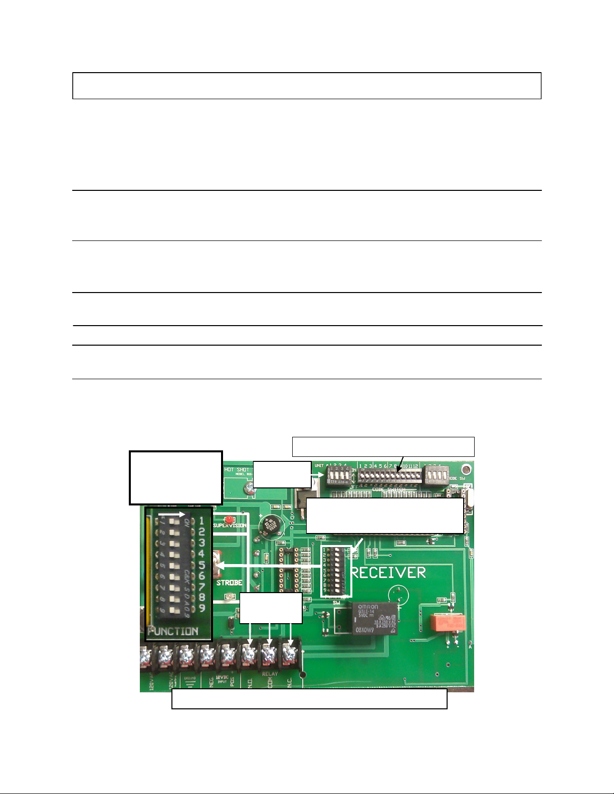
RECEIVER UNIT 810-3R
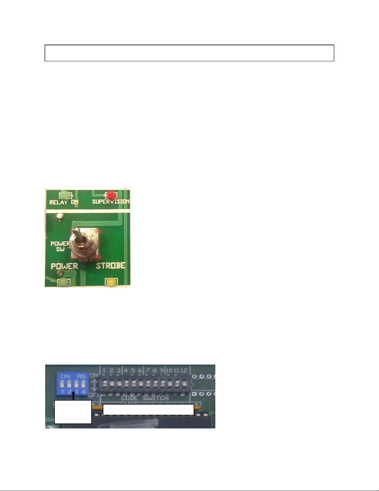
INDICATOR LIGHTS
SUPERVISION FEATURE
The Supervision Feature is a great way for checking at a glance the
integrity of the system. The RED Supervision Light will come on
if the receiver has not heard it’s correct code from the transmitter
within the past three hours. Then the Supervision Light will begin
to blink until the receiver hears it’s correct code again. If there are
two or more receivers on the same transmitter and the Supervision
Light is blinking on both of them, it is indicating that the transmit-
ter is either turned off or malfunctioning. If only one out of the
two receiver’s Supervision Lights are blinking, it is indicating that
that receiver is malfunctioning and that the other receiver and
transmitter are working properly.
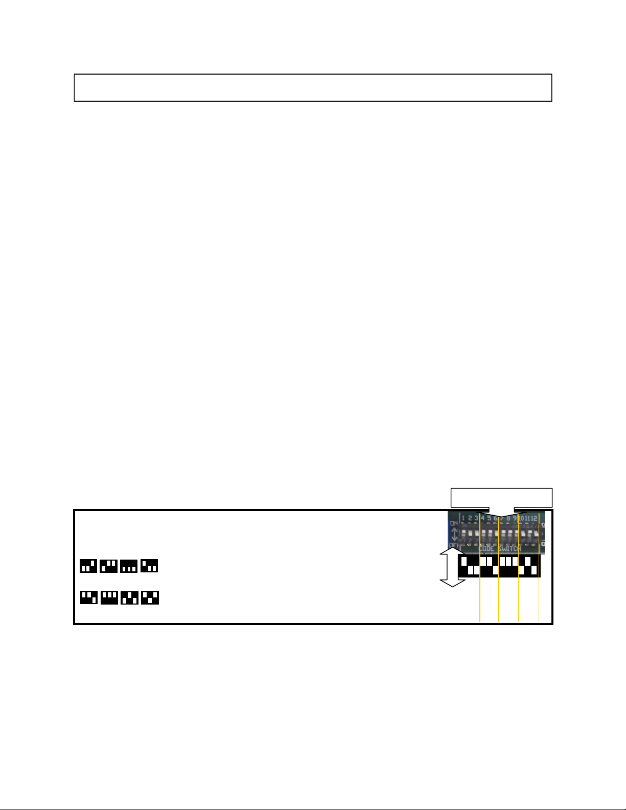
RECEIVER # SWITCHES(1,2,3,4)
When a Hot Shot Receiver (only 810-3R) is going to be used with A Hot Shot 810-3T transmitter using it’s #1,
#2, #3 or #4 SENSOR INPUTS, the receivers going to be used will need to be assigned to the sensor on the
transmitter that will control it. All receivers come factory set in the default mode as a #1 receiver. Meaning they
are only controlled by the SENSOR INPUT #1 of the transmitter. When using the SENSOR INPUT #2, #3 OR
#4 SENSOR INPUT the transmitter you will need to use the FOUR DIP SWITCHES located to the left of the
12-digit code bar on the receiver to program
the receiver so it can be controlled by it’s
designated SENSOR INPUT on the trans-
mitter. You can make it a #2 receiver
(which is controlled by the #2 sensor on the
transmitter) by only turning on the #2 dip-
switch. You can make it a #3 receiver
(which is controlled by the #3 sensor on the
transmitter) by only turning on the #3 dipswitch. This makes it capable for the pivot to control and share multi-
ple wells. Also see Discrete Operation and Multi Pivot Operation in the transmitter section.
Top right of Receiver Board
Receiver #
Switches
POWER Signals that the Receiver has power and is ready to receive the code from the Transmit
ter.
STROBE Used for troubleshooting, this light flashes once for each of the four correct digits of the
code received. The light will stay on steady for one second if an incorrect digit of the
code is received. Example: If the light flashes two times and then goes on steady it is
indicating that the third digit doesn’t match. If the light flashes one time and goes on
steady it is indicating that the second digit doesn’t match. If the light comes on steady
right away it is indicating that the first digit doesn’t match.
RELAY When this light is on it indicates that its corresponding relay has been activated.
SUPERVISION When this light is flashing it indicates that it has not received its correct code
from the transmitter in the past 3hrs. Sliding function switch #8 to its OFF
position will turn off this indicator light.